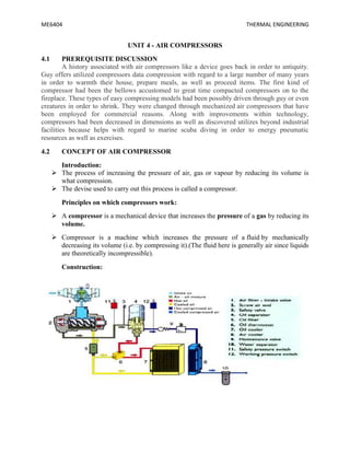
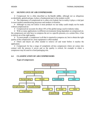
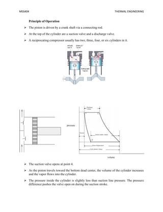
SlideShare a Scribd company logo
ME 6404
THERMAL
ENGINEERING
LECTURE NOTES
UNIT - IV
AIR COMPRESSOR
BIBIN C
ASSISTANT PROFESSOR
DEPARTMENT OF MECHANICAL ENGINEERING
RMK COLLEGE OF ENGINEERING AND TECHNOLOGY
ME6404 THERMAL ENGINEERING
UNIT 4 - AIR COMPRESSORS
4.1 PREREQUISITE DISCUSSION
A history associated with air compressors like a device goes back in order to antiquity.
Guy offers utilized compressors data compression with regard to a large number of many years
in order to warmth their house, prepare meals, as well as proceed items. The first kind of
compressor had been the bellows accustomed to great time compacted compressors on to the
fireplace. These types of easy compressing models had been possibly driven through guy or even
creatures in order to shrink. They were changed through mechanized air compressors that have
been employed for commercial reasons. Along with improvements within technology,
compressors had been decreased in dimensions as well as discovered utilizes beyond industrial
facilities because helps with regard to marine scuba diving in order to energy pneumatic
resources as well as exercises.
4.2 CONCEPT OF AIR COMPRESSOR
Introduction:
 The process of increasing the pressure of air, gas or vapour by reducing its volume is
what compression.
 The devise used to carry out this process is called a compressor.
Principles on which compressors work:
 A compressor is a mechanical device that increases the pressure of a gas by reducing its
volume.
 Compressor is a machine which increases the pressure of a fluid by mechanically
decreasing its volume (i.e. by compressing it).(The fluid here is generally air since liquids
are theoretically incompressible).
Construction:
ME6404 THERMAL ENGINEERING
4.3 SIGNIFICANCE OF AIR COMPRESSORS
 Compressed Air is often described as the fourth utility, although not as ubiquitous
as electricity, petrol and gas, it plays a fundamental part in the modern world.
 The importance of compressed air is often over looked, but in reality it plays a vital part
in most modern manufacturing processes and modern civilization.
 Although we may not realize it most products we use today could simply not be made
without compressed air.
 Compressed air accounts for about 10% of the global energy used in industry today.
 With so many applications in different environments being dependant on compressed air,
the compressors not only have to compress the air to a specific pressure, at a certain flow, it has
to deliver air of the right quality.
 To most people, a compressor is all that is required to compress air, but to obtain the right
quality of the compressed air, more equipment is often needed.
 Filters and dryers are often needed to remove oil and water before it reaches the
application.
 Compressed Air has a range of completely oil-less compressors where air comes into
contact with the process it serves and so the quality is critical, for example in where a
compressor may be used in a food packaging role.
4.4 CLASSIFICATION OF AIR COMPRESSORS
Types of compressors
ME6404 THERMAL ENGINEERING
4.4.1 Positive displacement compressor
 In the positive-displacement type, a given quantity of air or gas is trapped in a
compression chamber and the volume it occupies is mechanically reduced, causing a
corresponding rise in pressure prior to discharge.
 At constant speed, the air flow remains essentially constant with variations in discharge
pressure.
 Ex: Reciprocating compressors, vane compressors & so on.
4.4.2 Dynamic compressors:
 Dynamic compressors impart velocity energy to continuously flowing air or gas by
means of impellers rotating at very high speeds.
 The velocity energy is changed into pressure energy both by the impellers and the
discharge volutes or diffusers.
 In the centrifugal-type dynamic compressors, the shape of the impeller blades determines
the relationship between air flow and the pressure (or head) generate.
 Ex: centrifugal compressors, axial compressors.
4.4.3 Reciprocating compressors
 In a reciprocating compressor, a volume of gas is drawn into a cylinder; it is trapped and
compressed by piston, then discharged into the discharge line.
 The cylinder valves control the flow of gas through the cylinder; these valves act as
check valves.
ME6404 THERMAL ENGINEERING
Principle of Operation
 The piston is driven by a crank shaft via a connecting rod.
 At the top of the cylinder are a suction valve and a discharge valve.
 A reciprocating compressor usually has two, three, four, or six cylinders in it.
 The suction valve opens at point 4.
 As the piston travels toward the bottom dead center, the volume of the cylinder increases
and the vapor flows into the cylinder.
 The pressure inside the cylinder is slightly less than suction line pressure. The pressure
difference pushes the valve open on during the suction stroke.
ME6404 THERMAL ENGINEERING
 At point 2, the pressure inside the cylinder has become slightly greater than discharge
line pressure.
 This causes the valve opening allowing the gas to flow out of the cylinder.
 The volume continues to decrease toward point 3, maintaining a sufficient pressure
difference across the discharge valve to hold it open.
 At point 3, the piston reaches the top dead center and reverses direction.
 At top dead center, as the piston comes to a complete stop prior to reversing direction, the
pressure across the valve is equal.
 So, the discharge valve is closed.
 As the piston moves towards point 4, the volume increases and the pressure decreases in
the cylinder.
 The gas trapped in the cylinder expands as the volume increases until to point 4.
 At point 4, the gas pressure inside the cylinder becomes less than the suction line
pressure, so the suction valve opens again.
 The cycle then starts over again.
 The shape of the re-expansion line (Line 3-4) is dependent on the same compression
exponent that determines the shape of the compression line.
What is the difference between a single and two stage compressor?
 The simplest way to explain the difference between a single stage compressor and dual or
two stage compressor is the number of times that the air is compressed. In a single stage
system the air is compressed once and in a dual stage the air is compressed twice.
 In a single stage piston compressor the air is drawn into a cylinder and compressed in a
single piston stoke to a pressure of approximately 120 PSI. Then it is send to the storage
tank. All rotary compressors are single stage.
 In a dual stage compressor the first step is the same except that the air is not directed to
the storage tank, the air is sent via an inter cooler tube to a second, smaller high pressure
piston and compressed a second time and compressed to a pressure of 175 PSI. Then it is
sent through the after cooler to the storage tank.
 In a dual stage pump the first stage cylinder is always a larger diameter. Also a dual stage
pump will always have an inter cooler tube or finned housing attached to the pump to
cool the air before being compressed a second time.
4.5 ROTARY VANE COMPRESSORS
 Rotary vane compressors consist of a rotor with a number of blades inserted in radial
slots in the rotor.
ME6404 THERMAL ENGINEERING
 The rotor is mounted offset in a larger housing that is either circular or a more complex
shape. As the rotor turns, blades slide in and out of the slots keeping contact with the
outer wall of the housing. Thus, a series of decreasing volumes is created by the rotating
blades.
4.6 MULTISTAGE COMPRESSION:
Multistage compression refers to the compression process completed in more than one
stage i.e., a part of compression occurs in one cylinder and subsequently compressed air is
sent to subsequent cylinders for further compression. In case it is desired to increase the
compression ratio of compressor then multi-stage compression becomes inevitable. If
we look at the expression for volumetric efficiency then it shows that the volumetric
efficiency decreases with increase in pressure ratio. This aspect can also be explained using
p-V representation shown in Figure.
A multi-stage compressor is one in which there are several cylinders of different diameters.
The intake of air in the first stage gets compressed and then it is passed over a cooler to
achieve a temperature very close to ambient air. This cooled air is passed to the intermediate
stage where it is again getting compressed and heated. This air is again passed over a cooler
to achieve a temperature as close to ambient as possible. Then this compressed air is passed
to the final or the third stage of the air compressor where it is compressed to the required
ME6404 THERMAL ENGINEERING
pressure and delivered to the air receiver after cooling sufficiently in an after-cooler.
Advantages of Multi-stage compression:
The work done in compressing the air is reduced, thus power can be
saved
2. Prevents mechanical problems as the air temperature is
controlled
3. The suction and delivery valves remain in cleaner condition as the temperature
and vaporization of lubricating oil is less
4. The machine is smaller and better
balanced
5. Effects from moisture can be handled better, by draining at each
stage
6. Compression approaches near
isothermal
7. Compression ratio at each stage is lower when compared to a single-stage
machine
4.7 WORK DONE IN A SINGLE STAGE RECIPROCATING COMPRESSOR WITH
CLEARANCE VOLUME:
Considering clearance volume: With clearance volume the cycle is represented on Figure. The
work done for compression of air polytropically can be given by the are a enclosed in cycle 1-
2-
3-4. Clearance volume in compressors varies from 1.5% to 35% depending upon type of
compressor.
ME6404 THERMAL ENGINEERING
In the cylinder of reciprocating compressor (V1-V4) shall be the actual volume of air
delivered per cycle. Vd = V1 – V4. This (V1 – V4) is actually the volume of air in hated in
the cycle and delivered subsequently.
If air is considered to behave as perfect gas then pressure, temperature, volume and mass
can be inter related using perfect gas equation. The mass at state 1 may be given as m1 mass
at state 2 shall be m1, but at state 3 after delivery mass reduces to m2 and at state 4 it shall
be m2.
Ideally there shall be no change in temperature during suction and
delivery i.e., T4 = T1 and T2 = T3 from earlier equation
ME6404 THERMAL ENGINEERING
Thus (m1-m2) denotes the mass of air sucked or delivered. For unit mass of air delivered the
work done per kg of air can be given as,
Thus from above expressions it is obvious that the clearance volume reduces the effective
swept volume i.e., the mass of air handled but the work done per kg of air delivered
remains unaffected. From the cycle work estimated as above the theoretical power required for
running compressor shall be,
For single acting compressor running with N rpm, power input required, assuming clearance
volume.
ME6404 THERMAL ENGINEERING
4.8 VOLUMETRIC EFFICIENCY:
Volumetric efficiency of compressor is the measure of the deviation from volume
handling capacity of compressor. Mathematically, the volumetric efficiency is given by the
ratio of actual volume of air sucked and swept volume of cylinder. Ideally the volume of air
sucked should be equal to the swept volume of cylinder, but it is not so in actual case.
Practically the volumetric efficiency lies between 60 to 90%. Volumetric efficiency can be
overall volumetric efficiency and absolute volumetric efficiency as given below.
Here free air condition refers to the standard conditions. Free air condition may be taken
as 1 atm or 1.01325 bar and 15oC or 288K. consideration for free air is necessary as
otherwise the different compressors can not be compared using volumetric efficiency
because specific volume or density of air varies with altitude. It may be seen that a
compressor at datum level (sea level) shall deliver large mass than the same compressor at
high altitude. This concept is used for giving the capacity of compressor in terms of „free air
delivery‟(FAD). “Free air delivery is the volume of air delivered being reduced to free air
conditions”. In case of air the free air delivery can be obtained using perfect gas equation as,
Where subscript a or pa, Va, Ta denote properties at free air
conditions
This volume Va gives „free air delivered‟ per cycle by the compressor. Absolute
volumetric efficiency can be defined, using NTP conditions in place of free air conditions.
ME6404 THERMAL ENGINEERING
Here Vs is the swept volume = V1 – V3 and Vc is the clearance volume =
V3
Volumetric efficiency depends on ambient pressure and temperature, suction pressure and
temperature, ratio of clearance to swept volume, and pressure limits. Volumetric efficiency
increases with decrease in pressure ratio in compressor.
Mathematical analysis of multistage compressor is done with following assumptions:
(i) Compression in all the stages is done following same index of compression and there is no
pressure drop in suction and delivery pressures in each stage. Suction and delivery pressure
remains constant in the stages.
(ii) There is perfect inter cooling between compression
stages.
(iii) Mass handled in different stages is same i.e., mass of air in LP and HP stages are
same. (iv) Air behaves as perfect gas during compression.
From combined p-V diagram the compressor work requirement can be given
as,
ME6404 THERMAL ENGINEERING
4.9 APPLICATION OF COMPRESSORS
 Reciprocating compressors are typically used where high compression ratios (ratio of
discharge to suction pressures) are required per stage without high flow rates, and the
process fluid is relatively dry.
 Screw compressors: Trailer mounted diesel powered units are often seen at construction
sites, and are used to power air operated construction machinery.
 P.E.T bottling industries, gas filling stations usually use reciprocating compressors.
 Processing equipment, Oxygen Generators Oil Atomization use compressors of required
capacity.
 Air compressors: a compressor that takes in air at atmospheric pressure and delivers it at
a higher pressure.
 Compressors serve the basic necessities & form an integral part of the company .
 Pneumatic brakes
 Pneumatic drills
 Pneumatic jacks
 Pneumatic lifts
 Spray painting
 Shop cleaning
 Injecting fuel in Diesel engines
 Refrigeration and Air conditioning systems.
4.10 TECHNICAL TERMS
After cooler - Heat exchangers for cooling air or gas discharged from compressors. They
provide the most effective means of removing moisture from compressed air and gases.
Air-Cooled Compressors - Air-cooled compressors are machines cooled by atmospheric air
circulated around the cylinders or casings.
Base Plate - A metallic structure on which a compressor or other machine is mounted.
Capacity - The capacity of a compressor is the full rated volume of flow of gas compressed and
delivered at conditions of total temperature, total pressure, and composition, prevailing at the
compressor inlet. It sometimes means actual flow rate, rather than rated volume of flow.
Capacity, Actual - Quantity of gas actually compressed and delivered to the discharge system at
rated speed of the machine and under rated pressure conditions. Actual capacity is usually
expressed in cubic feet per minute (cfm) at that stage inlet gas conditions.
ME6404 THERMAL ENGINEERING
Casing - The pressure containing stationary element that encloses the rotor and associated
internal components of a compressor. Includes integral inlet and discharge corrections (nozzles).
Check valve - A check valve is a valve that permits flow in one direction only.
Clearance - The maximum cylinder volume on a working side of the piston minus the piston
displacement volume per stroke. It is usually expressed as a percentage of the displaced volume.
Clearance Pocket - An auxiliary volume that may be opened to the clearance space to increase
the clearance, usually temporarily, to reduce the volumetric efficiency of the air compressor.
Compressibility - A factor expressing the deviation of a gas from the laws of hydraulics.
Compression, Adiabatic - This type of compression is effected when no heat is transferred to or
from the gas during the compression process.
Compression, Isothermal - Isothermal compression is a compression in which the temperature
of the gas remains constant. For perfect gases, it is represented by the equation PV is a constant,
if the process is reversible.
Compression, Polytropic - Compression in which the relationship between the pre-sum and the
volume is expressed by the equation PV is a constant.
Compression Ratio - The ratio of the absolute discharge; press = to the absolute inlet pressure.
Critical Pressure - The limiting value of saturation pressure as the saturation temperature
approaches the critical temperature.
Critical Temperature - The highest temperature at which well defined liquid and vapor states
exist. It is sometimes defined as the highest temperature at which it is possible to liquify a gas by
pressure alone.
Diaphragm - A stationary element between the stages of a multistage centrifugal compressor. It
may include guide vanes for directing the flowing medium to the impeller of the succeeding
stage. In conjunction with an adjacent diaphragm, it forms the diffuser surrounding the impeller.
Diaphragm Routing - A method of removing heat from the flowing medium by circulation of a
coolant in passages built into the diaphragm.
Diffuser - A stationary passage surrounding an impeller, in which velocity pressure imparted to
the flowing medium by the impeller is converted into static pressure.
Displacement - Displacement of a compressor is the piston volume swept out per unit time; it is
usually expressed in cubic feet per minute.
Dynamic Type Compressors - Machines in which air or gas is compressed by the mechanical
action of routing vanes or impellers imparting velocity and pressure to the flowing medium.
Efficiency - Any reference to efficiency of a dynamic type compressor must be accompanied by
a qualifying statement which identifies the efficiency under consideration, as in the following
definitions.
ME6404 THERMAL ENGINEERING
Efficiency, Compression - Ratio of calculated isentropic work requirement to actual
thermodynamic work requirement within the cylinder, the Inner as determined from the cylinder
indicator card.
Efficiency, Isothermal - Ratio of the work calculated on an isothermal basis to the actual work
transferred to the gas during compression.
Efficiency, Mechanical - Ratio of thermodynamic work requirement in the cylinder (a shown by
die indicator card) to actual brake horsepower requirement.
Efficiency, Polytropic - Ratio of the polytropic compression energy transferred to the gas no the
actual energy transferred to the gas.
Efficiency, Volumetric - Ratio of actual capacity to piston displacement, stated as a percentage.
Exhauster - This is a term sometimes applied to a compressor in which the inlet pressure is less
than atmospheric pressure.
Expanders - Turbines or engines in which a gas expands, doing work, and undergoing a drop in
temperature. Use of the term usually implies that the drop in temperature is the principle
objective. The orifice in a refrigeration system also performs this function, but the expander
performs it nearly isentropically, and is thus more effective in cryogenic systems.
Filters - Filters are devices for separating and removing dust and dirt front air before it enters a
compress.
Flange Connection - The flange connection (inlet or discharge) is a means of connecting the
casing to the inlet or discharge piping by means of bolted rims (flanges).
Fluidics - The general subject of instruments and controls dependent upon low rate flow of air or
gas at low pressure as the operating medium. These usually have no moving parts.
Free Air - Air at atmospheric conditions at any specific location. Because the altitude,
barometer, and temperature may vary at different localities and at different times, it follows that
this term does not mean air under identical or standard conditions.
Gas - While from a physical point of view a gas is one of the three basic phases of matter, and
thus air is a gas, a special meaning is assigned in pneumatics practice. The term gas refers to any
gas other than air.
GasBearings - Gas bearings are load carrying machine elements permitting some degree of
motion in which the lubricant is air or some other gas.
Volumetric Efficiency of the Compressor - It is the ratio of actual volume of air drawn in the
compressor to the stroke volume of the compressor.
Mechanical efficiency - It is the ratio of indicated power to shaft power or brake power of
motor.
Isentropic efficiency - It is the ratio of the isentropic power to the brake power required to drive
the compressor.
ME6404 THERMAL ENGINEERING
Centrifugal compressor - The flow of air is perpendicular to the axis of compressor
Axial flow compressor - The flow of air is parallel to the axis of compressor
Compression - The process of increasing the pressure of air, gas and vapour by reducing its
volume is called as compression.
Single acting compressor - The suction , compression and the delivery of air takes on the one
side of piston
Double acting compressor - The suction, compresstion end the delivery of air takes place on
both sides of the piston.
Multi stage compressor - The compression of air from initial pressure to the final pressure is
carried out in more than one cylinder.
Application of compressed air - Pneumatic brakes, drills,jacks,lifts, spray of paintings, shop
cleaning , injecting the fuel in diesel engine, supercharging, refrigeration and in air conditioning
systems.
Inter cooler - It is a simple heat exchanger, exchanges the heat of compressed air from low
pressure compressor to circulating water before the air enters to high pressure compressor. The
purpose of intercooling is to minimize the work of compression.
Isentropic efficiency - It is the ratio of isentropic power to the brake power required to drive the
compressor.
Clearance ratio - It is the ratio of clearance volume to the swept volume or stroke volume is
called as clearance ratio.
Isothermal efficiency - It is the ratio between isothermal work to the actual work of the
compressor.
Compression ratio - The ratio between total volume and the clearance volume of the cylinder
is called compression ratio.
Perfect intercooling - When the temperature of the air leaving the intercooler is equal to the
original atmospheric air temperature, then the inter cooling is called perfect intercooling.
4.11 SOLVED PROBLEMS
1. A single stage double acting air compressor of 150KW power takes air in at 16 bar &
delivers at 6 bar. The compression follows the law PV1.35 = C. the compressor runs at
160rpm with average piston speed of 150 m/min. Determine the size of the cylinder.
Given data
Power (P) = 150KW
ME6404 THERMAL ENGINEERING
Piston speed (2lN) = 150m/min
Speed (N) = 160rpm 160/60 = 2.7rps
Pressure (P1) = 1bar = 100KN/m2
Pressure (P2) = 6bar = 600KN/m2
PV1.35 = C, n = 1.35
Hence it is a polytropic process.
To find
Size of the cylinder (d)?
Solution
It is given that,
2lN = 2.5m/s
l =
l = 0.4629m
since V1 = Vs =
V1 = Vs =
V1 = 0.3635d2
We know that,
Power (P) = 2×W×N (for double acting) For polytropic process, work done
(W) is
W = 82.899
d2
Power (P) =
2×W×N
ME6404 THERMAL ENGINEERING
150 = 2 × 82.899 d2 × 2.7
d2 = 0.3350
d = 0.57M
2. A single stage single acting reciprocating air compressor is required to handle 30m3 of
free air per hour measured at 1bar . the delivery pressure is 6.5 bar and the speed is 450 r.p.m
allowing volumetric efficiency of 75%;an isothermal efficiency of 76% and mechanical
efficiency of 80% Find the indicated mean effective pressure and the power required the
compressor
Given data
Volume V1 =30m2
Pressure P1=1 bar ,
P2=6.5 bar Speed N=450 r.p.m
Volumetric efficiency ηv=75%
Isothermal efficiency ηi=76%
Mechanical efficiency ηm=80%
To find
The indicated mean effective pressure
The power required to drive the compressor
Solution
Indicted Mean Effective Pressure
We know that isothermal work done
= 2.3V1P1
=2.3×105 ×30
=5609×103J/h
And indicated work done=
=7380KJ/h
ME6404 THERMAL ENGINEERING
We know that swept volume of the piston
Vs= =
=40m3/h
Indicated mean effective pressure pm= =
= 184.5kJ/m3
=184.5KN/m2
The power required to drive the compressor
We know that work done by the compressor =
=
=9225KJ/h
Therefore the power required to drive the compressor =
=2.56KW
Result
Indicated mean effective pressure pm=184.5KN/m2
The power required to drive the compressor =2.56KW
3. A two stages, single acting air compressor compresses air to 20bar. The air enters the L.P
cylinder at 1bar and 27oc and leaves it at 4.7bar. The air enters the H.P. cylinder at 4.5bar and
27oc. the size of the L.P cylinder is 400mm diameter and 500mm stroke. The clearance volume
In both cylinder is 4% of the respective stroke volume. The compressor runs at 200rpm, taking
index of compression and expansion in the two cylinders as 1.3, estimate 1. The indicated
power required to run the compressor; and 2. The heat rejected in the intercooler per minute.
ME6404 THERMAL ENGINEERING
Given data
Pressure (P4)= 20bar
Pressure (P1) = 1bar = 1×10⁵ N/m2
Temperature (T1) = 27oC = 27+273 =
300K Pressure (P2) = 4.7bar
Pressure (P3) = 4.5bar
Temperature (T3) = 27oC = 27+273 =
300K Diameter (D1) = 400mm 0.4m
Stroke (L1) = 500mm = 0.5m
N = 200rpm ; n = 1.3
To find
Indicated power required to run the compressor
Solution
We know the swept volume of the L.P cylinder
= 0.06284 m3
And volumetric efficiency,
ηv
= 0.9085 or 90.85%
Volume of air sucked by air pressure compressor,
1.42m3/min
ME6404 THERMAL ENGINEERING
And volume of airsucked by H.P compressor,
We know that indicated worrk done by L.P compressor,
= 2123.3×103 J/min = 2123.3 KJ/min
And indicated workdone by H.P compressor,
= 2043.5×103 J/min = 2034.5 KJ/min
Total indicated work done by the compressor,
W = WL + WH = 2123.3 + 2034.5 = 4157.8 KJ/min
Indicated power required to run the compressor
= 4157.8 / 60
= 69.3KW
ME6404 THERMAL ENGINEERING
4.12 REVIEW QUESTIONS
PART A
1. Draw the P-V diagram of a two stage reciprocating air compressor.
2. What is ton of refrigeration?
3. What is compounding of steam turbine?
4. Name the methods of steam turbine governing.
5. Why is compounding necessary in steam turbine?
6. What is the purpose of using intercooler in multi-stage compression?
7. Indicate the application of reciprocating compressors in industry.
8. What are the advantages of multi stage compression with inter cooling over single stage
compression for the same pressure ratio.
9. Why clearance is necessary and what is its effect on the performance of reciprocating
compressor?
10. Give two merits of rotary compressor over reciprocating compressor.
11. What is meant by single acting compressor?
12. What is meant by double acting compressor?
13. What is meant by single stage compressor?
14. What is meant by multistage compressor?
15. Define isentropic efficiency
16. Define mean effective pressure. How is it related to in power of an I.C engine.
17. What is meant by free air delivered?
18. Explain how flow of air is controlled in a reciprocating compressor?
19. What factors limit the delivery pressure in reciprocating compressor?
20. Name the methods adopted for increasing isothermal efficiency of reciprocating
air compressor.
21. Why clearance is necessary and what is its effect on the performance of
reciprocating compressor?
22. What is compression ratio?
23. What is meant by inter cooler?
PART B
1. Drive an expression for the work done by single stage single acting reciprocating
air compressor.
2. Drive an expression for the volumetric efficiency of reciprocating air compressors
3. Explain the construction and working of a root blower
4. Explain the construction and working of a centrifugal compressor
5. Explain the construction and working of a sliding vane compressor and axial
flow compressor.
6. A single stage single acting air compressor is used to compress air from 1 bar and 22° C
to 6 bar according to the law PV1 .25 = C. The compressor runs at 125 rpm and the ratio
of stroke length to bore of a cylinder is 1.5. If the power required by the
compressor is 20 kW, determine the size of the cylinder.
ME6404 THERMAL ENGINEERING
7. A single stage single acting air compressor is used to compress air from 1.013 bar and
25° C to 7 bar according to law PV 1.3 = C.The bore and stroke of a cylinder are
120mm and 150mm respectively. The compressor runs at 250 rpm .If clearance volume
of the cylinder is 5% of stroke volume and the mechanical efficiency of the compressor
is 85%, determine volumetric efficiency, power, and mass of air delivered per minute.
8. A two stage singe acting air compressor compresses 2m3 airs from 1 bar and 20° C to 15
bar. The air from the low pressure compressor is cooled to 25° C in the intercooler.
Calculate the minimum power required to run the compressor if the compression follows
PV1.25=C and the compressor runs at 400 rpm.

More Related Content

What's hot

ME6016 ADVANCED I.C ENGINES UNIT II
ME6016 ADVANCED I.C ENGINES UNIT IIME6016 ADVANCED I.C ENGINES UNIT II
ME6016 ADVANCED I.C ENGINES UNIT II
BIBIN CHIDAMBARANATHAN
 
Rotary screw air compressor
Rotary screw air compressorRotary screw air compressor
Rotary screw air compressor
Jay Sonar
 
Compressor and Types
Compressor and TypesCompressor and Types
Compressor and Types
Muhammad Usama
 
Centrifugal compressor
Centrifugal compressor Centrifugal compressor
Centrifugal compressor
Héctor Nguema Ondo
 
Air compressor
Air compressorAir compressor
Air compressor
Burhanuddin Kapadia
 
reciprocating compressor
reciprocating compressorreciprocating compressor
reciprocating compressor
Rajesh Sharma
 
Compressor and types of compressors (Thermodynamics)
Compressor and types of compressors (Thermodynamics)Compressor and types of compressors (Thermodynamics)
Compressor and types of compressors (Thermodynamics)
Hasnain Yaseen
 
Compressor final
Compressor finalCompressor final
Compressor final
Er.Nishant Pathak
 
Two Stroke SI and CI Engines
Two Stroke SI and CI EnginesTwo Stroke SI and CI Engines
Two Stroke SI and CI Engines
S.Vijaya Bhaskar
 
CLASSIFICATION OF COMPRESSORS
CLASSIFICATION OF COMPRESSORS CLASSIFICATION OF COMPRESSORS
CLASSIFICATION OF COMPRESSORS
Srinivas Mylapalli
 
Compressor
CompressorCompressor
Compressor
ARUN VISHNU
 
Combustion SI Engines - Unit-III
Combustion SI Engines - Unit-IIICombustion SI Engines - Unit-III
Combustion SI Engines - Unit-III
S.Vijaya Bhaskar
 
Testing and performance of IC engine
Testing and performance of IC engineTesting and performance of IC engine
Testing and performance of IC engine
Mustafa Bzu
 
Se prod thermo_examples_compressor
Se prod thermo_examples_compressorSe prod thermo_examples_compressor
Se prod thermo_examples_compressorVJTI Production
 
Gas turbines
Gas turbinesGas turbines
Gas turbines
Mani Kanth
 
Air compressor
Air compressorAir compressor
Air compressor
Sujeet TAMBE
 
Gas turbine
Gas turbineGas turbine
Gas turbine
naphis ahamad
 
Air Compressors
Air CompressorsAir Compressors
Air Compressors
Keyur Vadodariya
 
Axial Flow Compressor.
Axial Flow Compressor. Axial Flow Compressor.
Axial Flow Compressor.
Urvesh Prajapati
 

What's hot (20)

ME6016 ADVANCED I.C ENGINES UNIT II
ME6016 ADVANCED I.C ENGINES UNIT IIME6016 ADVANCED I.C ENGINES UNIT II
ME6016 ADVANCED I.C ENGINES UNIT II
 
Rotary screw air compressor
Rotary screw air compressorRotary screw air compressor
Rotary screw air compressor
 
Compressor and Types
Compressor and TypesCompressor and Types
Compressor and Types
 
Centrifugal compressor
Centrifugal compressor Centrifugal compressor
Centrifugal compressor
 
Air compressor
Air compressorAir compressor
Air compressor
 
reciprocating compressor
reciprocating compressorreciprocating compressor
reciprocating compressor
 
Compressor and types of compressors (Thermodynamics)
Compressor and types of compressors (Thermodynamics)Compressor and types of compressors (Thermodynamics)
Compressor and types of compressors (Thermodynamics)
 
Compressor final
Compressor finalCompressor final
Compressor final
 
Two Stroke SI and CI Engines
Two Stroke SI and CI EnginesTwo Stroke SI and CI Engines
Two Stroke SI and CI Engines
 
CLASSIFICATION OF COMPRESSORS
CLASSIFICATION OF COMPRESSORS CLASSIFICATION OF COMPRESSORS
CLASSIFICATION OF COMPRESSORS
 
Compressor
CompressorCompressor
Compressor
 
Combustion SI Engines - Unit-III
Combustion SI Engines - Unit-IIICombustion SI Engines - Unit-III
Combustion SI Engines - Unit-III
 
Testing and performance of IC engine
Testing and performance of IC engineTesting and performance of IC engine
Testing and performance of IC engine
 
Se prod thermo_examples_compressor
Se prod thermo_examples_compressorSe prod thermo_examples_compressor
Se prod thermo_examples_compressor
 
Gas turbines
Gas turbinesGas turbines
Gas turbines
 
Air compressor
Air compressorAir compressor
Air compressor
 
Gas turbine
Gas turbineGas turbine
Gas turbine
 
Air Compressors
Air CompressorsAir Compressors
Air Compressors
 
Axial Flow Compressor.
Axial Flow Compressor. Axial Flow Compressor.
Axial Flow Compressor.
 
Compressors
CompressorsCompressors
Compressors
 

Similar to ME 6404 THERMAL ENGINEERING UNIT IV

aditya-151207154017-lva1-app6892 (1).pdf
aditya-151207154017-lva1-app6892 (1).pdfaditya-151207154017-lva1-app6892 (1).pdf
aditya-151207154017-lva1-app6892 (1).pdf
Aqsa181241
 
Reciprocating Compressor
Reciprocating CompressorReciprocating Compressor
Reciprocating Compressor
Aditya Sharma
 
Reciprocating Compressor
Reciprocating CompressorReciprocating Compressor
Reciprocating Compressor
Aditya Sharma
 
chapter-no-3-air-compressors (1).ppt
chapter-no-3-air-compressors (1).pptchapter-no-3-air-compressors (1).ppt
chapter-no-3-air-compressors (1).ppt
ArchanaMaske2
 
5916964.ppt
5916964.ppt5916964.ppt
5916964.ppt
M. Nazir
 
chapter-no-3-air-compressors.ppt
chapter-no-3-air-compressors.pptchapter-no-3-air-compressors.ppt
chapter-no-3-air-compressors.ppt
BeselamuGodebo
 
chapter-no-3-air-compressors.ppt
chapter-no-3-air-compressors.pptchapter-no-3-air-compressors.ppt
chapter-no-3-air-compressors.ppt
zerihunsamuel1
 
chapter-no-3-air-compressors.ppt
chapter-no-3-air-compressors.pptchapter-no-3-air-compressors.ppt
chapter-no-3-air-compressors.ppt
DramilThakkar2
 
chapter-no-3-air-compressors.ppt for electric
chapter-no-3-air-compressors.ppt for electricchapter-no-3-air-compressors.ppt for electric
chapter-no-3-air-compressors.ppt for electric
basant11731
 
compressors types
compressors typescompressors types
compressors types
Engr Farhan Masood
 
Air compressor.pptx
Air compressor.pptxAir compressor.pptx
Air compressor.pptx
Manas Ranjan Roul
 
reciprocating compressor
reciprocating compressorreciprocating compressor
reciprocating compressor
Rajesh Sharma
 
compressors and types
compressors and typescompressors and types
compressors and types
Ali Murtaza
 
Eme (air compressors)
Eme (air compressors)Eme (air compressors)
Eme (air compressors)
Student
 
What Is the Basic Working Principle of an Air Compressor_.pdf
What Is the Basic Working Principle of an Air Compressor_.pdfWhat Is the Basic Working Principle of an Air Compressor_.pdf
What Is the Basic Working Principle of an Air Compressor_.pdf
aliaseo052
 
Basic Component of HVAC(compressor)
Basic Component of HVAC(compressor)Basic Component of HVAC(compressor)
Basic Component of HVAC(compressor)
banukoup
 
What Is the Basic Working Principle of an Air Compressor.docx
What Is the Basic Working Principle of an Air Compressor.docxWhat Is the Basic Working Principle of an Air Compressor.docx
What Is the Basic Working Principle of an Air Compressor.docx
cemenntcompressor
 
chaptrno-140114211033-phpapp02.pptx
chaptrno-140114211033-phpapp02.pptxchaptrno-140114211033-phpapp02.pptx
chaptrno-140114211033-phpapp02.pptx
prabhakarjha82
 
Centrifugal compressor in IFFCO
Centrifugal compressor   in IFFCOCentrifugal compressor   in IFFCO
Centrifugal compressor in IFFCO
Anand Patel
 

Similar to ME 6404 THERMAL ENGINEERING UNIT IV (20)

Compressor
CompressorCompressor
Compressor
 
aditya-151207154017-lva1-app6892 (1).pdf
aditya-151207154017-lva1-app6892 (1).pdfaditya-151207154017-lva1-app6892 (1).pdf
aditya-151207154017-lva1-app6892 (1).pdf
 
Reciprocating Compressor
Reciprocating CompressorReciprocating Compressor
Reciprocating Compressor
 
Reciprocating Compressor
Reciprocating CompressorReciprocating Compressor
Reciprocating Compressor
 
chapter-no-3-air-compressors (1).ppt
chapter-no-3-air-compressors (1).pptchapter-no-3-air-compressors (1).ppt
chapter-no-3-air-compressors (1).ppt
 
5916964.ppt
5916964.ppt5916964.ppt
5916964.ppt
 
chapter-no-3-air-compressors.ppt
chapter-no-3-air-compressors.pptchapter-no-3-air-compressors.ppt
chapter-no-3-air-compressors.ppt
 
chapter-no-3-air-compressors.ppt
chapter-no-3-air-compressors.pptchapter-no-3-air-compressors.ppt
chapter-no-3-air-compressors.ppt
 
chapter-no-3-air-compressors.ppt
chapter-no-3-air-compressors.pptchapter-no-3-air-compressors.ppt
chapter-no-3-air-compressors.ppt
 
chapter-no-3-air-compressors.ppt for electric
chapter-no-3-air-compressors.ppt for electricchapter-no-3-air-compressors.ppt for electric
chapter-no-3-air-compressors.ppt for electric
 
compressors types
compressors typescompressors types
compressors types
 
Air compressor.pptx
Air compressor.pptxAir compressor.pptx
Air compressor.pptx
 
reciprocating compressor
reciprocating compressorreciprocating compressor
reciprocating compressor
 
compressors and types
compressors and typescompressors and types
compressors and types
 
Eme (air compressors)
Eme (air compressors)Eme (air compressors)
Eme (air compressors)
 
What Is the Basic Working Principle of an Air Compressor_.pdf
What Is the Basic Working Principle of an Air Compressor_.pdfWhat Is the Basic Working Principle of an Air Compressor_.pdf
What Is the Basic Working Principle of an Air Compressor_.pdf
 
Basic Component of HVAC(compressor)
Basic Component of HVAC(compressor)Basic Component of HVAC(compressor)
Basic Component of HVAC(compressor)
 
What Is the Basic Working Principle of an Air Compressor.docx
What Is the Basic Working Principle of an Air Compressor.docxWhat Is the Basic Working Principle of an Air Compressor.docx
What Is the Basic Working Principle of an Air Compressor.docx
 
chaptrno-140114211033-phpapp02.pptx
chaptrno-140114211033-phpapp02.pptxchaptrno-140114211033-phpapp02.pptx
chaptrno-140114211033-phpapp02.pptx
 
Centrifugal compressor in IFFCO
Centrifugal compressor   in IFFCOCentrifugal compressor   in IFFCO
Centrifugal compressor in IFFCO
 

More from BIBIN CHIDAMBARANATHAN

ME8391 ENGINEERING THERMODYNAMICS UNIT II (SCANNED).pdf
ME8391 ENGINEERING THERMODYNAMICS UNIT II (SCANNED).pdfME8391 ENGINEERING THERMODYNAMICS UNIT II (SCANNED).pdf
ME8391 ENGINEERING THERMODYNAMICS UNIT II (SCANNED).pdf
BIBIN CHIDAMBARANATHAN
 
ME8391 ENGINEERING THERMODYNAMICS UNIT V (SCANNED).pdf
ME8391 ENGINEERING THERMODYNAMICS UNIT V (SCANNED).pdfME8391 ENGINEERING THERMODYNAMICS UNIT V (SCANNED).pdf
ME8391 ENGINEERING THERMODYNAMICS UNIT V (SCANNED).pdf
BIBIN CHIDAMBARANATHAN
 
ME8391 ENGINEERING THERMODYNAMICS UNIT III (SCANNED).pdf
ME8391 ENGINEERING THERMODYNAMICS UNIT III (SCANNED).pdfME8391 ENGINEERING THERMODYNAMICS UNIT III (SCANNED).pdf
ME8391 ENGINEERING THERMODYNAMICS UNIT III (SCANNED).pdf
BIBIN CHIDAMBARANATHAN
 
ME8391 ENGINEERING THERMODYNAMICS UNIT IV (SCANNED).pdf
ME8391 ENGINEERING THERMODYNAMICS UNIT IV (SCANNED).pdfME8391 ENGINEERING THERMODYNAMICS UNIT IV (SCANNED).pdf
ME8391 ENGINEERING THERMODYNAMICS UNIT IV (SCANNED).pdf
BIBIN CHIDAMBARANATHAN
 
ME8391 ENGINEERING THERMODYNAMICS UNIT I (SCANNED).pdf
ME8391 ENGINEERING THERMODYNAMICS UNIT I (SCANNED).pdfME8391 ENGINEERING THERMODYNAMICS UNIT I (SCANNED).pdf
ME8391 ENGINEERING THERMODYNAMICS UNIT I (SCANNED).pdf
BIBIN CHIDAMBARANATHAN
 
THERMODYNAMICS NOTES - HAND WRITTEN - unit - 1 - PART 1.pdf
THERMODYNAMICS NOTES - HAND WRITTEN - unit - 1 - PART 1.pdfTHERMODYNAMICS NOTES - HAND WRITTEN - unit - 1 - PART 1.pdf
THERMODYNAMICS NOTES - HAND WRITTEN - unit - 1 - PART 1.pdf
BIBIN CHIDAMBARANATHAN
 
THERMODYNAMICS NOTES - HAND WRITTEN - unit - 1 - PART 2.pdf
THERMODYNAMICS NOTES - HAND WRITTEN - unit - 1 - PART 2.pdfTHERMODYNAMICS NOTES - HAND WRITTEN - unit - 1 - PART 2.pdf
THERMODYNAMICS NOTES - HAND WRITTEN - unit - 1 - PART 2.pdf
BIBIN CHIDAMBARANATHAN
 
X10885 (omf751)
X10885 (omf751)X10885 (omf751)
X10885 (omf751)
BIBIN CHIDAMBARANATHAN
 
X10884 (omf551)
X10884 (omf551)X10884 (omf551)
X10884 (omf551)
BIBIN CHIDAMBARANATHAN
 
X10732 (mg8591)
X10732 (mg8591)X10732 (mg8591)
X10732 (mg8591)
BIBIN CHIDAMBARANATHAN
 
X10730 (mg8091)
X10730 (mg8091)X10730 (mg8091)
X10730 (mg8091)
BIBIN CHIDAMBARANATHAN
 
X10730 (mg8091)
X10730 (mg8091)X10730 (mg8091)
X10730 (mg8091)
BIBIN CHIDAMBARANATHAN
 
X10713 (me8793)
X10713 (me8793)X10713 (me8793)
X10713 (me8793)
BIBIN CHIDAMBARANATHAN
 
X10712 (me8792)
X10712 (me8792)X10712 (me8792)
X10712 (me8792)
BIBIN CHIDAMBARANATHAN
 
X10711 (me8791)
X10711 (me8791)X10711 (me8791)
X10711 (me8791)
BIBIN CHIDAMBARANATHAN
 
X10710 (me8694)
X10710 (me8694)X10710 (me8694)
X10710 (me8694)
BIBIN CHIDAMBARANATHAN
 
X10709 (me8693)
X10709 (me8693)X10709 (me8693)
X10709 (me8693)
BIBIN CHIDAMBARANATHAN
 
X10708 (me8692)
X10708 (me8692)X10708 (me8692)
X10708 (me8692)
BIBIN CHIDAMBARANATHAN
 
X10707 (me8691)
X10707 (me8691)X10707 (me8691)
X10707 (me8691)
BIBIN CHIDAMBARANATHAN
 
X10706 (me8651)
X10706 (me8651)X10706 (me8651)
X10706 (me8651)
BIBIN CHIDAMBARANATHAN
 

More from BIBIN CHIDAMBARANATHAN (20)

ME8391 ENGINEERING THERMODYNAMICS UNIT II (SCANNED).pdf
ME8391 ENGINEERING THERMODYNAMICS UNIT II (SCANNED).pdfME8391 ENGINEERING THERMODYNAMICS UNIT II (SCANNED).pdf
ME8391 ENGINEERING THERMODYNAMICS UNIT II (SCANNED).pdf
 
ME8391 ENGINEERING THERMODYNAMICS UNIT V (SCANNED).pdf
ME8391 ENGINEERING THERMODYNAMICS UNIT V (SCANNED).pdfME8391 ENGINEERING THERMODYNAMICS UNIT V (SCANNED).pdf
ME8391 ENGINEERING THERMODYNAMICS UNIT V (SCANNED).pdf
 
ME8391 ENGINEERING THERMODYNAMICS UNIT III (SCANNED).pdf
ME8391 ENGINEERING THERMODYNAMICS UNIT III (SCANNED).pdfME8391 ENGINEERING THERMODYNAMICS UNIT III (SCANNED).pdf
ME8391 ENGINEERING THERMODYNAMICS UNIT III (SCANNED).pdf
 
ME8391 ENGINEERING THERMODYNAMICS UNIT IV (SCANNED).pdf
ME8391 ENGINEERING THERMODYNAMICS UNIT IV (SCANNED).pdfME8391 ENGINEERING THERMODYNAMICS UNIT IV (SCANNED).pdf
ME8391 ENGINEERING THERMODYNAMICS UNIT IV (SCANNED).pdf
 
ME8391 ENGINEERING THERMODYNAMICS UNIT I (SCANNED).pdf
ME8391 ENGINEERING THERMODYNAMICS UNIT I (SCANNED).pdfME8391 ENGINEERING THERMODYNAMICS UNIT I (SCANNED).pdf
ME8391 ENGINEERING THERMODYNAMICS UNIT I (SCANNED).pdf
 
THERMODYNAMICS NOTES - HAND WRITTEN - unit - 1 - PART 1.pdf
THERMODYNAMICS NOTES - HAND WRITTEN - unit - 1 - PART 1.pdfTHERMODYNAMICS NOTES - HAND WRITTEN - unit - 1 - PART 1.pdf
THERMODYNAMICS NOTES - HAND WRITTEN - unit - 1 - PART 1.pdf
 
THERMODYNAMICS NOTES - HAND WRITTEN - unit - 1 - PART 2.pdf
THERMODYNAMICS NOTES - HAND WRITTEN - unit - 1 - PART 2.pdfTHERMODYNAMICS NOTES - HAND WRITTEN - unit - 1 - PART 2.pdf
THERMODYNAMICS NOTES - HAND WRITTEN - unit - 1 - PART 2.pdf
 
X10885 (omf751)
X10885 (omf751)X10885 (omf751)
X10885 (omf751)
 
X10884 (omf551)
X10884 (omf551)X10884 (omf551)
X10884 (omf551)
 
X10732 (mg8591)
X10732 (mg8591)X10732 (mg8591)
X10732 (mg8591)
 
X10730 (mg8091)
X10730 (mg8091)X10730 (mg8091)
X10730 (mg8091)
 
X10730 (mg8091)
X10730 (mg8091)X10730 (mg8091)
X10730 (mg8091)
 
X10713 (me8793)
X10713 (me8793)X10713 (me8793)
X10713 (me8793)
 
X10712 (me8792)
X10712 (me8792)X10712 (me8792)
X10712 (me8792)
 
X10711 (me8791)
X10711 (me8791)X10711 (me8791)
X10711 (me8791)
 
X10710 (me8694)
X10710 (me8694)X10710 (me8694)
X10710 (me8694)
 
X10709 (me8693)
X10709 (me8693)X10709 (me8693)
X10709 (me8693)
 
X10708 (me8692)
X10708 (me8692)X10708 (me8692)
X10708 (me8692)
 
X10707 (me8691)
X10707 (me8691)X10707 (me8691)
X10707 (me8691)
 
X10706 (me8651)
X10706 (me8651)X10706 (me8651)
X10706 (me8651)
 

Recently uploaded

Cosmetic shop management system project report.pdf
Cosmetic shop management system project report.pdfCosmetic shop management system project report.pdf
Cosmetic shop management system project report.pdf
Kamal Acharya
 
AKS UNIVERSITY Satna Final Year Project By OM Hardaha.pdf
AKS UNIVERSITY Satna Final Year Project By OM Hardaha.pdfAKS UNIVERSITY Satna Final Year Project By OM Hardaha.pdf
AKS UNIVERSITY Satna Final Year Project By OM Hardaha.pdf
SamSarthak3
 
addressing modes in computer architecture
addressing modes  in computer architectureaddressing modes  in computer architecture
addressing modes in computer architecture
ShahidSultan24
 
DESIGN A COTTON SEED SEPARATION MACHINE.docx
DESIGN A COTTON SEED SEPARATION MACHINE.docxDESIGN A COTTON SEED SEPARATION MACHINE.docx
DESIGN A COTTON SEED SEPARATION MACHINE.docx
FluxPrime1
 
HYDROPOWER - Hydroelectric power generation
HYDROPOWER - Hydroelectric power generationHYDROPOWER - Hydroelectric power generation
HYDROPOWER - Hydroelectric power generation
Robbie Edward Sayers
 
Forklift Classes Overview by Intella Parts
Forklift Classes Overview by Intella PartsForklift Classes Overview by Intella Parts
Forklift Classes Overview by Intella Parts
Intella Parts
 
TECHNICAL TRAINING MANUAL GENERAL FAMILIARIZATION COURSE
TECHNICAL TRAINING MANUAL   GENERAL FAMILIARIZATION COURSETECHNICAL TRAINING MANUAL   GENERAL FAMILIARIZATION COURSE
TECHNICAL TRAINING MANUAL GENERAL FAMILIARIZATION COURSE
DuvanRamosGarzon1
 
Top 10 Oil and Gas Projects in Saudi Arabia 2024.pdf
Top 10 Oil and Gas Projects in Saudi Arabia 2024.pdfTop 10 Oil and Gas Projects in Saudi Arabia 2024.pdf
Top 10 Oil and Gas Projects in Saudi Arabia 2024.pdf
Teleport Manpower Consultant
 
NO1 Uk best vashikaran specialist in delhi vashikaran baba near me online vas...
NO1 Uk best vashikaran specialist in delhi vashikaran baba near me online vas...NO1 Uk best vashikaran specialist in delhi vashikaran baba near me online vas...
NO1 Uk best vashikaran specialist in delhi vashikaran baba near me online vas...
Amil Baba Dawood bangali
 
Vaccine management system project report documentation..pdf
Vaccine management system project report documentation..pdfVaccine management system project report documentation..pdf
Vaccine management system project report documentation..pdf
Kamal Acharya
 
Quality defects in TMT Bars, Possible causes and Potential Solutions.
Quality defects in TMT Bars, Possible causes and Potential Solutions.Quality defects in TMT Bars, Possible causes and Potential Solutions.
Quality defects in TMT Bars, Possible causes and Potential Solutions.
PrashantGoswami42
 
Hybrid optimization of pumped hydro system and solar- Engr. Abdul-Azeez.pdf
Hybrid optimization of pumped hydro system and solar- Engr. Abdul-Azeez.pdfHybrid optimization of pumped hydro system and solar- Engr. Abdul-Azeez.pdf
Hybrid optimization of pumped hydro system and solar- Engr. Abdul-Azeez.pdf
fxintegritypublishin
 
LIGA(E)11111111111111111111111111111111111111111.ppt
LIGA(E)11111111111111111111111111111111111111111.pptLIGA(E)11111111111111111111111111111111111111111.ppt
LIGA(E)11111111111111111111111111111111111111111.ppt
ssuser9bd3ba
 
CFD Simulation of By-pass Flow in a HRSG module by R&R Consult.pptx
CFD Simulation of By-pass Flow in a HRSG module by R&R Consult.pptxCFD Simulation of By-pass Flow in a HRSG module by R&R Consult.pptx
CFD Simulation of By-pass Flow in a HRSG module by R&R Consult.pptx
R&R Consult
 
ethical hacking in wireless-hacking1.ppt
ethical hacking in wireless-hacking1.pptethical hacking in wireless-hacking1.ppt
ethical hacking in wireless-hacking1.ppt
Jayaprasanna4
 
J.Yang, ICLR 2024, MLILAB, KAIST AI.pdf
J.Yang,  ICLR 2024, MLILAB, KAIST AI.pdfJ.Yang,  ICLR 2024, MLILAB, KAIST AI.pdf
J.Yang, ICLR 2024, MLILAB, KAIST AI.pdf
MLILAB
 
Sachpazis:Terzaghi Bearing Capacity Estimation in simple terms with Calculati...
Sachpazis:Terzaghi Bearing Capacity Estimation in simple terms with Calculati...Sachpazis:Terzaghi Bearing Capacity Estimation in simple terms with Calculati...
Sachpazis:Terzaghi Bearing Capacity Estimation in simple terms with Calculati...
Dr.Costas Sachpazis
 
WATER CRISIS and its solutions-pptx 1234
WATER CRISIS and its solutions-pptx 1234WATER CRISIS and its solutions-pptx 1234
WATER CRISIS and its solutions-pptx 1234
AafreenAbuthahir2
 
Nuclear Power Economics and Structuring 2024
Nuclear Power Economics and Structuring 2024Nuclear Power Economics and Structuring 2024
Nuclear Power Economics and Structuring 2024
Massimo Talia
 
Immunizing Image Classifiers Against Localized Adversary Attacks
Immunizing Image Classifiers Against Localized Adversary AttacksImmunizing Image Classifiers Against Localized Adversary Attacks
Immunizing Image Classifiers Against Localized Adversary Attacks
gerogepatton
 

Recently uploaded (20)

Cosmetic shop management system project report.pdf
Cosmetic shop management system project report.pdfCosmetic shop management system project report.pdf
Cosmetic shop management system project report.pdf
 
AKS UNIVERSITY Satna Final Year Project By OM Hardaha.pdf
AKS UNIVERSITY Satna Final Year Project By OM Hardaha.pdfAKS UNIVERSITY Satna Final Year Project By OM Hardaha.pdf
AKS UNIVERSITY Satna Final Year Project By OM Hardaha.pdf
 
addressing modes in computer architecture
addressing modes  in computer architectureaddressing modes  in computer architecture
addressing modes in computer architecture
 
DESIGN A COTTON SEED SEPARATION MACHINE.docx
DESIGN A COTTON SEED SEPARATION MACHINE.docxDESIGN A COTTON SEED SEPARATION MACHINE.docx
DESIGN A COTTON SEED SEPARATION MACHINE.docx
 
HYDROPOWER - Hydroelectric power generation
HYDROPOWER - Hydroelectric power generationHYDROPOWER - Hydroelectric power generation
HYDROPOWER - Hydroelectric power generation
 
Forklift Classes Overview by Intella Parts
Forklift Classes Overview by Intella PartsForklift Classes Overview by Intella Parts
Forklift Classes Overview by Intella Parts
 
TECHNICAL TRAINING MANUAL GENERAL FAMILIARIZATION COURSE
TECHNICAL TRAINING MANUAL   GENERAL FAMILIARIZATION COURSETECHNICAL TRAINING MANUAL   GENERAL FAMILIARIZATION COURSE
TECHNICAL TRAINING MANUAL GENERAL FAMILIARIZATION COURSE
 
Top 10 Oil and Gas Projects in Saudi Arabia 2024.pdf
Top 10 Oil and Gas Projects in Saudi Arabia 2024.pdfTop 10 Oil and Gas Projects in Saudi Arabia 2024.pdf
Top 10 Oil and Gas Projects in Saudi Arabia 2024.pdf
 
NO1 Uk best vashikaran specialist in delhi vashikaran baba near me online vas...
NO1 Uk best vashikaran specialist in delhi vashikaran baba near me online vas...NO1 Uk best vashikaran specialist in delhi vashikaran baba near me online vas...
NO1 Uk best vashikaran specialist in delhi vashikaran baba near me online vas...
 
Vaccine management system project report documentation..pdf
Vaccine management system project report documentation..pdfVaccine management system project report documentation..pdf
Vaccine management system project report documentation..pdf
 
Quality defects in TMT Bars, Possible causes and Potential Solutions.
Quality defects in TMT Bars, Possible causes and Potential Solutions.Quality defects in TMT Bars, Possible causes and Potential Solutions.
Quality defects in TMT Bars, Possible causes and Potential Solutions.
 
Hybrid optimization of pumped hydro system and solar- Engr. Abdul-Azeez.pdf
Hybrid optimization of pumped hydro system and solar- Engr. Abdul-Azeez.pdfHybrid optimization of pumped hydro system and solar- Engr. Abdul-Azeez.pdf
Hybrid optimization of pumped hydro system and solar- Engr. Abdul-Azeez.pdf
 
LIGA(E)11111111111111111111111111111111111111111.ppt
LIGA(E)11111111111111111111111111111111111111111.pptLIGA(E)11111111111111111111111111111111111111111.ppt
LIGA(E)11111111111111111111111111111111111111111.ppt
 
CFD Simulation of By-pass Flow in a HRSG module by R&R Consult.pptx
CFD Simulation of By-pass Flow in a HRSG module by R&R Consult.pptxCFD Simulation of By-pass Flow in a HRSG module by R&R Consult.pptx
CFD Simulation of By-pass Flow in a HRSG module by R&R Consult.pptx
 
ethical hacking in wireless-hacking1.ppt
ethical hacking in wireless-hacking1.pptethical hacking in wireless-hacking1.ppt
ethical hacking in wireless-hacking1.ppt
 
J.Yang, ICLR 2024, MLILAB, KAIST AI.pdf
J.Yang,  ICLR 2024, MLILAB, KAIST AI.pdfJ.Yang,  ICLR 2024, MLILAB, KAIST AI.pdf
J.Yang, ICLR 2024, MLILAB, KAIST AI.pdf
 
Sachpazis:Terzaghi Bearing Capacity Estimation in simple terms with Calculati...
Sachpazis:Terzaghi Bearing Capacity Estimation in simple terms with Calculati...Sachpazis:Terzaghi Bearing Capacity Estimation in simple terms with Calculati...
Sachpazis:Terzaghi Bearing Capacity Estimation in simple terms with Calculati...
 
WATER CRISIS and its solutions-pptx 1234
WATER CRISIS and its solutions-pptx 1234WATER CRISIS and its solutions-pptx 1234
WATER CRISIS and its solutions-pptx 1234
 
Nuclear Power Economics and Structuring 2024
Nuclear Power Economics and Structuring 2024Nuclear Power Economics and Structuring 2024
Nuclear Power Economics and Structuring 2024
 
Immunizing Image Classifiers Against Localized Adversary Attacks
Immunizing Image Classifiers Against Localized Adversary AttacksImmunizing Image Classifiers Against Localized Adversary Attacks
Immunizing Image Classifiers Against Localized Adversary Attacks
 

ME 6404 THERMAL ENGINEERING UNIT IV

  • 1. ME 6404 THERMAL ENGINEERING LECTURE NOTES UNIT - IV AIR COMPRESSOR BIBIN C ASSISTANT PROFESSOR DEPARTMENT OF MECHANICAL ENGINEERING RMK COLLEGE OF ENGINEERING AND TECHNOLOGY
  • 2. ME6404 THERMAL ENGINEERING UNIT 4 - AIR COMPRESSORS 4.1 PREREQUISITE DISCUSSION A history associated with air compressors like a device goes back in order to antiquity. Guy offers utilized compressors data compression with regard to a large number of many years in order to warmth their house, prepare meals, as well as proceed items. The first kind of compressor had been the bellows accustomed to great time compacted compressors on to the fireplace. These types of easy compressing models had been possibly driven through guy or even creatures in order to shrink. They were changed through mechanized air compressors that have been employed for commercial reasons. Along with improvements within technology, compressors had been decreased in dimensions as well as discovered utilizes beyond industrial facilities because helps with regard to marine scuba diving in order to energy pneumatic resources as well as exercises. 4.2 CONCEPT OF AIR COMPRESSOR Introduction:  The process of increasing the pressure of air, gas or vapour by reducing its volume is what compression.  The devise used to carry out this process is called a compressor. Principles on which compressors work:  A compressor is a mechanical device that increases the pressure of a gas by reducing its volume.  Compressor is a machine which increases the pressure of a fluid by mechanically decreasing its volume (i.e. by compressing it).(The fluid here is generally air since liquids are theoretically incompressible). Construction:
  • 3. ME6404 THERMAL ENGINEERING 4.3 SIGNIFICANCE OF AIR COMPRESSORS  Compressed Air is often described as the fourth utility, although not as ubiquitous as electricity, petrol and gas, it plays a fundamental part in the modern world.  The importance of compressed air is often over looked, but in reality it plays a vital part in most modern manufacturing processes and modern civilization.  Although we may not realize it most products we use today could simply not be made without compressed air.  Compressed air accounts for about 10% of the global energy used in industry today.  With so many applications in different environments being dependant on compressed air, the compressors not only have to compress the air to a specific pressure, at a certain flow, it has to deliver air of the right quality.  To most people, a compressor is all that is required to compress air, but to obtain the right quality of the compressed air, more equipment is often needed.  Filters and dryers are often needed to remove oil and water before it reaches the application.  Compressed Air has a range of completely oil-less compressors where air comes into contact with the process it serves and so the quality is critical, for example in where a compressor may be used in a food packaging role. 4.4 CLASSIFICATION OF AIR COMPRESSORS Types of compressors
  • 4. ME6404 THERMAL ENGINEERING 4.4.1 Positive displacement compressor  In the positive-displacement type, a given quantity of air or gas is trapped in a compression chamber and the volume it occupies is mechanically reduced, causing a corresponding rise in pressure prior to discharge.  At constant speed, the air flow remains essentially constant with variations in discharge pressure.  Ex: Reciprocating compressors, vane compressors & so on. 4.4.2 Dynamic compressors:  Dynamic compressors impart velocity energy to continuously flowing air or gas by means of impellers rotating at very high speeds.  The velocity energy is changed into pressure energy both by the impellers and the discharge volutes or diffusers.  In the centrifugal-type dynamic compressors, the shape of the impeller blades determines the relationship between air flow and the pressure (or head) generate.  Ex: centrifugal compressors, axial compressors. 4.4.3 Reciprocating compressors  In a reciprocating compressor, a volume of gas is drawn into a cylinder; it is trapped and compressed by piston, then discharged into the discharge line.  The cylinder valves control the flow of gas through the cylinder; these valves act as check valves.
  • 5. ME6404 THERMAL ENGINEERING Principle of Operation  The piston is driven by a crank shaft via a connecting rod.  At the top of the cylinder are a suction valve and a discharge valve.  A reciprocating compressor usually has two, three, four, or six cylinders in it.  The suction valve opens at point 4.  As the piston travels toward the bottom dead center, the volume of the cylinder increases and the vapor flows into the cylinder.  The pressure inside the cylinder is slightly less than suction line pressure. The pressure difference pushes the valve open on during the suction stroke. ME6404 THERMAL ENGINEERING Principle of Operation  The piston is driven by a crank shaft via a connecting rod.  At the top of the cylinder are a suction valve and a discharge valve.  A reciprocating compressor usually has two, three, four, or six cylinders in it.  The suction valve opens at point 4.  As the piston travels toward the bottom dead center, the volume of the cylinder increases and the vapor flows into the cylinder.  The pressure inside the cylinder is slightly less than suction line pressure. The pressure difference pushes the valve open on during the suction stroke. ME6404 THERMAL ENGINEERING Principle of Operation  The piston is driven by a crank shaft via a connecting rod.  At the top of the cylinder are a suction valve and a discharge valve.  A reciprocating compressor usually has two, three, four, or six cylinders in it.  The suction valve opens at point 4.  As the piston travels toward the bottom dead center, the volume of the cylinder increases and the vapor flows into the cylinder.  The pressure inside the cylinder is slightly less than suction line pressure. The pressure difference pushes the valve open on during the suction stroke.
  • 6. ME6404 THERMAL ENGINEERING  At point 2, the pressure inside the cylinder has become slightly greater than discharge line pressure.  This causes the valve opening allowing the gas to flow out of the cylinder.  The volume continues to decrease toward point 3, maintaining a sufficient pressure difference across the discharge valve to hold it open.  At point 3, the piston reaches the top dead center and reverses direction.  At top dead center, as the piston comes to a complete stop prior to reversing direction, the pressure across the valve is equal.  So, the discharge valve is closed.  As the piston moves towards point 4, the volume increases and the pressure decreases in the cylinder.  The gas trapped in the cylinder expands as the volume increases until to point 4.  At point 4, the gas pressure inside the cylinder becomes less than the suction line pressure, so the suction valve opens again.  The cycle then starts over again.  The shape of the re-expansion line (Line 3-4) is dependent on the same compression exponent that determines the shape of the compression line. What is the difference between a single and two stage compressor?  The simplest way to explain the difference between a single stage compressor and dual or two stage compressor is the number of times that the air is compressed. In a single stage system the air is compressed once and in a dual stage the air is compressed twice.  In a single stage piston compressor the air is drawn into a cylinder and compressed in a single piston stoke to a pressure of approximately 120 PSI. Then it is send to the storage tank. All rotary compressors are single stage.  In a dual stage compressor the first step is the same except that the air is not directed to the storage tank, the air is sent via an inter cooler tube to a second, smaller high pressure piston and compressed a second time and compressed to a pressure of 175 PSI. Then it is sent through the after cooler to the storage tank.  In a dual stage pump the first stage cylinder is always a larger diameter. Also a dual stage pump will always have an inter cooler tube or finned housing attached to the pump to cool the air before being compressed a second time. 4.5 ROTARY VANE COMPRESSORS  Rotary vane compressors consist of a rotor with a number of blades inserted in radial slots in the rotor.
  • 7. ME6404 THERMAL ENGINEERING  The rotor is mounted offset in a larger housing that is either circular or a more complex shape. As the rotor turns, blades slide in and out of the slots keeping contact with the outer wall of the housing. Thus, a series of decreasing volumes is created by the rotating blades. 4.6 MULTISTAGE COMPRESSION: Multistage compression refers to the compression process completed in more than one stage i.e., a part of compression occurs in one cylinder and subsequently compressed air is sent to subsequent cylinders for further compression. In case it is desired to increase the compression ratio of compressor then multi-stage compression becomes inevitable. If we look at the expression for volumetric efficiency then it shows that the volumetric efficiency decreases with increase in pressure ratio. This aspect can also be explained using p-V representation shown in Figure. A multi-stage compressor is one in which there are several cylinders of different diameters. The intake of air in the first stage gets compressed and then it is passed over a cooler to achieve a temperature very close to ambient air. This cooled air is passed to the intermediate stage where it is again getting compressed and heated. This air is again passed over a cooler to achieve a temperature as close to ambient as possible. Then this compressed air is passed to the final or the third stage of the air compressor where it is compressed to the required
  • 8. ME6404 THERMAL ENGINEERING pressure and delivered to the air receiver after cooling sufficiently in an after-cooler. Advantages of Multi-stage compression: The work done in compressing the air is reduced, thus power can be saved 2. Prevents mechanical problems as the air temperature is controlled 3. The suction and delivery valves remain in cleaner condition as the temperature and vaporization of lubricating oil is less 4. The machine is smaller and better balanced 5. Effects from moisture can be handled better, by draining at each stage 6. Compression approaches near isothermal 7. Compression ratio at each stage is lower when compared to a single-stage machine 4.7 WORK DONE IN A SINGLE STAGE RECIPROCATING COMPRESSOR WITH CLEARANCE VOLUME: Considering clearance volume: With clearance volume the cycle is represented on Figure. The work done for compression of air polytropically can be given by the are a enclosed in cycle 1- 2- 3-4. Clearance volume in compressors varies from 1.5% to 35% depending upon type of compressor.
  • 9. ME6404 THERMAL ENGINEERING In the cylinder of reciprocating compressor (V1-V4) shall be the actual volume of air delivered per cycle. Vd = V1 – V4. This (V1 – V4) is actually the volume of air in hated in the cycle and delivered subsequently. If air is considered to behave as perfect gas then pressure, temperature, volume and mass can be inter related using perfect gas equation. The mass at state 1 may be given as m1 mass at state 2 shall be m1, but at state 3 after delivery mass reduces to m2 and at state 4 it shall be m2. Ideally there shall be no change in temperature during suction and delivery i.e., T4 = T1 and T2 = T3 from earlier equation
  • 10. ME6404 THERMAL ENGINEERING Thus (m1-m2) denotes the mass of air sucked or delivered. For unit mass of air delivered the work done per kg of air can be given as, Thus from above expressions it is obvious that the clearance volume reduces the effective swept volume i.e., the mass of air handled but the work done per kg of air delivered remains unaffected. From the cycle work estimated as above the theoretical power required for running compressor shall be, For single acting compressor running with N rpm, power input required, assuming clearance volume.
  • 11. ME6404 THERMAL ENGINEERING 4.8 VOLUMETRIC EFFICIENCY: Volumetric efficiency of compressor is the measure of the deviation from volume handling capacity of compressor. Mathematically, the volumetric efficiency is given by the ratio of actual volume of air sucked and swept volume of cylinder. Ideally the volume of air sucked should be equal to the swept volume of cylinder, but it is not so in actual case. Practically the volumetric efficiency lies between 60 to 90%. Volumetric efficiency can be overall volumetric efficiency and absolute volumetric efficiency as given below. Here free air condition refers to the standard conditions. Free air condition may be taken as 1 atm or 1.01325 bar and 15oC or 288K. consideration for free air is necessary as otherwise the different compressors can not be compared using volumetric efficiency because specific volume or density of air varies with altitude. It may be seen that a compressor at datum level (sea level) shall deliver large mass than the same compressor at high altitude. This concept is used for giving the capacity of compressor in terms of „free air delivery‟(FAD). “Free air delivery is the volume of air delivered being reduced to free air conditions”. In case of air the free air delivery can be obtained using perfect gas equation as, Where subscript a or pa, Va, Ta denote properties at free air conditions This volume Va gives „free air delivered‟ per cycle by the compressor. Absolute volumetric efficiency can be defined, using NTP conditions in place of free air conditions.
  • 12. ME6404 THERMAL ENGINEERING Here Vs is the swept volume = V1 – V3 and Vc is the clearance volume = V3 Volumetric efficiency depends on ambient pressure and temperature, suction pressure and temperature, ratio of clearance to swept volume, and pressure limits. Volumetric efficiency increases with decrease in pressure ratio in compressor. Mathematical analysis of multistage compressor is done with following assumptions: (i) Compression in all the stages is done following same index of compression and there is no pressure drop in suction and delivery pressures in each stage. Suction and delivery pressure remains constant in the stages. (ii) There is perfect inter cooling between compression stages. (iii) Mass handled in different stages is same i.e., mass of air in LP and HP stages are same. (iv) Air behaves as perfect gas during compression. From combined p-V diagram the compressor work requirement can be given as,
  • 14. ME6404 THERMAL ENGINEERING 4.9 APPLICATION OF COMPRESSORS  Reciprocating compressors are typically used where high compression ratios (ratio of discharge to suction pressures) are required per stage without high flow rates, and the process fluid is relatively dry.  Screw compressors: Trailer mounted diesel powered units are often seen at construction sites, and are used to power air operated construction machinery.  P.E.T bottling industries, gas filling stations usually use reciprocating compressors.  Processing equipment, Oxygen Generators Oil Atomization use compressors of required capacity.  Air compressors: a compressor that takes in air at atmospheric pressure and delivers it at a higher pressure.  Compressors serve the basic necessities & form an integral part of the company .  Pneumatic brakes  Pneumatic drills  Pneumatic jacks  Pneumatic lifts  Spray painting  Shop cleaning  Injecting fuel in Diesel engines  Refrigeration and Air conditioning systems. 4.10 TECHNICAL TERMS After cooler - Heat exchangers for cooling air or gas discharged from compressors. They provide the most effective means of removing moisture from compressed air and gases. Air-Cooled Compressors - Air-cooled compressors are machines cooled by atmospheric air circulated around the cylinders or casings. Base Plate - A metallic structure on which a compressor or other machine is mounted. Capacity - The capacity of a compressor is the full rated volume of flow of gas compressed and delivered at conditions of total temperature, total pressure, and composition, prevailing at the compressor inlet. It sometimes means actual flow rate, rather than rated volume of flow. Capacity, Actual - Quantity of gas actually compressed and delivered to the discharge system at rated speed of the machine and under rated pressure conditions. Actual capacity is usually expressed in cubic feet per minute (cfm) at that stage inlet gas conditions.
  • 15. ME6404 THERMAL ENGINEERING Casing - The pressure containing stationary element that encloses the rotor and associated internal components of a compressor. Includes integral inlet and discharge corrections (nozzles). Check valve - A check valve is a valve that permits flow in one direction only. Clearance - The maximum cylinder volume on a working side of the piston minus the piston displacement volume per stroke. It is usually expressed as a percentage of the displaced volume. Clearance Pocket - An auxiliary volume that may be opened to the clearance space to increase the clearance, usually temporarily, to reduce the volumetric efficiency of the air compressor. Compressibility - A factor expressing the deviation of a gas from the laws of hydraulics. Compression, Adiabatic - This type of compression is effected when no heat is transferred to or from the gas during the compression process. Compression, Isothermal - Isothermal compression is a compression in which the temperature of the gas remains constant. For perfect gases, it is represented by the equation PV is a constant, if the process is reversible. Compression, Polytropic - Compression in which the relationship between the pre-sum and the volume is expressed by the equation PV is a constant. Compression Ratio - The ratio of the absolute discharge; press = to the absolute inlet pressure. Critical Pressure - The limiting value of saturation pressure as the saturation temperature approaches the critical temperature. Critical Temperature - The highest temperature at which well defined liquid and vapor states exist. It is sometimes defined as the highest temperature at which it is possible to liquify a gas by pressure alone. Diaphragm - A stationary element between the stages of a multistage centrifugal compressor. It may include guide vanes for directing the flowing medium to the impeller of the succeeding stage. In conjunction with an adjacent diaphragm, it forms the diffuser surrounding the impeller. Diaphragm Routing - A method of removing heat from the flowing medium by circulation of a coolant in passages built into the diaphragm. Diffuser - A stationary passage surrounding an impeller, in which velocity pressure imparted to the flowing medium by the impeller is converted into static pressure. Displacement - Displacement of a compressor is the piston volume swept out per unit time; it is usually expressed in cubic feet per minute. Dynamic Type Compressors - Machines in which air or gas is compressed by the mechanical action of routing vanes or impellers imparting velocity and pressure to the flowing medium. Efficiency - Any reference to efficiency of a dynamic type compressor must be accompanied by a qualifying statement which identifies the efficiency under consideration, as in the following definitions.
  • 16. ME6404 THERMAL ENGINEERING Efficiency, Compression - Ratio of calculated isentropic work requirement to actual thermodynamic work requirement within the cylinder, the Inner as determined from the cylinder indicator card. Efficiency, Isothermal - Ratio of the work calculated on an isothermal basis to the actual work transferred to the gas during compression. Efficiency, Mechanical - Ratio of thermodynamic work requirement in the cylinder (a shown by die indicator card) to actual brake horsepower requirement. Efficiency, Polytropic - Ratio of the polytropic compression energy transferred to the gas no the actual energy transferred to the gas. Efficiency, Volumetric - Ratio of actual capacity to piston displacement, stated as a percentage. Exhauster - This is a term sometimes applied to a compressor in which the inlet pressure is less than atmospheric pressure. Expanders - Turbines or engines in which a gas expands, doing work, and undergoing a drop in temperature. Use of the term usually implies that the drop in temperature is the principle objective. The orifice in a refrigeration system also performs this function, but the expander performs it nearly isentropically, and is thus more effective in cryogenic systems. Filters - Filters are devices for separating and removing dust and dirt front air before it enters a compress. Flange Connection - The flange connection (inlet or discharge) is a means of connecting the casing to the inlet or discharge piping by means of bolted rims (flanges). Fluidics - The general subject of instruments and controls dependent upon low rate flow of air or gas at low pressure as the operating medium. These usually have no moving parts. Free Air - Air at atmospheric conditions at any specific location. Because the altitude, barometer, and temperature may vary at different localities and at different times, it follows that this term does not mean air under identical or standard conditions. Gas - While from a physical point of view a gas is one of the three basic phases of matter, and thus air is a gas, a special meaning is assigned in pneumatics practice. The term gas refers to any gas other than air. GasBearings - Gas bearings are load carrying machine elements permitting some degree of motion in which the lubricant is air or some other gas. Volumetric Efficiency of the Compressor - It is the ratio of actual volume of air drawn in the compressor to the stroke volume of the compressor. Mechanical efficiency - It is the ratio of indicated power to shaft power or brake power of motor. Isentropic efficiency - It is the ratio of the isentropic power to the brake power required to drive the compressor.
  • 17. ME6404 THERMAL ENGINEERING Centrifugal compressor - The flow of air is perpendicular to the axis of compressor Axial flow compressor - The flow of air is parallel to the axis of compressor Compression - The process of increasing the pressure of air, gas and vapour by reducing its volume is called as compression. Single acting compressor - The suction , compression and the delivery of air takes on the one side of piston Double acting compressor - The suction, compresstion end the delivery of air takes place on both sides of the piston. Multi stage compressor - The compression of air from initial pressure to the final pressure is carried out in more than one cylinder. Application of compressed air - Pneumatic brakes, drills,jacks,lifts, spray of paintings, shop cleaning , injecting the fuel in diesel engine, supercharging, refrigeration and in air conditioning systems. Inter cooler - It is a simple heat exchanger, exchanges the heat of compressed air from low pressure compressor to circulating water before the air enters to high pressure compressor. The purpose of intercooling is to minimize the work of compression. Isentropic efficiency - It is the ratio of isentropic power to the brake power required to drive the compressor. Clearance ratio - It is the ratio of clearance volume to the swept volume or stroke volume is called as clearance ratio. Isothermal efficiency - It is the ratio between isothermal work to the actual work of the compressor. Compression ratio - The ratio between total volume and the clearance volume of the cylinder is called compression ratio. Perfect intercooling - When the temperature of the air leaving the intercooler is equal to the original atmospheric air temperature, then the inter cooling is called perfect intercooling. 4.11 SOLVED PROBLEMS 1. A single stage double acting air compressor of 150KW power takes air in at 16 bar & delivers at 6 bar. The compression follows the law PV1.35 = C. the compressor runs at 160rpm with average piston speed of 150 m/min. Determine the size of the cylinder. Given data Power (P) = 150KW
  • 18. ME6404 THERMAL ENGINEERING Piston speed (2lN) = 150m/min Speed (N) = 160rpm 160/60 = 2.7rps Pressure (P1) = 1bar = 100KN/m2 Pressure (P2) = 6bar = 600KN/m2 PV1.35 = C, n = 1.35 Hence it is a polytropic process. To find Size of the cylinder (d)? Solution It is given that, 2lN = 2.5m/s l = l = 0.4629m since V1 = Vs = V1 = Vs = V1 = 0.3635d2 We know that, Power (P) = 2×W×N (for double acting) For polytropic process, work done (W) is W = 82.899 d2 Power (P) = 2×W×N ME6404 THERMAL ENGINEERING Piston speed (2lN) = 150m/min Speed (N) = 160rpm 160/60 = 2.7rps Pressure (P1) = 1bar = 100KN/m2 Pressure (P2) = 6bar = 600KN/m2 PV1.35 = C, n = 1.35 Hence it is a polytropic process. To find Size of the cylinder (d)? Solution It is given that, 2lN = 2.5m/s l = l = 0.4629m since V1 = Vs = V1 = Vs = V1 = 0.3635d2 We know that, Power (P) = 2×W×N (for double acting) For polytropic process, work done (W) is W = 82.899 d2 Power (P) = 2×W×N ME6404 THERMAL ENGINEERING Piston speed (2lN) = 150m/min Speed (N) = 160rpm 160/60 = 2.7rps Pressure (P1) = 1bar = 100KN/m2 Pressure (P2) = 6bar = 600KN/m2 PV1.35 = C, n = 1.35 Hence it is a polytropic process. To find Size of the cylinder (d)? Solution It is given that, 2lN = 2.5m/s l = l = 0.4629m since V1 = Vs = V1 = Vs = V1 = 0.3635d2 We know that, Power (P) = 2×W×N (for double acting) For polytropic process, work done (W) is W = 82.899 d2 Power (P) = 2×W×N
  • 19. ME6404 THERMAL ENGINEERING 150 = 2 × 82.899 d2 × 2.7 d2 = 0.3350 d = 0.57M 2. A single stage single acting reciprocating air compressor is required to handle 30m3 of free air per hour measured at 1bar . the delivery pressure is 6.5 bar and the speed is 450 r.p.m allowing volumetric efficiency of 75%;an isothermal efficiency of 76% and mechanical efficiency of 80% Find the indicated mean effective pressure and the power required the compressor Given data Volume V1 =30m2 Pressure P1=1 bar , P2=6.5 bar Speed N=450 r.p.m Volumetric efficiency ηv=75% Isothermal efficiency ηi=76% Mechanical efficiency ηm=80% To find The indicated mean effective pressure The power required to drive the compressor Solution Indicted Mean Effective Pressure We know that isothermal work done = 2.3V1P1 =2.3×105 ×30 =5609×103J/h And indicated work done= =7380KJ/h ME6404 THERMAL ENGINEERING 150 = 2 × 82.899 d2 × 2.7 d2 = 0.3350 d = 0.57M 2. A single stage single acting reciprocating air compressor is required to handle 30m3 of free air per hour measured at 1bar . the delivery pressure is 6.5 bar and the speed is 450 r.p.m allowing volumetric efficiency of 75%;an isothermal efficiency of 76% and mechanical efficiency of 80% Find the indicated mean effective pressure and the power required the compressor Given data Volume V1 =30m2 Pressure P1=1 bar , P2=6.5 bar Speed N=450 r.p.m Volumetric efficiency ηv=75% Isothermal efficiency ηi=76% Mechanical efficiency ηm=80% To find The indicated mean effective pressure The power required to drive the compressor Solution Indicted Mean Effective Pressure We know that isothermal work done = 2.3V1P1 =2.3×105 ×30 =5609×103J/h And indicated work done= =7380KJ/h ME6404 THERMAL ENGINEERING 150 = 2 × 82.899 d2 × 2.7 d2 = 0.3350 d = 0.57M 2. A single stage single acting reciprocating air compressor is required to handle 30m3 of free air per hour measured at 1bar . the delivery pressure is 6.5 bar and the speed is 450 r.p.m allowing volumetric efficiency of 75%;an isothermal efficiency of 76% and mechanical efficiency of 80% Find the indicated mean effective pressure and the power required the compressor Given data Volume V1 =30m2 Pressure P1=1 bar , P2=6.5 bar Speed N=450 r.p.m Volumetric efficiency ηv=75% Isothermal efficiency ηi=76% Mechanical efficiency ηm=80% To find The indicated mean effective pressure The power required to drive the compressor Solution Indicted Mean Effective Pressure We know that isothermal work done = 2.3V1P1 =2.3×105 ×30 =5609×103J/h And indicated work done= =7380KJ/h
  • 20. ME6404 THERMAL ENGINEERING We know that swept volume of the piston Vs= = =40m3/h Indicated mean effective pressure pm= = = 184.5kJ/m3 =184.5KN/m2 The power required to drive the compressor We know that work done by the compressor = = =9225KJ/h Therefore the power required to drive the compressor = =2.56KW Result Indicated mean effective pressure pm=184.5KN/m2 The power required to drive the compressor =2.56KW 3. A two stages, single acting air compressor compresses air to 20bar. The air enters the L.P cylinder at 1bar and 27oc and leaves it at 4.7bar. The air enters the H.P. cylinder at 4.5bar and 27oc. the size of the L.P cylinder is 400mm diameter and 500mm stroke. The clearance volume In both cylinder is 4% of the respective stroke volume. The compressor runs at 200rpm, taking index of compression and expansion in the two cylinders as 1.3, estimate 1. The indicated power required to run the compressor; and 2. The heat rejected in the intercooler per minute. ME6404 THERMAL ENGINEERING We know that swept volume of the piston Vs= = =40m3/h Indicated mean effective pressure pm= = = 184.5kJ/m3 =184.5KN/m2 The power required to drive the compressor We know that work done by the compressor = = =9225KJ/h Therefore the power required to drive the compressor = =2.56KW Result Indicated mean effective pressure pm=184.5KN/m2 The power required to drive the compressor =2.56KW 3. A two stages, single acting air compressor compresses air to 20bar. The air enters the L.P cylinder at 1bar and 27oc and leaves it at 4.7bar. The air enters the H.P. cylinder at 4.5bar and 27oc. the size of the L.P cylinder is 400mm diameter and 500mm stroke. The clearance volume In both cylinder is 4% of the respective stroke volume. The compressor runs at 200rpm, taking index of compression and expansion in the two cylinders as 1.3, estimate 1. The indicated power required to run the compressor; and 2. The heat rejected in the intercooler per minute. ME6404 THERMAL ENGINEERING We know that swept volume of the piston Vs= = =40m3/h Indicated mean effective pressure pm= = = 184.5kJ/m3 =184.5KN/m2 The power required to drive the compressor We know that work done by the compressor = = =9225KJ/h Therefore the power required to drive the compressor = =2.56KW Result Indicated mean effective pressure pm=184.5KN/m2 The power required to drive the compressor =2.56KW 3. A two stages, single acting air compressor compresses air to 20bar. The air enters the L.P cylinder at 1bar and 27oc and leaves it at 4.7bar. The air enters the H.P. cylinder at 4.5bar and 27oc. the size of the L.P cylinder is 400mm diameter and 500mm stroke. The clearance volume In both cylinder is 4% of the respective stroke volume. The compressor runs at 200rpm, taking index of compression and expansion in the two cylinders as 1.3, estimate 1. The indicated power required to run the compressor; and 2. The heat rejected in the intercooler per minute.
  • 21. ME6404 THERMAL ENGINEERING Given data Pressure (P4)= 20bar Pressure (P1) = 1bar = 1×10⁵ N/m2 Temperature (T1) = 27oC = 27+273 = 300K Pressure (P2) = 4.7bar Pressure (P3) = 4.5bar Temperature (T3) = 27oC = 27+273 = 300K Diameter (D1) = 400mm 0.4m Stroke (L1) = 500mm = 0.5m N = 200rpm ; n = 1.3 To find Indicated power required to run the compressor Solution We know the swept volume of the L.P cylinder = 0.06284 m3 And volumetric efficiency, ηv = 0.9085 or 90.85% Volume of air sucked by air pressure compressor, 1.42m3/min ME6404 THERMAL ENGINEERING Given data Pressure (P4)= 20bar Pressure (P1) = 1bar = 1×10⁵ N/m2 Temperature (T1) = 27oC = 27+273 = 300K Pressure (P2) = 4.7bar Pressure (P3) = 4.5bar Temperature (T3) = 27oC = 27+273 = 300K Diameter (D1) = 400mm 0.4m Stroke (L1) = 500mm = 0.5m N = 200rpm ; n = 1.3 To find Indicated power required to run the compressor Solution We know the swept volume of the L.P cylinder = 0.06284 m3 And volumetric efficiency, ηv = 0.9085 or 90.85% Volume of air sucked by air pressure compressor, 1.42m3/min ME6404 THERMAL ENGINEERING Given data Pressure (P4)= 20bar Pressure (P1) = 1bar = 1×10⁵ N/m2 Temperature (T1) = 27oC = 27+273 = 300K Pressure (P2) = 4.7bar Pressure (P3) = 4.5bar Temperature (T3) = 27oC = 27+273 = 300K Diameter (D1) = 400mm 0.4m Stroke (L1) = 500mm = 0.5m N = 200rpm ; n = 1.3 To find Indicated power required to run the compressor Solution We know the swept volume of the L.P cylinder = 0.06284 m3 And volumetric efficiency, ηv = 0.9085 or 90.85% Volume of air sucked by air pressure compressor, 1.42m3/min
  • 22. ME6404 THERMAL ENGINEERING And volume of airsucked by H.P compressor, We know that indicated worrk done by L.P compressor, = 2123.3×103 J/min = 2123.3 KJ/min And indicated workdone by H.P compressor, = 2043.5×103 J/min = 2034.5 KJ/min Total indicated work done by the compressor, W = WL + WH = 2123.3 + 2034.5 = 4157.8 KJ/min Indicated power required to run the compressor = 4157.8 / 60 = 69.3KW ME6404 THERMAL ENGINEERING And volume of airsucked by H.P compressor, We know that indicated worrk done by L.P compressor, = 2123.3×103 J/min = 2123.3 KJ/min And indicated workdone by H.P compressor, = 2043.5×103 J/min = 2034.5 KJ/min Total indicated work done by the compressor, W = WL + WH = 2123.3 + 2034.5 = 4157.8 KJ/min Indicated power required to run the compressor = 4157.8 / 60 = 69.3KW ME6404 THERMAL ENGINEERING And volume of airsucked by H.P compressor, We know that indicated worrk done by L.P compressor, = 2123.3×103 J/min = 2123.3 KJ/min And indicated workdone by H.P compressor, = 2043.5×103 J/min = 2034.5 KJ/min Total indicated work done by the compressor, W = WL + WH = 2123.3 + 2034.5 = 4157.8 KJ/min Indicated power required to run the compressor = 4157.8 / 60 = 69.3KW
  • 23. ME6404 THERMAL ENGINEERING 4.12 REVIEW QUESTIONS PART A 1. Draw the P-V diagram of a two stage reciprocating air compressor. 2. What is ton of refrigeration? 3. What is compounding of steam turbine? 4. Name the methods of steam turbine governing. 5. Why is compounding necessary in steam turbine? 6. What is the purpose of using intercooler in multi-stage compression? 7. Indicate the application of reciprocating compressors in industry. 8. What are the advantages of multi stage compression with inter cooling over single stage compression for the same pressure ratio. 9. Why clearance is necessary and what is its effect on the performance of reciprocating compressor? 10. Give two merits of rotary compressor over reciprocating compressor. 11. What is meant by single acting compressor? 12. What is meant by double acting compressor? 13. What is meant by single stage compressor? 14. What is meant by multistage compressor? 15. Define isentropic efficiency 16. Define mean effective pressure. How is it related to in power of an I.C engine. 17. What is meant by free air delivered? 18. Explain how flow of air is controlled in a reciprocating compressor? 19. What factors limit the delivery pressure in reciprocating compressor? 20. Name the methods adopted for increasing isothermal efficiency of reciprocating air compressor. 21. Why clearance is necessary and what is its effect on the performance of reciprocating compressor? 22. What is compression ratio? 23. What is meant by inter cooler? PART B 1. Drive an expression for the work done by single stage single acting reciprocating air compressor. 2. Drive an expression for the volumetric efficiency of reciprocating air compressors 3. Explain the construction and working of a root blower 4. Explain the construction and working of a centrifugal compressor 5. Explain the construction and working of a sliding vane compressor and axial flow compressor. 6. A single stage single acting air compressor is used to compress air from 1 bar and 22° C to 6 bar according to the law PV1 .25 = C. The compressor runs at 125 rpm and the ratio of stroke length to bore of a cylinder is 1.5. If the power required by the compressor is 20 kW, determine the size of the cylinder.
  • 24. ME6404 THERMAL ENGINEERING 7. A single stage single acting air compressor is used to compress air from 1.013 bar and 25° C to 7 bar according to law PV 1.3 = C.The bore and stroke of a cylinder are 120mm and 150mm respectively. The compressor runs at 250 rpm .If clearance volume of the cylinder is 5% of stroke volume and the mechanical efficiency of the compressor is 85%, determine volumetric efficiency, power, and mass of air delivered per minute. 8. A two stage singe acting air compressor compresses 2m3 airs from 1 bar and 20° C to 15 bar. The air from the low pressure compressor is cooled to 25° C in the intercooler. Calculate the minimum power required to run the compressor if the compression follows PV1.25=C and the compressor runs at 400 rpm.