SlideShare a Scribd company logo
1 of 159
Download to read offline
1 | P a g e Design of Transmission Elements Module I
Alen John, Asst. Professor Department of ME JBCMET, Arakkapady
MODULE I
CLUTCHES AND BRAKES
1.1 Clutch
A Clutch is a mechanical device which is used to connect or disconnect the source of powers
from the remaining parts so the power transmission system at the will of the operator. The flow of
mechanical power is controlled by the clutch.
Types of Clutches
(i) Positive Clutches (ii) Friction clutches
1.1.1 Positive Clutches
In this type of clutch, the engaging clutch surfaces interlock to produce rigid joint they are
suitable for situations requiring simple and rapid disconnection, although they must be connected
while shafts are stationery and unloaded, the engaging surfaces are usually of jaw type. The jaws may
be square jaw type or spiral jaw type. They are designed empirically by considering compressive
strength of the material used.
The merits of the positive clutches are (i) Simple (ii) No slip (iii) No heat generated compact and
low cost.
1.1.2 Friction Clutches
Friction Clutches work on the basis of the frictional forces developed between the two or more
surfaces in contact. Friction clutches are usually over the jaw clutches due to their better performance.
There is a slip in friction clutch. The merits are
(i) They friction surfaces can slip during engagement which enables the driver to
Pick up and accelerate the load with minimum shock.
(ii) They can be used at high engagement speeds since they do not have jaw or teeth
(iii) Smooth engagement due to the gradual increase in normal force.
The major types of friction clutches are
(i) Plate clutch (Single plate) (multiple plate)
(ii) Cone clutch
(iii) Centrifugal clutch
(iv) Dry
(v) Magnetic current clutches
(vi) Eddy current clutches
Single plate clutch
A single plate friction clutch consisting of two flanges shown in fig 1.1. One flange is rigidly keyed
in to the driving shaft, while the other is free to move along the driven shaft due to spliced connection.
The actuating force is provided by a spring, which forces the driven flange to move towards the
driving flange. The face of the drive flange is linked with friction material such as cork, leather or
ferodo
MOHAMMED FYZAL
+918137088810
2 | P a g e Design of Transmission Elements Module I
Alen John, Asst. Professor Department of ME JBCMET, Arakkapady
Fig 1.1 Single plate clutch
Torque transmitted by plate or disc clutch
A friction disk of a single plate clutch is shown in above fig
The following notations are used in the derivation
Do = Outer diameter of friction disc (mm)
Di = Inner diameter of friction disc (mm)
P = pressure of intensity N/mm2
F = Total operating force (N) (Axial force)
T = torque transmitted by friction (N-mm)
Consider an elemental ring of radius r and radial thickness dr
Area of elemental length = 2πr. dr
Axial force length = 2πr r. P
3 | P a g e Design of Transmission Elements Module I
Alen John, Asst. Professor Department of ME JBCMET, Arakkapady
There are two criteria to obtain the torque capacity – uniform pressure and uniform wear
1. Uniform pressure Theory:
In case of new clutches, un playing assumed to be uniformly distributed over the entire
surface area of the friction disc. With this assumption, P is regarded as constant.
Equation – 1 becomes
Substituting the value of p from equation 3
4 | P a g e Design of Transmission Elements Module I
Alen John, Asst. Professor Department of ME JBCMET, Arakkapady
Torque transmitted by n- friction surfaces
Axial force =
Uniform Wear Theory:
According to this theory, it is assumed that the wear is uniformly distributed over the entire
surface of the friction disc. This assumption is used for workout clutches. The axial wear of the
friction disc is in proportional to the frictional work. The work done by the frictional force (μ P) and
rubbing velocity (2prN) where ‘N’ is speed in rpm. Assuming speed N and coefficient of friction ‘μ’ is
constant for given configuration.
Wear Pr
Pr = constant C
When clutch plate is new and rigid. The wear at the outer radius will be more, which will
release the pressure at the outer edge due to the rigid pressure plate this will change the pressure
distribution. During running condition, the pressure distribution is adjusted in such a manner that the
product pressure is constant, C.
From equation - (2)
5 | P a g e Design of Transmission Elements Module I
Alen John, Asst. Professor Department of ME JBCMET, Arakkapady
Substitute the value of C from equation – (7)
Torque transmitted by “n” friction plates
Maximum pressure occurs at inner radius
Design considerations for friction clutches:
1. The suitable material forming the contact surfaces should be selected.
2. The moving parts of the clutch should have low weight in order to minimize the inertia load,
especially in high speed service.
3. The clutch should not require any external force to maintain contact of the friction surfaces.
4. The provision for taking up wear of the contact surfaces must be provided.
5. The clutch should have provision for facilitating repairs
6. The clutch should have provision for carrying away the heat generated at the contact surfaces.
6 | P a g e Design of Transmission Elements Module I
Alen John, Asst. Professor Department of ME JBCMET, Arakkapady
7. The projecting parts of the clutch should be covered by guard.
Problem 1.1
A single plate friction clutch of both sides effective has 300 mm outer diameter and 160 mm
inner diameter. The coefficient of friction 0.2 and it runs at 1000 rpm. Find the power transmitted for
uniform wear and uniform pressure distributions cases if allowable maximum pressure is 0.08 Mpa.
Solution:
Given:
i. Uniform wear theory
7 | P a g e Design of Transmission Elements Module I
Alen John, Asst. Professor Department of ME JBCMET, Arakkapady
ii. Uniform wear theory
Power transmitted
Problem 1.2
A car engine develops maximum power of 15 kW at 1000 rpm. The clutch used is single plate
clutch both side effective having external diameter 1.25 times internal diameter μ = 0.3. Mean axial
pressure is not to exceed 0.085 N/ mm2
. Determine the dimension of the friction surface and the force
necessary to engage the plates. Assume uniform pressure condition.
Solution
Given:
8 | P a g e Design of Transmission Elements Module I
Alen John, Asst. Professor Department of ME JBCMET, Arakkapady
Multiple plate clutch
Fig.1.2 shows a multiple plate clutch. The driving discs are splined to the driving shaft so that
they are free to slip along the shaft but must rotate with it. The driven discs drive the housing by
means of bolts along which they are free to slide.
The housing is keyed to the driven shaft by a sunk key. In the clutch shown there are five pairs
of friction surfaces. The driving discs may be pressed against the driven discs by a suitable mechanism
so that the torque may be transmitted by friction between the discs.
9 | P a g e Design of Transmission Elements Module I
Alen John, Asst. Professor Department of ME JBCMET, Arakkapady
Fig.1.2 Multiple plate clutch
Multi disc Clutch
Equations derived for torque transmitting velocity of single plate are modified to account for the
number of pairs of contacting surfaces in the following way.
Where I = number of pairs of contacting surfaces.
Where i = number of friction surfaces
10 | P a g e Design of Transmission Elements Module I
Alen John, Asst. Professor Department of ME JBCMET, Arakkapady
Problem 1.3
A multi plate clutch having effective diameter 250mm and 150mm has to transmit 60 kW at 1200
rpm. The end thrust is 4.5 kN and coefficient of friction is 0.08 calculate the number of plates
assuming (i) Uniform wear and (ii) uniform pressure distribution on the plates.
Solution
Given:
Problem 1.4
A multi plate clutch of alternate bronze and steel plates is to transmit 6 kW power at 800 rpm.
The inner radius is 38 mm and outer radius is 70 mm. The coefficient of friction is 0.1 and maximum
allowable pressure is 350 kN /m2
determine
(i) Axial force required
(ii) Total number of discs
(iii) Average pressure and
(iv) Actual maximum pressure
11 | P a g e Design of Transmission Elements Module I
Alen John, Asst. Professor Department of ME JBCMET, Arakkapady
Solution
12 | P a g e Design of Transmission Elements Module I
Alen John, Asst. Professor Department of ME JBCMET, Arakkapady
Cone clutch
A simple form of a cone clutch is shown in fig.1.3, it consists of a driver or cup and the
follower or cone. The cup is keyed to the driving shaft by a sunk key and has an inside conical surface
or face which exactly fits the outside conical surface of the cone. The slope of the cone face is made
small enough to give a high normal force. The cone is fitted to the driven shaft by a feather key. The
follower may be shifted along the shaft by a forked shifting lever in order to engage the clutch by
bringing the two conical surfaces in contact.
Fig.1.3 Cone clutch
Advantages:
1. This clutch is simple in design.
2. Less axial force is required to engage the clutch.
Disadvantages:
1. There is a tendency to grab.
2. There is some reluctance in disengagement.
Strict requirements made to the co-axiality of the shafts being connected.
13 | P a g e Design of Transmission Elements Module I
Alen John, Asst. Professor Department of ME JBCMET, Arakkapady
Torque transmitted by the cone clutch:-
14 | P a g e Design of Transmission Elements Module I
Alen John, Asst. Professor Department of ME JBCMET, Arakkapady
Substitutes the value of P from equation ---------- (3)
15 | P a g e Design of Transmission Elements Module I
Alen John, Asst. Professor Department of ME JBCMET, Arakkapady
If the clutch is engaged when one member is stationary and other rotating, then the cone faces will
tend to slide on each other in the direction of an element of the cone. This will resist the engagement
and then force.
Problem 1.5
A cone clutch is to transmit 7.5 KW at 600 rpm. The face width is 50mm; mean diameter is
300mm and the face angle 15°. Assuming co efficient of friction as 0.2, determine the axial force
necessary to hold the clutch parts together and the normal pressure on the cone surface.
16 | P a g e Design of Transmission Elements Module I
Alen John, Asst. Professor Department of ME JBCMET, Arakkapady
Problem 1.6
A friction cone clutch has to transmit a torque of 200 N-m at 1440 rpm. The longer diameter of
the cone is 350mm. The cone pitch angle is 6.25°the force width is 65mm. the coefficient of friction is
0.2. Determine i) the axial force required to transmit the torque. ii) The average normal pressure on
the contact surface when maximum torque is transmitted.
Solution
Given:
17 | P a g e Design of Transmission Elements Module I
Alen John, Asst. Professor Department of ME JBCMET, Arakkapady
Centrifugal clutch
The centrifugal clutches are usually incorporated into the motor pulleys. It consists of a
number of shoes on the inside of a rim of the pulley, as shown in Fig.
Fig.1.4 Centrifugal clutch
The outer surface of the shoes is covered with a friction material. These shoes, which can move
radially in guides, are held against the boss (or spider) on the driving shaft by means of springs. The
springs exert a radially inward force which is assumed constant. The weight of the shoe, when
revolving causes it to exert a radially outward force (i.e. centrifugal force).
The following procedure may be adopted for the design of a centrifugal clutch.
1. Mass of the shoes
Consider one shoe of a centrifugal clutch as shown in Fig.
Let m = Mass of each shoe,
n = Number of shoes,
r = Distance of centre of gravity of the shoe from the centre of the spider,
18 | P a g e Design of Transmission Elements Module I
Alen John, Asst. Professor Department of ME JBCMET, Arakkapady
R = Inside radius of the pulley rim,
N = Running speed of the pulley in r.p.m.,
ω = Angular running speed of the pulley in rad / s
= 2 π N / 60 rad/s,
ω1 = Angular speed at which the engagement begins to take place, and
μ = Coefficient of friction between the shoe and rim.
We know that the centrifugal force acting on each shoe at the running speed,
Pc = m.ω2
.r
Since the speed at which the engagement begins to take place is generally taken as 3/4th of the
running speed, therefore the inward force on each shoe exerted by the spring is given by
2. Size of the shoes
19 | P a g e Design of Transmission Elements Module I
Alen John, Asst. Professor Department of ME JBCMET, Arakkapady
3. Dimensions of the spring
Problem 1.7
A centrifugal clutch is to be designed to transmit 15 kW at 900 r.p.m. The shoes are four in
number. The speed at which the engagement begins is 3/4th of the running speed. The inside radius of
the pulley rim is 150 mm. The shoes are lined with Ferrodo for which the coefficient of friction may be
taken as 0.25. Determine: 1. mass of the shoes, and 2. size of the shoes.
Given:
P = 15 kW = 15 × 103 W ; N = 900 r.p.m. ; n = 4 ; R = 150 mm = 0.15 m ; μ = 0.25
Solution:
1. Mass of the shoes
1.2 Brakes
A brake is defined as a machine element used to control the motion by absorbing kinetic energy of
a moving body or by absorbing potential energy of the objects being lowered by hoists, elevators, etc.
The observed energy appears as heat energy which should be transferred to cooling fluid such as water
or surrounding air. The difference between a clutch and a brake is that whereas in the former both the
members to be engaged are in motion, the brake connects a moving member to a stationary member.
20 | P a g e Design of Transmission Elements Module I
Alen John, Asst. Professor Department of ME JBCMET, Arakkapady
1.2.1 Block or shoe brake
A is shown in fig 1.5. It consists of a short shoe which may be rigidly mounted or pivoted to a
lever. The block is pressed against the rotating wheel by an effort Fat one end of the lever. The other
end of the lever is pivoted on a fixed fulcrum O. The frictional force produced by the block on the
wheel will retard the rotation of the wheel. This type of brake is commonly used in railway trains.
When the brake is applied, the lever with the block can be considered as a free body in equilibrium
under single-block brake the action of the following forces.
1. Applied force F at the end of the lever.
2. Normal reaction Fn between the shoe and the wheel.
3. Frictional or tangential braking force Fq between the shoe and the wheel.
4. Pin reaction.
a = Distance between the fulcrum pin and the center of the shoe
b = Distance between the center of the shoe to the end of lever where the
effort is applied
c = Distance between the fulcrum pin and the line of action of Fg
Consider the following three cases;
(i) Line of action of tangential force F0 passes through fulcrum
Fig.1.5 Single-block brake
21 | P a g e Design of Transmission Elements Module I
Alen John, Asst. Professor Department of ME JBCMET, Arakkapady
In this case the actuating force is the same whether the direction of tangential force is towards or
away from the fulcrum.
(ii) Line of action of tangential force Fθ is in between the center of the drum and the fulcrum
(a) Direction of Fθ is towards the fulcurm :
22 | P a g e Design of Transmission Elements Module I
Alen John, Asst. Professor Department of ME JBCMET, Arakkapady
Note: If the direction of F0 is towards the fulcrum, use the clockwise rotation formula and if the
direction of F& is away from the fulcrum, use counter clockwise formula from the data handbook.
When the angle of contact between the block and the wheel is less than 60°, we assume that the
normal pressure is uniform between them. But when the angle of contact 2q is more than 60°, we
assume that the unit pressure normal to the surface of contact is less at the ends than at the center and
the wear in the direction of applied force is uniform. In such case we employ the equivalent coefficient
of friction μ', which is given by.
23 | P a g e Design of Transmission Elements Module I
Alen John, Asst. Professor Department of ME JBCMET, Arakkapady
The brake is self -energizing when the friction force helps to apply the brake. If this effect is great
enough to apply the brake with zero external force, the brake is called self-locking i.e., the brake is self
locking when the applied force F is zero or negative.
Problem 1.8
The block type hand brake shown in fig.1.6 has a face width of 45 mm. The friction material
permits a maximum pressure of 0.6 MPa and a coefficient of friction of 0.24. Determine;
1. Effort F, 2. Maximum torque, 3. Heat generated if the speed of the drum is 100 rpm and the
brake is applied for 5 sec. at full capacity to bring the shaft to stop.
Fig.1.6
Given:
Solution:
24 | P a g e Design of Transmission Elements Module I
Alen John, Asst. Professor Department of ME JBCMET, Arakkapady
Problem 1.9
A 400 mm radius brake drum contacts a single shoe as shown in fig a, and sustains 200 N-m
torque at 500 rpm. For a coefficient of friction 0.25, determine:
1. Normal force on the shoe.
2. Required force F to apply the brake for clockwise rotation.
3. Required force F to apply the brake for counter clockwise rotation.
4. The dimension c required to make the brake self-locking, assuming the other dimensions remains
the same.
5. Heat generated.
25 | P a g e Design of Transmission Elements Module I
Alen John, Asst. Professor Department of ME JBCMET, Arakkapady
Given:
Solution:
From the figure, the tangential force Fθ lies between the fulcrum and the center of drum. When the
force Fθ acts towards the fulcrum (clockwise rotation),
For anticlockwise rotation of the drum, the tangential force Fs acts away from the fulcrum as shown
in figure.
Problem 1.10
The layout of a brake to be rated at 250 N-m at 600 rpm is shown in figure. The drum diameter
is 200 mm and the angle of contact of each shoe is 120°. The coefficient of friction may be assumed as
0.3 Determine.
1. Spring force F required to set the brake.
26 | P a g e Design of Transmission Elements Module I
Alen John, Asst. Professor Department of ME JBCMET, Arakkapady
2. Width of the shoe if the value of pv is 2 N-m/mm2
-sec
Given:
27 | P a g e Design of Transmission Elements Module I
Alen John, Asst. Professor Department of ME JBCMET, Arakkapady
1.2.2 Band brakes
A band brake consists of a band, generally made of metal, and embracing a part of the
circumference of the drum. The braking action is obtained by tightening the band. The difference in
the tensions at each end of the band determines the torque capacity.
Simple band brakes:
When one end of the band is connected to the fixed fulcrum, then the band brake is called
simple band brake as shown in figure
Let T1 = Tight side tension in N
T2 = Slack side tension in N
28 | P a g e Design of Transmission Elements Module I
Alen John, Asst. Professor Department of ME JBCMET, Arakkapady
q = Angle of lap in radians
μ = Coefficient of friction
D = Diameter of brake drum in mm
M1 = Torque on the drum in N-mm
29 | P a g e Design of Transmission Elements Module I
Alen John, Asst. Professor Department of ME JBCMET, Arakkapady
Problem 1.11
A simple band brake operates on a drum 0.6 m in diameter rotating at 200 rpm. The coefficient
of friction is 0.25 and the angle of contact of the band is 270°. One end of the band is fastened to a
fixed pin and the other end to 125 mm from the fixed pin. The brake arm is 750 mm long.
30 | P a g e Design of Transmission Elements Module I
Alen John, Asst. Professor Department of ME JBCMET, Arakkapady
(i) What is the minimum pull necessary at the end of the brake arm to stop the wheel if 35kW is
being absorbed? What is the direction of rotation for minimum pull?
(ii) Find the width of 2.4 mm thick steel band if the maximum tensile stress is not to exceed 55
N/mm2
.
Given:
D = 0.6 m = 600 mm, n = 200 rpm, p = 0.25, θ = 270°, a = 750 mm,
b = 125 mm, N = 35kW, h = 2.4 mm, σd = 55 N/mm2
31 | P a g e Design of Transmission Elements Module I
Alen John, Asst. Professor Department of ME JBCMET, Arakkapady
Problem 1.12
In a simple band brake, the length of lever is 440 mm. The tight end of the band is attached to
the fulcrum of the lever and the slack end to a pin 50 mm from the fulcrum. The diameter of the brake
drum is 1 m and the arc of contact is 300°. The coefficient of friction between the band and the drum
is 0.35. The brake drum is attached to a hoisting drum of diameter 0.65 m that sustains a load of 20
kN. Determine;
1. Force required at the end of lever to just support the load.
2. Required force when the direction of rotation is reversed.
3. Width of steel band if the tensile stress is limited to 50 N/mm2
.
32 | P a g e Design of Transmission Elements Module I
Alen John, Asst. Professor Department of ME JBCMET, Arakkapady
Given:
a = 440 mm, b = 50 mm, D= 1 m = 1000 mm, Db = 0.65 m = 650 mm,
q = 300°, μ = 0.35, W = 20kN = 20x 103
N, σd = 50N/mm2
33 | P a g e Design of Transmission Elements Module I
Alen John, Asst. Professor Department of ME JBCMET, Arakkapady
1.2.3 Band and block brake:
The band brake may be lined with blocks of wood or other material, as shown in Fig.1.8(a)
Fig.1.8 Band and block brake
Let T1 = Tension in the tight side,
T2 = Tension in the slack side,
μ = Coefficient of friction between the blocks and drum,
T1' = Tension in the band between the first and second block,
T2', T3' etc. = Tensions in the band between the second and third block, between the
third and fourth block etc.
Consider one of the blocks (say first block) as shown in Fig. (b).
This is in equilibrium under the action of the following forces :
34 | P a g e Design of Transmission Elements Module I
Alen John, Asst. Professor Department of ME JBCMET, Arakkapady
1. Tension in the tight side (T1),
2. Tension in the slack side (T1') or tension in the band between the first and second block,
3. Normal reaction of the drum on the block (RN), and
4. The force of friction (μ.RN).
1.2.4 Internal expanding shoe brake:
An internal expanding brake consists of two shoes S1 and S2 as shown in Fig. 1.9 (a).
Fig. 1.9 Internal expanding shoe brake
35 | P a g e Design of Transmission Elements Module I
Alen John, Asst. Professor Department of ME JBCMET, Arakkapady
The outer surface of the shoes are lined with some friction material (usually with Ferodo) to
increase the coefficient of friction and to prevent wearing away of the metal. Each shoe is pivoted at
one end about a fixed fulcrum O1 and O2 and made to contact a cam at the other end. When the cam
rotates, the shoes are pushed outwards against the rim of the drum. The friction between the shoes and
the drum
Produces the braking torque and hence reduces the speed of the drum.
This type of brake is commonly used in motor cars and light trucks.
Consider the forces acting on such a brake, when the drum rotates in the anticlockwise direction as
shown in Fig. (b).
It may be noted that for the anticlockwise direction, the left hand shoe is known as leading or
primary shoe while the right hand shoe is known as trailing or secondary shoe.
Let r = Internal radius of the wheel rim.
b = Width of the brake lining.
P1 = Maximum intensity of normal pressure,
PN = Normal pressure,
F1 = Force exerted by the cam on the leading shoe, and
F2 = Force exerted by the cam on the trailing shoe.
Consider a small element of the brake lining AC θ
at the centre.
Let OA makes an angle θ with OO1 as shown in Fig. (b).
The rate of wear of the shoe lining varies directly as the perpendicular distance
from O1 to OA, i.e. O1B.
From the geometry of the figure,
36 | P a g e Design of Transmission Elements Module I
Alen John, Asst. Professor Department of ME JBCMET, Arakkapady
37 | P a g e Design of Transmission Elements Module I
Alen John, Asst. Professor Department of ME JBCMET, Arakkapady
Problem 1.13:
Fig.1.9 shows the arrangement of two brake shoes which act on the internal surface of a
cylindrical brake drum. The braking force F1 and F2 are applied as shown and each shoe pivots on its
fulcrum O1 and O2. The width of the brake lining is 35 mm. The intensity of pressure at any point A is
0.4 sin θ N/mm2
, where θ is measured as shown from either pivot. The coefficient of friction is 0.4.
Determine the braking torque and the magnitude of the forces F1 and F2.
Fig.1.9
Given : b = 35 mm ; μ = 0.4 ; r = 150 mm ; l = 200 mm ; θ1 = 25° ; θ2 = 125°
Solution:
38 | P a g e Design of Transmission Elements Module I
Alen John, Asst. Professor Department of ME JBCMET, Arakkapady
39 | P a g e Design of Transmission Elements Module I
Alen John, Asst. Professor Department of ME JBCMET, Arakkapady
Assignment No. 1
1. A single plate clutch with both sides of the plate effective is required to transmit 25 kW at
1600 r.p.m. The outer diameter of the plate is limited to 300 mm and the intensity of pressure
between the plates not to exceed 0.07 N/mm2
. Assuming uniform wear and coefficient of
friction 0.3, find the inner diameter of the plates and the axial force necessary to engage the
clutch.
2. A multiple disc clutch has radial width of the friction material as 1/5th of the maximum radius.
The coefficient of friction is 0.25. Find the total number of discs required to transmit 60 kW at
3000 r.p.m. The maximum diameter of the clutch is 250 mm and the axial force is limited to
600 N. Also find the mean unit pressure on each contact surface.
3. An engine developing 22 kW at 1000 r.p.m. is fitted with a cone clutch having mean diameter
of 300mm. The cone has a face angle of 12°. If the normal pressure on the clutch face is not to
exceed 0.07 N/mm2
and the coefficient of friction is 0.2, determine : (a) the face width of the
clutch, and (b) the axial spring force necessary to engage the clutch.
4. A single block brake, as shown in Fig. has a drum diameter of 720 mm. If the brake sustains
225 N-m torque at 500 r.p.m.; find : (a) the required force (P) to apply the brake for clockwise
rotation of the drum; (b) the required force (P) to apply the brake for counter clockwise
rotation of the drum; (c) the location of the fulcrum to make the brake self-locking for
clockwise rotation of the drum; and
The coefficient of friction may be taken as 0.3.
5. The drum of a simple band brake is 450 mm. The band embraces 3/4th of the circumference of
the drum. One end of the band is attached to the fulcrum pin and the other end is attached to a
pin B as shown in Fig. The band is to be lined with asbestos fabric having a coefficient of
friction 0.3. The allowable bearing pressure for the brake lining is 0.21 N/mm2
. Design the
band shaft, key, lever and fulcrum pin. The material of these parts is mild steel having
permissible stresses as follows :
σt = σc = 70 MPa, and τ = 56 MPa
40 | P a g e Design of Transmission Elements Module I
Alen John, Asst. Professor Department of ME JBCMET, Arakkapady
University Questions
1. A cone dutch is used to connect an electric motor running at 1440 r.p.m. with a machine that is
stationary. The machine is equivalent to a rotor of mass 150 kg. and radius of gyration as 250
mm. The machine has to be brought to full speed of 1440 r.p.m. from a stationary condition in
40 seconds. The semi-cone angle is 12*. The mean radius of dutch is twice of the face width.
The coefficient of friction is 0.2 and normal intensity of the pressure between contacting
surface should not exceed 0.1 N/mm*. Assuming uniform wear criterion, calculate
(a) The inner and outer diameters ;
(b) The face width of the friction lining ;
(c) The force required to engage the clutch ; and
(d) The amount of heat generated during each engagement of clutch.
(25 marks)
2. A single block brake with a torque capacity of 250 Nm. is shown in figure. The brake drum
routes at 100 r.p.m. and coefficient of friction is 0.35. calculate
(a) The actuating force and hinge-pin reaction for clockwise rotation of drum.
(b) The actuating force and hinge-pin reaction for anti-clockwise rotation of drum.
(c) The rate heat generated during braking action
(d) The dimensions of the block if the intensity of the pressure between the Hock and the
brake drum is 1 N/mm2
. The length of the block is twice its width- State whether the
brake is self-locking.
(25 marks)
41 | P a g e Design of Transmission Elements Module I
Alen John, Asst. Professor Department of ME JBCMET, Arakkapady
3. (A) A centrifugal clutch is to be designed to transmit 15 KW at 900 rpm. The shoes are four
in number. The speed at which engagement begin is ¾ the running speed. The inside radius of
the pulley rim is 150 mm. The shoes are lined with Ferrodo for which the coefficient of friction
may be taken as 0.25. Determine
(a) Moss of the shoes.
(b) Size of the shoes.
(20 marks)
(B) What are the basic design requirements of a clutch ? (5 marks)
4. (A) A double shoe brake as shown in figure is capable of absorbing a torque of 1400 N-m. The
diameter of the brake drum is 350 mm. and the angle of contact for each shoe is 1000
. Assume
intensity of pressure exerted on the shoe is 0.1 N/mm2
. If the coeffcient of friction between the
brake drum mid lining is 0.4, find
(a) The spring force necessary to lit the brake
(b) The width of the brake shoes, if the bearing pressure on the lining material not to exceed
0.3 N/mm2
(20 marks)
(B) Write a short note on types of brakes?
(5 marks)
1 | P a g e Design of Transmission Elements Module II
Alen John, Asst. Professor Department of ME JBCMET, Arakkapady
MODULE II
BEARINGS
Syllabus
Design of bearings - Types - Selection of a bearing type - bearing life - Rolling contact bearings -
static and dynamic load capacity - axial and radial loads - selection of bearings - dynamic equivalent
load - lubrication and lubricants - viscosity - Journal bearings - hydrodynamic theory - design
considerations - heat balance - bearing characteristic number - hydrostatic bearings.
2.1 DESIGN OF BEARINGS
2.1.1 Bearing:
When there is relative motion between machine members and when one of which supports the
other. The supporting member is called a bearing. In engineering application, bearing act as supports,
providing stability and free and smooth rotation.
2.1.2 Types of Bearings
Bearings are classified into two categories
 Sliding contact bearings
 Rolling contact bearings or anti-friction bearings
In sliding contact bearings, the relative motion between the members is sliding in
nature.
In rolling contact bearings, the relative motion between the parts is rolling in nature.
2 | P a g e Design of Transmission Elements Module II
Alen John, Asst. Professor Department of ME JBCMET, Arakkapady
2.1.3 Types of sliding contact bearings
 Slipper or guide bearings: In this type of bearing, the relative motion is
Parallel to the sliding surfaces which may be flat.
Example: - Lathe guide – ways or circular, Drilling machine spindles.
 Journal bearing: In this type of bearing, relative motion between the parts is rotation and the
load acts perpendicular to the shaft axis. It is used as supports for shafts.
Example: - Crank pin and its bearing in a connecting rod, hoisting drum or loose pulley.
 Thrust bearing: In this type of bearing, load acts parallel to the shaft axis, the supporting
member are called a thrust bearing. There are two types
Pivot bearing and collar bearing.
Advantages and Disadvantages of rolling contact bearings
Advantages
 Friction is less
 Ability to withstand momentary overloads without failure
 Maintain accurate alignment of parts for a long period
 Easy replacement
 Require less or no attention
 Occupy little axial space
Disadvantages
 High initial cost
 Lower resistance to shock loading
 Occupy more radial space
2.1.4 Types of Rolling contact bearings
 Single row deep groove ball bearings: These are designed primarily for radial loads. It can
also carry thrust loads in either direction.
 Double row ball bearing: It can be made with radial or angular contact between the balls and
races. It is narrower than two single row bearings. Load capacity is less than twice that of a
single row bearing.
3 | P a g e Design of Transmission Elements Module II
Alen John, Asst. Professor Department of ME JBCMET, Arakkapady
 Angular contact ball bearing: In this type of bearing used to resist combined radial and thrust
loads or heavy thrust loads depending on the contact angle.
 Self – aligning ball bearing: In this type of bearing, the outer race is part of a hollow sphere
which permits the bearing to have self – aligning property.
In these two rows of balls are arranged in a zigzag manner.
 Cylindrical roller bearing: In these use cylindrical rollers with approximately length to
diameter ratio 1:1 to 1:3 as rolling elements. It is normally used for heavy radial loads.
 Needle bearing: In this type of bearing, rollers are used whose length at least four times the
diameter used where space is limited available with or without inner race.
 Taper roller bearing: In these use rollers in the form of truncated cones. These can resist
heavy loads in both axial and radial directions. It should not be used in high speed applications.
4 | P a g e Design of Transmission Elements Module II
Alen John, Asst. Professor Department of ME JBCMET, Arakkapady
 Spherical roller bearing: It contains two rows of rollers in barrel (spherical) shape. It can
resist heavy radial loads and moderate thrust loads. It can be combined with the ability to row
properly under conditions of mis– alignment.
 Thrust ball bearing: In this type is designed to resist axial loads but not radial loads. Balls
are placed between the grooved rings called washers.
2.2 BEARING MATERIALS
2.2.1 Properties
(1) Should have sufficient strength & rigidity
(2) Selection based on @ Compressive strength
5 | P a g e Design of Transmission Elements Module II
Alen John, Asst. Professor Department of ME JBCMET, Arakkapady
(b) Fatigue strength (c) conformability (d) embed ability
(e) bond ability (f) Corrosion resistance (g) thermal conductivity (h) thermal expansion
Babbitts Tin and lead-base babbitts are among the most widely used bearing materials. They have
an ability to embed dirt and have excellent compatibility properties under boundary-lubrication
conditions.
In bushings for small motors and in automotive engine bearings, babbitt is generally used as a thin
coating over a steel strip. For larger bearings in heavy-duty equipment, thick babbitt is cast on a rigid
backing of steel or cast iron.
Used where max bear press 7 to 14 N/mm2
 .05 mm to .15 mm thick
 tin base Tin 90%, Copper 4.5%, antimony 5% Lead 0.5%
 Lead base lead 84%, tin 6% antimony 9.5%, copper 5%
Cast iron
Used with steel journals and where pressure limit 3.5 N/mm2, & speed 40m/mint
Silver
Used in aircraft engines, fatigue strength considered
Non metallic bearings
Carbon – graphite self lubricating dimensionally stable inert cam operate at high tamp
Rubber Used with water like low viscosity
Excellent for absorbing shock loads and vibrations
Marine apply
Wood Low cost, cleanliness, inflection to lubrication and anti-seizing are
important
Bronzes and Copper Alloys
Dozens of copper alloys are available as bearing materials. Most of these can be grouped into
four classes: copper-lead, lead-bronze, tin-bronze, and aluminum-bronze.
Aluminum
Aluminum bearing alloys have high wear resistance, load-carrying capacity, fatigue strength,
and thermal conductivity; excellent corrosion resistance; and low cost. They are used extensively in
connecting rods and main bearings in internal-combustion engines; in hydraulic gear pumps, in oil-
well pumping equipment, in roll-neck bearings in steel mills; and in reciprocating compressors and
aircraft equipment.
Porous Metals
Sintered-metal self-lubricating bearings, often called powdered-metal bearings, are simple and
low in cost. They are widely used in home appliances, small motors, machine tools, business
machines, and farm and construction equipment.
6 | P a g e Design of Transmission Elements Module II
Alen John, Asst. Professor Department of ME JBCMET, Arakkapady
Plastics
Many bearings and bushings are being produced in a large variety of plastic materials. Many
require no lubrication, and the high strength of modern plastics lends to a variety of applications.
Bearingmaterials
Fatiguestrength
Conformability
Embed-ability
Anti-scoring
Corrosion
Resistance
Thermal
Conductivity
Tin base
Habbit
Poor Good Excellent Excellent Excellent
Poor
Lead base
Habbit
Poor to fair Good Good
Good to
Excellent
Fair to Good Poor
Lead
Bronze
Fair Poor Poor Poor Good Fair
Silver Excellent At none Poor Poor Excellent Excellent
2.3 SELECTION OF A BEARING TYPE
1) For low and medium radial loads, ball bearings are used, whereas for heavy loads and large shaft
diameters roller bearings are selected.
2) Self-aligning ball bearings and spherical roller bearings are used in applications where a
misalignment between the axis of shaft and housing is likely to exist.
3) Thrust ball bearings are used for medium thrust loads whereas for heavy thrust loads, cylindrical
roller thrust bearings are recommended. Double acting thrust bearings can carry the thrust load in
either direction.
4) Deep groove ball bearings, angular contact bearings and spherical roller bearings are suitable
in applications where the load acting on the bearing consists of two components - radial
and thrust.
5) The maximum permissible speed of the shaft depends upon the temperature rise in the
bearing. For high speed applications, deep groove ball bearings, angular contact bearings
and cylindrical roller bearings are recommended.
6) Rigidity controls the selection of bearing in certain applications like machine tool spindles.
Double row cylindrical roller bearings or taper roller bearings are used under these
conditions. The line of contact in these bearings, as compared with the point of contact in
ball bearings, improves the rigidity of the system.
7) Noise becomes the criterion of selection in applications like house hold appliances. For
such applications, deep groove ball bearings are recommended.
Step 1: Calculate the radial and axial forces acting on the bearing and determine the diameter of
the shaft where the bearing is to be fitted.
Step 2: Select the type of bearing for the given application (PSG DDB Page no. 4.1)
7 | P a g e Design of Transmission Elements Module II
Alen John, Asst. Professor Department of ME JBCMET, Arakkapady
Step 3: Determine the values of X and Y, the radial and thrust factors from data book page no.
4.4. The value depends upon two ratios Fa /Fr and Fa/C0, where C0 is the static load capacity.
Step 4: Calculate the equivalent dynamic load from the equation,
P = (XFr + YFa) S (DDB Page no. 4.2)
Step 5: Make decision about the expected bearing life and express the life L10 in million
revolutions. (DDB Page no. 4.5)
Step 6: Calculate the dynamic load capacity from the equation,
C = P (L10)1/3 (DDB Page no. 4.2)
Step 7: Check whether the selected bearing of series 60 has the required dynamic capacity. If
not, select the bearing of the next series and go back to step 3 and continue.
2.4 BEARING LIFE
Life of an individual ball bearing is defined as the total number of revolutions or the
number of hours at a given constant speed of bearing operation required for the failure
criteria to develop.
2.4.1 Rating Life or Minimum life or L10 life
Rating Life or Minimum life or L10 life of a group of apparently identical ball or roller
bearings is defined as the number of revolutions or hours at some given constant speed that
90% of a group of bearings will complete or exceed before the failure criteria’s develop.
2.4.2 Average Life or Median life
When groups consisting of large number of bearings are tested to failure the median
life’s of the groups are averaged and the life is do not end between the average life or
median life.
2.5 ROLLING CONTACT BEARINGS
2.5.1 Static load capacity (C0)
The load that can be resisted by a bearing under static condition is known as static
load carrying capacity ( Static load rating).
It produces permanent deformation in the rolling elements and races. The permissible static
load depends on the permissible permanent deformation of rolling elements and races.
2.5.2 Dynamic load capacity (C)
The dynamic load carrying capacity is based on the fatigue life of the bearing.
Dynamic load carrying capacity (Dynamic load rating) is defined as the radial load in case of
roller bearings or thrust load in case of thrust bearings, that can be resisted for a minimum
life of 106 revolutions.
2.5.3 Dynamic Equivalent Load
The equivalent dynamic load is defined as the constant radial load in radial bearings
(thrust load in thrust bearings) , that if applied to the bearing will attain under actual
condition of forces.
Equivalent dynamic load, P = XVFr + YFa
Where, P - Equivalent dynamic load (N)
Fr - Radial load (N)
Fa - Axial or thrust load (N)
V - Race rotation factor
X and Y - Radial and Thrust factors
8 | P a g e Design of Transmission Elements Module II
Alen John, Asst. Professor Department of ME JBCMET, Arakkapady
The race rotation factor depends upon whether the inner race is rotating or
the outer race is stationary. The value of V is one, when the inner race rotates while the
outer race is held stationary in the housing. The value of V is 1.2, when the outer race
rotates with respect to load, while the inner race remains stationary.
2.6 LUBRICANT
The lubricants are used in bearings to reduce friction b/w t he rubbing surfaces and to carry
away the heat generated by friction. All lubricants are classified into three.
1. Liquid
2. Semi-Liquid
3. Solid
Properties :
1. Viscosity
2. Oiliness
3. Density
4. Viscosity Index
5. Flash point
6. Fire point
2.6.1 Seals for Grease Lubrication
In order that ball or roller bearings may operate properly, they must be protected against loss of
lubricant and entrance of dirt and dust on the bearing surfaces.
In its simplest and least space-requiring form, this is accomplished in some types of bearings
by the use of a thin steel shield on one or both sides of the bearing, fastened in a groove in the outer
ring and reaching almost to the inner rings as illustrated in Fig. All other types of bearings require a
seal between the bearing housing and the shaft; the types and designs of which are shown in Fig.
Fig-Housing seals for grease lubrication.
9 | P a g e Design of Transmission Elements Module II
Alen John, Asst. Professor Department of ME JBCMET, Arakkapady
2.6.2 Seals for Oil Lubrication
With oil lubrication, the sealing devices have the double function of protecting the bearing against
contamination and retaining the lubricant in the housing. Protection is obtained by means of friction
seals or fingers, as when grease lubrication is used. The essential feature for retaining the oil is a
groove in the rotating shaft, or a rotating ring or collar from whose edges the oil is thrown by
centrifugal force. The oil-groove seal shown in given Fig. retains the oil effectively but should be used
only in dry and dust-free places where there is little danger of contamination. This Figure shows
examples of labyrinth seals, which retain the oil and protect against contamination.
2.7 PETROFF’S EQUATION
The phenomenon of bearing friction was first explained by Petroff on the assumption that the shaft
is concentric. Though we shall seldom make use of Petroff’s method of analysis in the material to
follow, it is important because it defines groups of dimensionless parameters and because the
coefficient of friction predicted by this law turns out to be quite good even when the shaft is not
concentric. Let us now consider a vertical shaft rotating in a guide bearing. It is assumed that the
bearing carries a very small load, that the clearance space is completely filled with oil, and that
leakage is negligible (Fig. 12–3). We denote the radius of the shaft by r, the radial clearance by c, and
the length of the bearing by l, all dimensions being in inches. If the shaft rotates at N rev/s, then its
surface velocity is U = 2πr N in/s. Since the shearing stress in the lubricant is equal to the velocity
gradient times the viscosity, from Eq.
we have
(a)
where the radial clearance c has been substituted for the distance h. The force required to shear the
film is the stress times the area. The torque is the force times the lever arm r. Thus
(b)
If we now designate a small force on the bearing by W, in pounds-force, then the pressure P, in
10 | P a g e Design of Transmission Elements Module II
Alen John, Asst. Professor Department of ME JBCMET, Arakkapady
pounds-force per square inch of projected area, is P = W/2rl . The frictional force is f W, where f is the
coefficient of friction, and so the frictional torque is
(c)
Substituting the value of the torque from Eq. (c) in Eq. (b) and solving for the coefficient of friction,
we find
(e)
The above equation (e) is called Petroff ’s equation and was first published in 1883. The two
quantities μN/P and r/c are very important parameters in lubrication. Substitution of the appropriate
dimensions in each parameter will show that they are dimensionless.
The bearing characteristic number, or the Sommerfeld number, is defined by the equation
The Sommerfeld number is very important in lubrication analysis because it contains many of
the parameters that are specified by the designer. Note that it is also dimensionless. The quantity r/c is
called the radial clearance ratio. If we multiply both sides of Eq. (e) by this ratio, we obtain the
interesting relation
Figure a
Petroff’s lightly loaded journal bearing consisting of a shaft journal and a bushing with an axial-
groove internal lubricant reservoir. The linear velocity gradient is shown in the end view. The
11 | P a g e Design of Transmission Elements Module II
Alen John, Asst. Professor Department of ME JBCMET, Arakkapady
clearance c is several thousandths of an inch and is grossly exaggerated for presentation purposes.
2.8 HYDRODYNAMIC JOURNAL BEARING
D  Diameter of bearing
d  Diameter of journal
l  Length of bearing
1. Diameteral clearance : It is the difference between the diameters of the bearing and
journal.
C - D - d
2. Radial clearance : It is the difference between the radie of bearing and journal.
1
D d
C R r
2

    C 2
3. Eecentricity : It is the radical distance between the centre (o) of the bearing and the
displaced centre(o’) of the bearing under load.
4. Short and long bearing: If the ratio of the length to diameter of the journal (i.e., l d )
(i) Minimum Oil Film Thickness. It determines the closest approach of the journal and the
bearing surfaces with complete lubrication. Its value depends upon the degree of finish of these
surfaces and the rigidity of the journal and bearing construction, and on the size and kind of the dirt
particles present in the oil. If the bearing construction is quite rigid and if the oil is kept clean, then the
minimum oil film thickness for hydrodynamic lubrication, must be equal to or greater than the sum of
the average peak to valley roughness of the journal and bearing surface i.e.
 0 p B Jh C rms rms 
Cp = roughness peak factor
= ratio of peak to average roughness
B Jrms ,rms
To take into account, the dirt particles, shaft deflection, etc., a factor called “clearance factor”
is incorporated to increase the specified minimum film thickness, so
 0 e p B Jh C .C . rms rms  , where Ce = clearance factor.
For ordinary Babbitt lined bearings the film thickness should not be less than 0.02 mm. On
larger power machinery, the minimum film thickness may be limited to 0.025 to 0.15 mm. one rule of
the thumb is to limit the minimum film thickness to 0.00025D.
It has been found by investigators that, for bearings of certain geometry, the minimum oil
film thickness is a function of Bearing Modulus or Bearing service characteristic number (defined
ahead as equal to Zn/p), that is,
 0h Zn / p 
0h Z 
n
12 | P a g e Design of Transmission Elements Module II
Alen John, Asst. Professor Department of ME JBCMET, Arakkapady
1/ p
 For hydro-dynamic lubrication to occur.
1. Wedge-shaped gap should be formed between the sliding surfaces.
2. A lubricant of adequate viscosity should continually be introduced into the gap.
3. The relative speed of the journal should be enough to create the hydro-dynamic
pressure in the fluid film necessary to balance the external load.
2.8.1 Roughness Peak Factor Cp
Metallic Finish Average Value, Cp Typical range, Cp
Ground 4.5 3.5 – 5.0
Hydrolapped 6.5 5.5 – 7.5
Loose abrasive lapped 10.0 7.5 – 13.0
Sand papered 7.0 5.5 – 9.0
Super finished 7.0 5.5 – 9.5
Turned 5.0 3.5 – 8.0
2.8.2 Bearing Surface Roughness
Type of surface Surface Roughness
High Precision Journal 0.125 – 0.2
High Precision Bearing 0.125 – 0.5
Medium Precision Journal 0.4
Medium Precision Bearing 0.8
Commercial Grinding 0.4 – 1.6
Broaching, Reaming, Boring, Finish Turning 0.8 – 1.6
(ii) Bearing Modulus: It is designated as “C” and is defined as;
Bearing Modulus =
Zn
p
(8)
The bearing modulus is of special interest in bearing design. Its variation with co-efficient of
friction is shown in Fig. For any given bearing, there is a value for bearing modulus indicated by C,
for which the co-efficient of friction is minimum. The bearing should not be operated at this value of
bearing modulus, since a slight decreases in speed or a slight increase in pressure will make the journal
13 | P a g e Design of Transmission Elements Module II
Alen John, Asst. Professor Department of ME JBCMET, Arakkapady
to operate in the partial lubrication state resulting in high friction, heating and wear.
To prevent this, the average value of
Bearing modulus should be,
Zn
3C
p

The values of C are given in Table .
p is in MPa
For large fluctuations and heavy impact loads,
Zn
15 C
p

The design data for Journal bearings is listed in Table
Values of C
Shaft Bearing C
Hardened and ground steel Babbitt 2.85
Machined soft steel Babbitt 3.60
Hardened and ground steel Plastic Bronze 4.30
Machined soft steel Plastic Bronze 5.00
Hardened and ground steel Rigid Bronze 5.70
Machined soft steel Rigid Bronze 7.00
Design Data for Journal Bearings
Bearing
Types
p
MN/m2
Z
kg/ms
Zn
p
dC
D
L
D
Axles:
Locomotive 3.85 0.600 4.5 – 7.35 0.001 max. 1.6 – 1.8
Railway Car 2.1 – 3.5 0.500 7.00 – 14.30 0.001 max. 1.8 – 2.0
Crankpins:
Aircraft 5.25 – 35 0.008 1.5 - 0.5 – 1.5
Automobile 10.5 – 24.5 0.008 1.5 0.001 max. 0.5 – 1.4
14 | P a g e Design of Transmission Elements Module II
Alen John, Asst. Professor Department of ME JBCMET, Arakkapady
Diesel 10.35 – 28 0.020 – 0.060 0.75 – 1.43 0.001 0.8 – 1.5
Gas 8.4 – 12.6 0.020 – 0.60 1.43 – 2.85 0.001 0.8 – 1.5
Steam (HS) 2.8 – 8.4 0.030 0.85 – 2.14 0.001 max. 1
Steam (LS) 5.6 – 1.5 0.080 0.85 – 1.14 0.001 max. 1 – 1.25
Shears,
Punches
35 – 56 0.100 - 0.001 1- 2
Crank shaft,
main
bearing
Aircraft 4.2 – 12.6 0.025 – 0.030 2.25 – 3.00 0.001 max. 0.6 – 1.5
Automobile 2.1 – 12.6 0.025 – 0.0030 2.85 – 4.30 0.001 max 0.8 – 1.5
Diesel 2.45 – 8.4 0.022 – 0.060 2.14 – 2.85 0.001 max 0.8 – 1.5
Gas 3.5 – 7 0.020 – 0.060 2.85 – 4.30 0.001 max. 0.4 – 2.4
Steam (HS) 0.42 – 3.5 0.15 – 0.030 3.60 – 4.30 0.001 max. 1.3 – 1.7
Steam (LS) 0.56 – 2.8 0.070 2.85 – 4.30 0.001 max. 1.2 – 1.6
Shears,
Punches
14.0 – 28.0 0.100 - 0.001 1-2
Wrist Pins:
Aircraft 20-70 0.007-0.008 1.14-2.14 0.001 max 0.6-1.5
Automobile 10.5-35 0.007-0.008 1.14-2.14 0.001 max. 0.8-1.5
Diesel 8.4-12.6 0.020-0.060 2.85-3.60 0.001 max. 0.8-1.4
Gas 8.4-14 0.020-0.060 0.75-1.43 0.001 max. 0.8-1.25
Steam (HS) 10.5-12.6 0.025 0.75 0.001 1.4-1.6
Steam (LS) 7-10.5 0.070 0.75 0.001 1.2-1.5
Generators 0.7 – 1.4 0.025 28.50 0.001 1-2
Motors
Pumps
Line shafts 0.105 – 1.05 0.025-0.060 4.30-14.30 0.001 2.5-3
Reducing
Gears
0.56-17.5 0.030-0.050 5.70-43.00 0.001 2-4
15 | P a g e Design of Transmission Elements Module II
Alen John, Asst. Professor Department of ME JBCMET, Arakkapady
Machine
Tools
0.35 – 2.1 0.040 0.3 – 1.43 0.001 1-3
Steam
Turbines
0.55-2.1 0.010-0.20 14.30-28.50 0.001 1-2
Rolling mills 21 0.050 14.30 0.0015 1.1-1.5
(iii) Sommerfeld number or Bearing Characteristic Number: This is also a very useful
number in the design of sleeve bearings. It is defined as:
2
d
Zn D
S
p C
 
  
 
2.
Fig. shows the graphs of the minimum film ratio 0
r
h
c
versus Sommerfeld number, S for
bearings having various length diameter ratio
L
D
. These graphs can be easily used for the design of
sleeve bearings. For example, corresponding to a known minimum permissible oil film thickness h0
and an assumed radial clearance Cf a specific value of S can be obtained. Then if certain quantities in
Eqn. (17.9) are known, the remaining can be found out. Curves showing variation of co-efficient of
friction variable, oil flow variable, Temperature rise variable are also available.
(iv) Operating pressures: The minimum operating pressure known as “critical pressure” is
the pressure at which the oil film breaks down and metal to metal contact begins. It is given
empirically as:
2
2
6
d
Zn D L
p . .MN / m
c D L4.75 10
   
    
   
(10)
In the above equation, it is assumed that d
0
C
h
4

(v) Coefficient of Friction: The co-efficient of friction is of great significance in bearing
design. Its value can’t be determined very accurately since the degree of lubrication is generally not
known. For self contained full bearings, for hydrodynamic lubrication, the co-efficient of friction is
given empirically as:
f6
d
0.326 Zn D
f . k
p C10
  
   
   
(11)
Where kf = factor to correct for end leakage. Its value varies with
L
D
Ratio.
Its value may be taken as 0.002 for
L
0.75 2.8
D
  . Its value can also be found out from Fig.
For pressure fed hydrodynamic bearings, and hydrostatic bearings, the correction factor is not
considered, and, therefore, the co-efficient of friction is given as:
16 | P a g e Design of Transmission Elements Module II
Alen John, Asst. Professor Department of ME JBCMET, Arakkapady
6
d
0.326 Zn D
f .
p C10
  
   
  
The co-efficient of friction for these conditions, is generally below than 0.001.
For lightly loaded bearings, the co-efficient of friction may be approximately calculated from
petroff’s equation:
2
d
Zn D
f
30 p C
  
   
   
(13)
here p is N/m2.
When the bearing operate at boundary lubrication or partial lubrication conditions, the values
of ‘f’ may be taken from table, which is due to Fuller.
Co-efficient of friction for partial lubrication conditions
Condition f
Boundary lubricated, regularly attended 0.02 – 0.08
Bearing dried out containing a bare film of oil 0.08 – 0.14
Bearing completely dry with contamination and burned off 0.25 – 0.40
(vi) Heating of Bearings: The factional work is converted into heat- This heat must be
dissipated from the bearing house to avoid its overheating because at high temperatures the oil
viscosity will decrease, making the oil to squeeze out resulting in negligible lubrication and
consequently seizing of the bearing. The usual operating temperature for bearings varies from 50 to
80°C, The heal generated due to friction is given as :
Hg = f . F. V watts
where F = load in N = pLD, p in N/m2, L and D in m.
and V = Rubbing velocity, m/s
f will correspond to the type state of lubrication.
Dn
V
60


Heat generated is:
f
Dn
H f .F. watts
60

 (14)
After thermal equilibrium, the heat will be dissipated at the same rate at which it is generated.
The heat dissipation will depend upon the method of lubrication
(a) Self-contained bearings: In such bearings, the heat generated in the oil will be
transmitted to the bearing body from where it must be dissipated into the surrounding area. The
amount of heat dissipated will depend upon the temperature difference, size and mass of the radiating
surface, and on the air flow around the bearing. The rate of heat dissipation is given as :
17 | P a g e Design of Transmission Elements Module II
Alen John, Asst. Professor Department of ME JBCMET, Arakkapady
Hd = kd DL(tb – ta) (15)
where tb = temperature of bearing oC
ta = temperature of surrounding, oC
where kd = energy dissipation co-efficient, W/m2oC Table 14.
2.9 ENERGY DISSIPATION COEFFICIENT
Bearing Condition kd
1) Simple Pillow – block bearings:
Quiet Air
Air at 2.5 m/s
146.56 to 244.23
488.50 to 767.60
2) Heavy duty self aligning ring-oil lubricated:
Quiet Air
Air at 2.5 m/s
293.00 to 390.77
879.23 to 1228.13
The bearing temperature tb is frequently assumed to be the mean between the average oil
temperature t0 and the temperature of surroundings i.e.
For usual industrial applications, the upper limit of permissible oil temperatures ranges from
70°C to 1°.C. If the temperature is higher, bearing is cooled by water circulating through oils built in
the bearing or sing pressure feeding of the lubricant.
(b) Pressure Fed Bearings: The amount of heat removed by the circulating oil is:
H0 =  . (t0 . te), watts *17)
where  = density of oil = 900 kg/m3.
 = specific heat of oil = 1.84 to 2.05 kJ/kgoC
Q = quantity of oil, m3/s
t0 – te = outlet temperature of oil – entrance temperature of oil) oC
The average oil film temperature may be taken as:
 a e 0 e
1
t t t t
2
  
The upper limit of the permissible oil temperature for usual industrial applications ranges
from about 70° to 82Q C. If this temperature is exceeded, either the oil feed pressure or oil viscosity
must be changed. The oil '' is usually circulated through the bearings at pressures ranging from 0.07 to
0.7 N/mm2. Another method to avoid overheating of oil is to circulate 3 to 5 times the amount of oil
calculated from the equation (17.17).
Design Procedure: There is no one design procedure for the design of journal bearings. There
can be unlimited design procedures. Sommerfeld number, as discussed earlier, may be used for the
bearing design. The design usually involves :
1. Optimising clearance.
18 | P a g e Design of Transmission Elements Module II
Alen John, Asst. Professor Department of ME JBCMET, Arakkapady
2. Optimizing bearing length, lubricating inlet slots, and
3. Calculation of energy balance.
Before we give the design procedure, the following design considerations should be kept
in mind : -
1. Lubricants: The lubricant to be used can be either liquid, solid or gas. The choice will
depend upon such factors as type of machine, method of lubricant supply and load characteristics.
2. Bearing load: The load coming on a bearing is usually specified. However, its value
per projected area can be determined by suitably selecting length and diameter of the bearing. The
value of load per projected area will depend upon the bearing life desired. It is clear that smaller the
load per projected area, the greater the bearing life and vice versa.
3. Length to Diameter Ratio: This is a very important parameter in bearing design. Its
value lies between 0.8 and 1.5, with a value of unity being most common. Long bearing (L/D ratio
greater than 1) is used where misalignment must be avoided and a reduced load carrying capacity can
be tolerated, In short bearings (L/D<1), the danger of metal to metal contact due to large shaft
deflections is greatly reduced. So, a rought rule | for choosing a L/D ratio is:
(i) Use preferably, L/D =1.0
(ii) Use L/D<1 .0, if, deflections are expected to be severe
(ii) Use L/D>1 .0, if shaft alignment is important
4. Clearance: The value of journal bearing clearance depends on: materials, manufacturing
accuracy, load carrying capacity, minimum film clearance, oil flow, film temperature etc. Large
clearance will allow foreign material to pass-easily through the bearing, the increased oil flow will
reduce film temperature and thus increase the bearings life. But a large clearance will result in a loose,
noisy bearing and a resulting decrease in minimum film thickness. A reasonable clearance ratio
(Cd/D) equal to 0.001 is most common.
When the bearing load, the diameter and speed of the shaft are known, the following design
procedure may be followed:
2.9 DESIGN PROCEDURE FOR JOURNAL BEARING
When the bearing load, the diameter and speed of the shaft are known the following design procedure
may be followed.
(1) Determine the bearing length by choosing a ratio of
l
d
(2) Check the bearing pressure
F
P
ld
 from table for probable sales factory value
(3) Assume a clearance ratio
cd
d
from table
(4) Assume a lubricant ail from table, and its operating temp, the ranged which has already been
mentioned from graph find the value of Z corresponding to the operating temp. assumed for the
selected oil.
19 | P a g e Design of Transmission Elements Module II
Alen John, Asst. Professor Department of ME JBCMET, Arakkapady
(5) Find nZ
P
and check this value with corresponding values in table to determine the possibility of
maintaining fluid film lubrication.
(6) Determine coefficient of friction
(7) Determine heat generated
(8) Determine hat drum palled
(9) Determine the thermal equilibrium to see that heat dissipated become at least equal to heal
generated.
2.10 SOLID JOURNAL BEARING
It is the simplest form of journal bearing. It is simply a block of CI with a hole for a shaft
providing running fit.
2.10.1 Bushed Bearing :
This is an improved solid bearing in which a bush of bran or gun metal is provided. The
outside of the brush is a driving fit in the hole of the casting where as the inside is a running fit for the
shaft when the bush gets worn out, it can be easily replaced. In small bearing the frictional force itself
holds the bush in position but for shaft transmitting high power, are used for the prevention of rotation
and sliding bush.
2.10.2 Design of Bearing Caps and Bolts :
When a split bearing is used, the bearing cap is tightened on the top. The load is usually
carried by the bearing and not the cap, but some cases eg, split connecting rod end on double acting
steam engines, a considerable load comes on the cap of the bearing.
Example 2.1 A journal bearing is proposed for a centrifugal pump. The diameter of the journal is
0.15 m and the load on it is 40 kN and its speed is 900 rev/min. Complete the design calculation for
the bearing.
Solution:
1. Diameter of the journal, D = 0.15 m
From table 12,
L
D
ratio for pumps varies from 1 to 2.
Let us take
L
1.6
D

2. Bearing pressure,
F 40 1000
p 1.11MPa
LD 0.24 0.15

  

From table 12, the pressure is within the usual limits of 0.7 to 1.4 MPa for pumps.
3. Selecting turbine oil of ring oiled bearings from Table 7. Let us assume the operative
temperature of oil film as 55oC. From fig. the absolute viscosity of oil at this temperature is:
Z = 0.018 Ns/m2.
20 | P a g e Design of Transmission Elements Module II
Alen John, Asst. Professor Department of ME JBCMET, Arakkapady
Zn 0.018 900
14.59
p 1.11

  
From table 12, the operating value of
Zn
28.50
p

As already indicated, the minimum value of bearing modulus at which the oil film will break
is given as:
Zn
3C 28.50
p
 
minimum point of friction = 9.50
Since the calculated value of bearing modulus 14.59 is more than 9.50, it is clear from Fig.,
that the bearing will operate under hydrodynamic conditions.
4. Now co-efficient of friction is given as:
2
f6
0.326 Zn D
f k , p is in MN / m
p Cd10
  
   
  
Now from table 17.12,
Cd
0.0001
D

Now from Fig. for f
L
1.6, k 0.0024
D
 
3
6
0.326
f 14.59 10 0.0024 0.0072
10
     
5. Heat generated = f . F.V. watts.
Dn 0.15 900
V 7.07 m /s
60 60
  
  
3
Hg 0.0072 40 10 7.07 2036.16W     
6. Heat dissipated
 d d b aH k LD t t  watts
Now from table 14, let us take, kd = 1228.13
Now from eqn. (16)
    o
b a 0 a
1 1
t t t t 55 15.5 19.75 C
2 2
     
dH 1228.1 0.24 0.15 19.75 873.20W     
Since the heat dissipated is less than the heat generated, the bearing should be redesigned by
making changes in the assumed values for oil temperature, viscosity and clearance ratio, or the bearing
should be cooled artificially by water.
Let us assume t0 = 65oC
From Fig., Z = 0.0124 Ns/m2
21 | P a g e Design of Transmission Elements Module II
Alen John, Asst. Professor Department of ME JBCMET, Arakkapady
Zn 0.0124 900
10.054 9.50 O.K.
p 1.11

    
Now let us take the correction factor fk 0.002 , and
Cd
0.0015
D

4
6
0.26 10
f 10.054 0.002 0.00412
1510
     
3
Hg 0.0042 40 10 7.07 1165.14W     
Now,   o
b a
1
t t 65 15.5 24.75 C
2
   
Hd 1228.13 0.24 0.15 24.75    
= 1094.26 W, therefore, not much difference.
Example 2.2: Design a bearing and journal to support a load of 4500 N at 600 rev/min using
a hardened steel journal and a bronze backed babbitt bearing. The bearing is lubricated by oil rings.
Take room temperature as 21oC and the oil temperature as 80oC./
Solution:
1. Let us assume the oil as light transmission oil corresponding to curve 2, in
Z 0.01 kg / ms 
2. From Table 11, the minimum bearing modulus for the given journal and bearing is
Therefore, operating
Zn
p
is given as:
Zn
3 2.85 8.55
p
  
p 0.702MPa 
3. Required Projected area, 2
6
F 4500
L D 0.00641m
p 0.702 10
   

Let us take L = D
2
D 0.00641  D 80 mm 
L 80 mm 
Actual bearing pressure,
4500
p 0.703MPa
0.08 0.08
 

4. Now the permissible pressure for film lubrication is given as:
2
6
Zn D L
p
Cd D L4.75 10
   
    
    
Let us take dC
0.001
D

22 | P a g e Design of Transmission Elements Module II
Alen John, Asst. Professor Department of ME JBCMET, Arakkapady
6
6
0.01 600 0.08
p 10 0.6316MPa
0.08 0.084.75 10

   

which is less than the actual working pressure, therefore, the bearing will work under
film lubrication.
5. Now f6
d
0.326 Zn D
f k
p C10
   
6
0.326 0.01 600
1000 0.002 0.004815
0.70310

    
6. Heat generated,
gH fFV watts
80 600
V 2.51 m /s
1000 60
   
gH 0.004815 4500 2.51 54.39W    
7. Heat dissipated.
 d d b aH k D.L t t 
Now   o
b a
1
t t 80 21 29.5 C
2
   
Let us take dk 390.77 for still air.
dH 390.77 0.08 0.08 29.5 73.78W     
Since Hd > Hg
2.11 ROLLING CONTACT BEARINGS (ANTIFRICTION BEARINGS)
2.11.1 Static Equivalent load [Po]
The static equivalent load may be defined as the static radial load or axial load which if applied
would cause the same total permanent deformation at the most heavily stressed ball and race contact as
that which occurs under the actual condition of loading [is under combined radial & axial or thrust
loads)
2.11.2 Statically Loaded Bearings. The bearings which do not rotate or rotate at a very small speed
(n < 1 rev/, min) are called as statically loaded. An example of a 'stationary radial load', one that does
not rotate, acts in a constant direction is the belt load. The limiting load of such bearings is determined
by the magnitude of the permanent deformation of the contact surfaces, and not by the service life of
the bearing parts. The earliest* work on rolling element bearings was carried out by Hertz and
Striebeck. The maximum load which would be carried by a ball is given by the formula :
r
0
4.37F
P
z
 (29)
23 | P a g e Design of Transmission Elements Module II
Alen John, Asst. Professor Department of ME JBCMET, Arakkapady
where Fr = radial load on the bearings
z = number of balls in the bearing
In this formula, it has been assumed that there is no radial clearance between balls and races.
Radial clearance has marked effect on the load distribution between balls and on the magnitude of P0.
For this reason, the above equation is modified as:
r
0
5F
P
z
 (30)
The basis static load rating “C0” which corresponds to a total permanent deformation of ball
and race, at the most heavily stressed contact point, equal to 0.0001 times the ball diameter, is given
by the following formula:
2
0 0C f . i . zD . cos  (31)
where i = number of rows of balls in any one bearing.
z = number of balls per row
D = Ball diameter
f0 = a factor. In (N.m) units, its values are:
= 3.34 × 10⁶ for self aligning ball bearings.
= 12.26 × 10⁶ for radial contact and angular contact ball bearings.
If the bearing is under the combined radial and thrust loads, the static equivalent load P0 shall
be the greatest of those obtained from the following formulas:
0 0 r 0 aP X .F Y .F 
0 rP F
where 0X = a radial factor
Y0 = a thrust factor
Fr = radial load
Fa = thrust load.
The values of X0 and Y0 are given in Table.
The equivalent load is defined as that hypothetical load which, if applied, will have the same
effect on bearing life as the actual loads.
Bearing Type
Single row bearing Double row bearing
X0 Y0 X0 Y0
Radial contact groove ball bearings 0.6 0.5 0.6 0.5
α = 20o 0.5 0.42 1 0.84
24 | P a g e Design of Transmission Elements Module II
Alen John, Asst. Professor Department of ME JBCMET, Arakkapady
Angular contact = 25o 0.5 0.38 1 0.76
grooove ball = 30o 0.5 0.33 1 0.66
bearings = 35o 0.5 0.29 1 0.58
= 40o 0.5 0.26 1 0.52
Self aligning ball bearings 0.5 0.22 cot α 1 0.44 cot α
Dynamic Load Carrying Capacity of a bearing is defined as the radial load in radial bearings (or
thrust load in thrust bearings) that can be carried for a minimum life in this definition is the life which
90% of the bearings will reach or exceed before fatigue failure.
Dynamically loaded Bearings. Equivalent Dynamic Load is defined as the constant radial load in
radial bearings (or thrust load in thrust bearings) which if applied to the bearing would give same life
as that which the bearing will attain under actual condition of forces. The equivalent load for a
dynamically loaded bearing under the combined section of radial and thrust loads is always referred as
a radial load and is given by the formula:
P = XVFr + YFa (32)
P = VFr, whichever is larger
Value for X0 and Y0 (IS3823) (Part I) – 1966]
where V = Rotation factor
= 1.0 for all types of bearings if inner race is rotating.
= 1.2 for all types of bearings except self aligning, if inner race is stationary.
= 1.0 for self aligning for rotation of either race.
The value for the radial factor “X” and thrust factor “Y” for most of the bearings can be
assumed as given below:
X = 1 : Y = 1.5
For angular contact bearings, X = 0.50; Y = 1.0
The self aligning bearing:
x = 0.50 : y = 2.50
Life:
The life of an individual ball (or roller) bearing may be defined as the number of revolutions
(or hrs at some given constant speeds) Which the bearing runs before the first evidence of fatigue
crack develops in the malarial of one of one of the rings or any of the rolling dements.
It conditions of friction, noise and smoothness are not critical, a much higher premier
deformation can be tolerated and consequently static loads up to 4 times the static load carrying
capacity may be permissible. It extreme smoothness of operation is desired, a smaller permanent
25 | P a g e Design of Transmission Elements Module II
Alen John, Asst. Professor Department of ME JBCMET, Arakkapady
deformation is desired.
Rating life of a group of apparently is defined as the number of revolutions (or hrs at some
given constant speed) that 90% of a group of bearings will complete or exceed before the first
evidence of faligue develops (ie only 10% of a group of bearings fail due to faligue)
For majority of bearings the actual life is more than the rating life.
Life of Bearing
Since life of a single bearing is difficult predict it is defined as an average of a group of
bearings.
Recommended Bearing Life
Type of Application Life, hrs.
Instruments and apparatus for infrequent use. Upto 500
Aircraft engines 500 – 2000
Machines for short or intermittent service where service
interruption is of minor importance
4000 - 8000
Machines for intermittent service where reliable operation is of
great importance
8000 - 14000
Machines for 8 – hr. service which are not always fully utilized 14000 – 20000
Machines for continuous 24-hr, service 50000 - 60000
Machines of continuous 24-hr, service where reliability is of
extreme importance
100000 - 200000
Reliability
Reliability of a Bearing [R] is defined as the ratio of the no. of bearing which have successfully
completed L millions revolutions to the total no of bearings under test.
Relation bearing Life and reliability
1 L
loge
R a
   
   
   
a = 6.84 constants
b = 1.17
26 | P a g e Design of Transmission Elements Module II
Alen John, Asst. Professor Department of ME JBCMET, Arakkapady
R = Reliability
L = Life of bearing in revolution
If L90 is the life of the bearing corresponding to a reliability of 90% [ie R90]
L is the life of the bearing corresponding to any reliability R.
then
 
 
1
b
90 90
loge 1/ RL
L loge 1/ R
 
  
  
b = 1.17
 
 
1
b
90
loge 1/ R
L L
loge 1/.9
 
   
 
R90 = .9
Selection of radial ball bearing
The selection of a rolling element bearing concerns only the selection of the most suitable
bearing from the catalogue of a manufacture, according to the procedure given in the catalogue.
The following procedure can be followed:
1. The equivalent load coming on the bearing is calculated by the help of eqn. (17.32). This
equation does not account for any shock or impact forces and temperature conditions which a bearing
may experience. Incorporating these two factors, the design load F, is calculated from the equivalent
load, P, as follows :
F = P × Ka × KT
where Ka = application factor or service factor, Table 17,21.
Kt = temperature factor. Table 17,22.
2. Now it is a usual practice with bearing manufacturers to specify the rated radial bearing
load capacity to a certain speed in rev/min, and a certain life in hours (L,0 or Average). For example,
in Tables 17.23 and" 17.27, the radial load ratings are at 10,000 hours of average life at 500 rev/min.
The actual or design radial load, F, may have to be carried for a different life and at a different speed
than given in the catalogues or Tables • 17.23 and 17.27. It is, therefore, important that when
comparing the rated capacity of bearings made by different manufacturers, capacities are all reduced
to the same life expectancy and speed. We can find the required radial load rating, CR, for these
conditions with the help of equation (17.26) that is,
1/3 1/3
d d
R
c c
L n
C F.
L n
   
    
   
where dL = Desired life of bearing, hrs.
Lc = catalogue life of bearing, hrs.
nd = Rotational speed of bearing, rev/min.
nc = Catalogue rotational speed, rev/min.
or R 1 sC F K K  
27 | P a g e Design of Transmission Elements Module II
Alen John, Asst. Professor Department of ME JBCMET, Arakkapady
where 1K = life factor
1/3
d
c
L
L
 
  
 
KS = Speed factor =
1/3
d
c
n
n
 
 
 
R tC P Ka Kt K Ks      (33)
Values for Ka
Type of Service
Ka
Ball Bearings Roller Bearings
Uniform and Steady Load 1.0 1.0
Light shock load 1.5 1.0
Moderate shock load 2.0 1.3
Heavy shock load 2.5 1.7
Extreme shock load 3.0 2.0
Values of Kt.
toC = 125 150 175 200 225 250
Kt = 1.05 1.10 1.15 1.25 1.35 1.40
3. After determining the required radial load, the suitable bearing is selected from Table
17.23 so that the radial load capacity given in the table is more than the required radial load.Thrust
Ball Bearings
The three main types of thrust ball bearings are:
(a) Singe direction thrust bearings with flat seats
(b) One dissection thrust bearings with grooved seats,
(c) Double direction thrust bearings with grooved seats.
Assuming that only 80 percent of the balls take the axial load, the force acting on each ball
will be given as:
0
Fa
P
0.8z
 (34)
The basic static load rating of the thrust ball bearing is given by the following formula:
2
0a 0aC f .zD .sin  (35)
28 | P a g e Design of Transmission Elements Module II
Alen John, Asst. Professor Department of ME JBCMET, Arakkapady
where f0a = constant , 49.05 × 10⁶ per units of (N.m)
z = number of balls carrying thrust in one direction
D = Ball diameter
= normal angle of contact.
The static equivalent load for thrust ball bearings with contact angle o
90  under
combined radial and thrust loads, is given by the following formula:
0a a rF F 2.3F tan   (36)
For a pure thrust ball bearing under dynamic loading, in equation (32), the equivalent load is
simply equal to Fa. For the selection of a thrust ball bearing, the same procedure can be adopted as for
radial ball bearing. The rated thrust capacity may be taken as 75 percent of the radial capacity as
given in Table 23.
Example 2.3 Select a single row deep groove ball bearing for a radial load of 4000 N and an axial
load of 5000N, operating at a speed of 1600 rpm for an average life of 5 years at 10 hrs/day. Assume
uniform and steady load.
Solution
(1) Assuming 300 days per year Fr = 4000 N
Life of bearing in hour Fa = 5000 N
Ln = 5 × 300 × 10 = 15000 hrs. N = 1600 rpm for 5 years 10 hr/day
uniform & steady load
(2) eqn. 4
n
60NL16 20
L 1000000


(3) Let us take a
o
F
0.560
C

(4) a
r
F 5000
1.25
F 4000
 
(5) From table 16.1 find the value of X & Y corresponding to a a
o r
F F
0.560and 1.25
C F
  for a
r
F
0.560
F
 ,
e = 0.44
a
r
F
e
F

X = 0.56 and Y = 1
Assuming the inner ring is rotating
V = 1
(6) Equivalent load, r aP XVF YF  (eqn.16.6)
P = 0.56 × 1 × 4000 + 1 × 5000 = 7240 N
29 | P a g e Design of Transmission Elements Module II
Alen John, Asst. Professor Department of ME JBCMET, Arakkapady
(7) For uniform and study load, the service factor Ks for ball bearing is 1.
 Specific capacity P = Ks × P = 1 × 7240 = 7240 N
(8) Eqn. 16.4 [325]
3
n
c
L
p
 
 
 
1/3
C Ln P = (1440)1/3 × 7240 = 81757 N = 81.76 KN
(9) Considering the basic static load rating basic dynamic load riling C, select a deep groove ball
bearing.
Co = 71100, C = 82870
Now a
o
F 5000
0.070
C 71100
 
Example 2.4 The spindle of a wood working machine revolves at 1000 rev/min and it is to be
mounted on two single row radial ball bearings. Bearing (X) is subjected to a radial load of 2250 N
and a thrust load of 1900 N. Bearing (Y) is subjected to a radial load of 2250 N only. The machine is
to be used approximately 8 hrs per day and an average service life of 10 yrs is desired. If the diameter
of the spindle is not to exceed 300 mm, select suitable bearings.
Solution: (i) Bearing (X): Since this bearing is under the combined action of radial and thrust loads,
the equivalent load coming on the bearing will have to be found out. A simplified formula to find the
equivalent load is:
r
r
F 3Fa 1
P if Fa F
2 3

 
and rF 4Fa 1
P if Fa Fr
3 2

 
 In the present problem since
1
Fa Fr
2


2250 4 1900
P 3283.30 N
3
 
 
Now the desired radial load is given as:
R a s tC P K K K K    l
Assuming moderate shock conditions, Ka will be equal to 2.0,
Now desired life = 10 × 300 × 8 = 24000 hrs, assuming 300 working days per year.
dL 24000hrs 
Since Lc = 10000 hrs.
Since Kl = life factor
1/3
d
c
L
L
 
  
 
30 | P a g e Design of Transmission Elements Module II
Alen John, Asst. Professor Department of ME JBCMET, Arakkapady
1/3
24000
K 1.34
10000
 
   
 
l
nd = 1000 rev/min and nc = 500 rev/min.
Now Ks = speed factor
1/3
d
c
n 1000
3 1.26
n 500
 
   
 
Tutorial-2
1. A 80 mm long journal bearing supports a load of 2800 N on a 50 mm diameter shaft. The
bearing has a radial clearance of 0.05 mm and the viscosity of the oil is 0.021 kg / m-s at the
operating temperature. If the bearing is capable of dissipating 80 J/s, determine the maximum
safe speed.
2. Design a journal bearing for a centrifugal pump from the following data :
Load on the journal = 20 000 N; Speed of the journal = 900 r.p.m.; Type of oil is SAE 10, for
which the absolute viscosity at 55°C = 0.017 kg / m-s; Ambient temperature of oil = 15.5°C ;
Maximum bearing pressure for the pump = 1.5 N / mm2.
Calculate also mass of the lubricating oil required for artificial cooling, if rise of temperature of
oil be limited to 10°C. Heat dissipation coefficient = 1232 W/m2/°C.
Assignment-2
1. A 150 mm diameter shaft supporting a load of 10 kN has a speed of 1500 r.p.m. The shaft runs
in a bearing whose length is 1.5 times the shaft diameter. If the diametral clearance of the
bearing is 0.15 mm and the absolute viscosity of the oil at the operating temperature is 0.011
kg/m-s, find the power wasted in friction
2. A full journal bearing of 50 mm diameter and 100 mm long has a bearing pressure of 1.4
N/mm2. The speed of the journal is 900 r.p.m. and the ratio of journal diameter to the
diametral clearance is 1000. The bearing is lubricated with oil whose absolute viscosity at the
operating temperature of 75°C may be taken as 0.011 kg/m-s. The room temperature is 35°C.
Find :
i. The amount of artificial cooling required, and
ii. The mass of the lubricating oil required, if the difference between the outlet and inlet
temperature of the oil is 10°C. Take specific heat of the oil as 1850 J / kg / °C.
University Questions
1. Design a journal bearing for a centrifugal pump for the following data. Load on the journal is
20000N. Speed of the journal is 900 rpm. Type of the oil SAE 10, for which absolute viscosity
is 55°C is 0.017 kg/msec, ambient temp at the oil is 15.5°C. The max bearing pressure for the
pump is 1.5 N/mm2. Calculate the mass of the lubricating oil required for artificial cooling. If
rise of temp of oil be limited to 10°C. Heat dissipation coefficient is 1232 W/m2/0C.
(25 marks)
2. (a) Select a single row deep groove ball bearing for a radial load of 4000 N and axial load of
5000 N operating at a speed of 1600 r.p.m. for an average life of 5 years at 10 hr/day. Assume
uniform and steady load.
(20 marks)
(b) Explain hydro dynamic lubrication with neat sketch. (5 marks)
31 | P a g e Design of Transmission Elements Module II
Alen John, Asst. Professor Department of ME JBCMET, Arakkapady
3. (A) A full journal bearing of 100 mm. diameter by 150 mm. long supports a radial load of 5000
N. The speed of shaft is 500 rev/min. The room temperature is 30°C and the surface of the
bearing is to be limited to 60° C. Select a suitable oil to satisfy the above requirements, if the
bearing is well ventilated and no artificial cooling is to be used. Assume D/C =1000.
(15 marks)
(B) What are the guidelines for selection of bearing?
(10 arks)
4. (A) A single-row deep-groove ball bearing is subjected to a radial load of 8000 N and axial
force of 3000 N. The shaft rotates at 1200 r.p.m. The expected life L10^ of the bearing is 20000
hr. The minimum diameter of the shaft is 75 mm. Select a suitable ball bearing for this
application.
(20 marks)
(B) The radial load acting on a ball bearing is 5 kN and the expected life for 90 % of the
bearing is $000 hr. Calculate the dynamic load carrying capacity of the bearing, when the shaft
rotates at 1450 r.p.m.
(5 marks)
1 | P a g e Design of Transmission Elements Module III
Alen John, Asst. Professor Department of ME JBCMET, Arakkapady
MODULE III
GEARS
Syllabus
Gears- classification- Gear nomenclature - Tooth profiles - Materials of gears - design of spur, helical,
bevel gears and worm & worm wheel - Law of gearing - virtual or formative number of teeth- gear
tooth failures- Beam strength - Lewis equation- Buckingham’s equation for dynamic load- wear load-
endurance strength of tooth- surface durability- heat dissipation - lubrication of gears - Merits and
demerits of each type of gears.
3.1 GEARS
Gears are used to transmit motion from one shaft to another or between a shaft and a slide.
This is accomplished by successively engaging teeth.
3.1.1 Classification of Gears
1. According to the position of axes of the shafts. The axes of the two shafts between which
the motion is to be transmitted, may be
(a) Parallel, (b) Intersecting, and (c) Non-intersecting and non-parallel.
The two parallel and co-planar shafts connected by the gears is shown in Fig.
Figure1(a). Gear or toothed wheel
These gears are called spur gears and the arrangement is known as spur gearing. These gears
have teeth parallel to the axis of the wheel as shown in Fig1(a). Another name given to the spur
gearing is helical gearing, in which the teeth are inclined to the axis. The single and double helical
gears connecting parallel shafts are shown in Fig. 2 (a) and (b) respectively.
2 | P a g e Design of Transmission Elements Module III
Alen John, Asst. Professor Department of ME JBCMET, Arakkapady
Fig 2
The object of the double helical gear is to balance out the end thrusts that are induced in single
helical gears when transmitting load. The double helical gears are known as herringbone gears.
The two non-parallel or intersecting, but coplanar shafts connected by gears is shown in Fig.
2(c).These gears are called bevel gears and the arrangement is known as bevel gearing. The bevel
gears, like spur gears may also have their teeth inclined to the face of the bevel, in which case they are
known as helical bevel gears.
The two non-intersecting and non-parallel i.e. non-coplanar shafts connected by gears is shown
in Fig. 2 (d).
These gears are called skew bevel gears or spiral gears and the arrangement is known as skew bevel
gearing or spiral gearing. This type of gearing also has a line contact, the rotation of which about the
axes generates the two pitch surfaces known as hyperboloids.
2. According to the peripheral velocity of the gears. The gears, according to the peripheral velocity of
the gears, may be classified as :
(a) Low velocity, (b) Medium velocity, and (c) High velocity.
The gears having velocity less than 3 m/s are termed as low velocity gears and gears having velocity
between 3 and 15 m / s are known as medium velocity gears. If the velocity of gears is more than
15 m / s, then these are called high speed gears.
3. According to the type of gearing. The gears, according to the type of gearing, may be
classified as :
(a) External gearing, (b) Internal gearing, and (c) Rack and pinion.
In external gearing, the gears of the two shafts mesh externally with each other as shown in
3 | P a g e Design of Transmission Elements Module III
Alen John, Asst. Professor Department of ME JBCMET, Arakkapady
Fig. 3 (a). The larger of these two wheels is called spur wheel or gear and the smaller wheel is
called pinion.
Fig 3
In internal gearing, the gears of the two shafts mesh internally with each other as shown in
Fig.3(b). The larger of these two wheels is called annular wheel and the smaller wheel is called
pinion.
Sometimes, the gear of a shaft meshes externally and internally with the gears in a straight line,
as shown in Fig. 3(c). Such a type of gear is called rack and pinion.
4. According to the position of teeth on the gear surface
The teeth on the gear surface may be (a) Straight, (b) Inclined, and (c) Curved.
4 | P a g e Design of Transmission Elements Module III
Alen John, Asst. Professor Department of ME JBCMET, Arakkapady
3.1.2 Gear nomenclature
Fig-4
1. Pitch circle. It is an imaginary circle which by pure rolling action, would give the same motion as
the actual gear.
2. Pitch circle diameter. It is the diameter of the pitch circle. The size of the gear is usually
specified by the pitch circle diameter. It is also called as pitch diameter.
3. Pitch point. It is a common point of contact between two pitch circles.
4. Pitch surface. It is the surface of the rolling discs which the meshing gears have replaced at
the pitch circle.
5. Pressure angle or angle of obliquity. It is the angle between the common normal to two gears
teeth at the point of contact and the common tangent at the pitch point. It is usually denoted by φ. The
standard pressure angles are 14.5° and 20°.
6. Addendum. It is the radial distance of a tooth from the pitch circle to the top of the tooth.
7. Dedendum. It is the radial distance of a tooth from the pitch circle to the bottom of the tooth.
8. Addendum circle. It is the circle drawn through the top of the teeth and is concentric with the
pitch circle.
9. Dedendum circle. It is the circle drawn through the bottom of the teeth. It is also called root
circle.
Root circle diameter = Pitch circle diameter × cos φ, where φ is the pressure angle.
10. Circular pitch. It is the distance measured on the circumference of the pitch circle from
a point of one tooth to the corresponding point on the next tooth. It is usually denoted by pc.
Mathematically,
Circular pitch, pc = π D/T
Where D = Diameter of the pitch circle, and
T = Number of teeth on the wheel.
11. Diametral pitch. It is the ratio of number of teeth to the pitch circle diameter in millimetres.
It denoted by pd.
Mathematically,
5 | P a g e Design of Transmission Elements Module III
Alen John, Asst. Professor Department of ME JBCMET, Arakkapady
12. Module. It is the ratio of the pitch circle diameter in millimeters to the number of teeth. It is
Usually denoted by m. mathematically,
Module, m = D / T
13. Clearance. It is the radial distance from the top of the tooth to the bottom of the tooth, in a
meshing gear. A circle passing through the top of the meshing gear is known as clearance circle.
14. Total depth. It is the radial distance between the addendum and the dedendum circle of a gear. It is
equal to the sum of the addendum and dedendum.
15. Working depth. It is radial distance from the addendum circle to the clearance circle. It is equal to
the sum of the addendum of the two meshing gears.
16. Tooth thickness. It is the width of the tooth measured along the pitch circle.
17. Tooth space. It is the width of space between the two adjacent teeth measured along the pitch
circle.
18. Backlash. It is the difference between the tooth space and the tooth thickness, as measured on the
pitch circle.
19. Face of the tooth. It is surface of the tooth above the pitch surface.
20. Top land. It is the surface of the top of the tooth.
21. Flank of the tooth. It is the surface of the tooth below the pitch surface.
22. Face width. It is the width of the gear tooth measured parallel to its axis.
23. Profile. It is the curve formed by the face and flank of the tooth.
24. Fillet radius. It is the radius that connects the root circle to the profile of the tooth.
25. Path of contact. It is the path traced by the point of contact of two teeth from the beginning to the
end of engagement.
26. Length of the path of contact. It is the length of the common normal cut-off by the addendum
circles of the wheel and pinion.
27. Arc of contact. It is the path traced by a point on the pitch circle from the beginning to the end of
engagement of a given pair of teeth. The arc of contact consists of two parts, i.e.
(a) Arc of approach. It is the portion of the path of contact from the beginning of the engagement to
the pitch point.
(b) Arc of recess. It is the portion of the path of contact from the pitch point to the end of the
engagement of a pair of teeth.
3.1.3 Tooth profiles
The following four systems of gear teeth are commonly used in practice.
1. 14.5° Composite system
2. 14.5° Full depth involute system,
3. 20° Full depth involute system, and
4. 20° Stub involute system.
The 14.5° composite system is used for general purpose gears. It is stronger but has no
interchangeability.
The tooth profile of this system has cycloidal curves at the top and bottom and involute curve
at the middle portion. The teeth are produced by formed milling cutters or hobs. The tooth profile of
the 14.5° full depth involute system was developed for use with gear hobs for spur and helical gears.
The tooth profile of the 20° full depth involute system may be cut by hobs. The increase of the
6 | P a g e Design of Transmission Elements Module III
Alen John, Asst. Professor Department of ME JBCMET, Arakkapady
Pressure angle from 14.5° to 20° results in a stronger tooth, because the tooth acting as a beam is
wider at the base. The 20° stub involute system has a strong tooth to take heavy loads.
3.1.4 Materials of gears
The material used for the manufacture of gears depends upon the strength and service
conditions like wear, noise etc. The gears may be manufactured from metallic or non-metallic
materials. The metallic gears with cut teeth are commercially obtainable in cast iron, steel and bronze.
The nonmetallic materials like wood, rawhide, compressed paper and synthetic resins like nylon are
used for gears, especially for reducing noise.
The cast iron is widely used for the manufacture of gears due to its good wearing properties,
excellent machinability and ease of producing complicated shapes by casting method. The cast iron
gears with cut teeth may be employed, where smooth action is not important.
The steel is used for high strength gears and steel may be plain carbon steel or alloy steel. The
steel gears are usually heat treated in order to combine properly the toughness and tooth hardness.
The phosphor bronze is widely used for worm gears in order to reduce wear of the worms
which will be excessive with cast iron or steel. The following table shows the properties of commonly
used gear materials.
3.1.5 Law of gearing
The common normal at the point of contact between a pair of teeth must always pass through
the pitch point. This is fundamental condition which must be satisfied while designing the profiles for
the teeth of gear wheels. It is also known as law of gearing.
Consider the portions of the two teeth, one on the wheel 1 (or pinion) and the other on
the wheel 2, as shown by thick line curves in Fig. Let T T be the common tangent and MN be the
common normal to the curves at point of contact Q. From the centres O1 and O2, draw O1M and O2N
perpendicular to MN. A little consideration will show that the point Q moves in the direction QC,
when considered as a point on wheel 1, and in the direction QD when considered as a point on wheel
2.
Fig-5
7 | P a g e Design of Transmission Elements Module III
Alen John, Asst. Professor Department of ME JBCMET, Arakkapady
Let v1 and v2 be the velocities of the point Q on the wheels 1 and 2 respectively. If the teeth
are to remain in contact, then the components of these velocities along the common normal MN must
be equal.
We see that the angular velocity ratio is inversely proportional to the ratio of the distance of P
from the centres O1 and O2, or the common normal to the two surfaces at the point of contact Q
intersects the line of centres at point P which divides the centre distance inversely as the ratio of
angular velocities.
3.1.6 Beam Strength of Gear Teeth – Lewis Equation
The beam strength of gear teeth is determined from an equation (known as *Lewis equation)
and the load carrying ability of the toothed gears as determined by this equation gives satisfactory
results. In the investigation, Lewis assumed that as the load is being transmitted from one gear to
another, it is all given and taken by one tooth, because it is not always safe to assume that the load is
distributed among several teeth. When contact begins, the load is assumed to be at the end of the
driven teeth and as contact ceases, it is at the end of the driving teeth. This may not be true when the
number of teeth in a pair of mating gears is large, because the load may be distributed among several
teeth.
Fig-6 Tooth of a gear.
Consider each tooth as a cantilever beam loaded by a normal load (WN) as shown in
Fig. It is resolved into two components i.e. tangential component (WT) and radial component (WR)
8 | P a g e Design of Transmission Elements Module III
Alen John, Asst. Professor Department of ME JBCMET, Arakkapady
acting perpendicular and parallel to the centre line of the tooth respectively. The tangential component
(WT) induces a bending stress which tends to break the tooth. The radial component (WR) induces a
compressive stress of relatively small magnitude; therefore its effect on the tooth may be neglected.
Hence, the bending stress is used as the basis for design calculations.
The critical section or the section of maximum bending stress may be obtained by drawing a
parabola through A and tangential to the tooth curves at B and C. This parabola, as shown dotted in
Fig.6 outlines a beam of uniform strength, i.e. if the teeth are shaped like a parabola, it will have the
same stress at all the sections. But the tooth is larger than the parabola at every section except BC. We
therefore, conclude that the section BC is the section of maximum stress or the critical section.
The maximum value of the bending stress (or the permissible working stress), at the section BC
is given by
9 | P a g e Design of Transmission Elements Module III
Alen John, Asst. Professor Department of ME JBCMET, Arakkapady
3.1.7 Buckingham’s equation for Dynamic Tooth Load
The velocity factor was used to make approximate allowance for the effect of dynamic loading. The
dynamic loads are due to the following reasons:
1. Inaccuracies of tooth spacing,
2. Irregularities in tooth profiles, and
3. Deflections of teeth under load.
A closer approximation to the actual conditions may be made by the use of equations based on
extensive series of tests,
10 | P a g e Design of Transmission Elements Module III
Alen John, Asst. Professor Department of ME JBCMET, Arakkapady
3.1.8 Static Tooth Load
3.1.9 Wear Tooth Load
The maximum load that gear teeth can carry, without premature wear, depends upon the radii
of curvature of the tooth profiles and on the elasticity and surface fatigue limits of the materials. The
maximum or the limiting load for satisfactory wear of gear teeth, is obtained by using the following
Buckingham equation, i.e.
The load stress factor depends upon the maximum fatigue limit of compressive stress, the
pressure angle and the modulus of elasticity of the materials of the gears.
According to Buckingham, the load stress factor is given by the following relation:
Design of transmission elements

More Related Content

What's hot

5 shaft shafts subjected to combined twisting moment and bending moment
5 shaft   shafts subjected to combined twisting moment and bending moment5 shaft   shafts subjected to combined twisting moment and bending moment
5 shaft shafts subjected to combined twisting moment and bending momentDr.R. SELVAM
 
Thermodynamic assignment 2
Thermodynamic assignment 2Thermodynamic assignment 2
Thermodynamic assignment 2Lahiru Dilshan
 
Parson’s Turbine and condition for maximum efficiency of Parson’s reaction Tu...
Parson’s Turbine and condition for maximum efficiency of Parson’s reaction Tu...Parson’s Turbine and condition for maximum efficiency of Parson’s reaction Tu...
Parson’s Turbine and condition for maximum efficiency of Parson’s reaction Tu...Jay Patel
 
Theory of machines solution ch 11
Theory of machines solution ch 11 Theory of machines solution ch 11
Theory of machines solution ch 11 Saif al-din ali
 
design of knuckle joint may 2020
design of knuckle joint may 2020design of knuckle joint may 2020
design of knuckle joint may 2020Gaurav Mistry
 
Design of Gear Box
Design of Gear BoxDesign of Gear Box
Design of Gear BoxAbhi23396
 
Shaft subjected to bending moment only (2)
Shaft subjected to bending moment only (2)Shaft subjected to bending moment only (2)
Shaft subjected to bending moment only (2)abdul ahad noohani
 
Spur gear problem and solution
Spur gear   problem and solutionSpur gear   problem and solution
Spur gear problem and solutiondodi mulya
 
Spur gear and design of spur gear
Spur gear and design of spur gearSpur gear and design of spur gear
Spur gear and design of spur gearYash Shah
 
ME6503 - DESIGN OF MACHINE ELEMENTS UNIT - IV NOTES
ME6503 - DESIGN OF MACHINE ELEMENTS UNIT - IV NOTESME6503 - DESIGN OF MACHINE ELEMENTS UNIT - IV NOTES
ME6503 - DESIGN OF MACHINE ELEMENTS UNIT - IV NOTESASHOK KUMAR RAJENDRAN
 
Concentric springs, surge phenomenon in spring, helical torsion, spiral spring
Concentric springs, surge phenomenon in spring, helical torsion, spiral springConcentric springs, surge phenomenon in spring, helical torsion, spiral spring
Concentric springs, surge phenomenon in spring, helical torsion, spiral springvaibhav tailor
 
ME6601 - DESIGN OF TRANSMISSION SYSTEM NOTES AND QUESTION BANK
ME6601 - DESIGN OF TRANSMISSION SYSTEM NOTES AND QUESTION BANK ME6601 - DESIGN OF TRANSMISSION SYSTEM NOTES AND QUESTION BANK
ME6601 - DESIGN OF TRANSMISSION SYSTEM NOTES AND QUESTION BANK ASHOK KUMAR RAJENDRAN
 
Power screw (machine design & industrial drafting )
Power screw (machine design & industrial drafting )Power screw (machine design & industrial drafting )
Power screw (machine design & industrial drafting )Digvijaysinh Gohil
 

What's hot (20)

5 shaft shafts subjected to combined twisting moment and bending moment
5 shaft   shafts subjected to combined twisting moment and bending moment5 shaft   shafts subjected to combined twisting moment and bending moment
5 shaft shafts subjected to combined twisting moment and bending moment
 
Flywheel
FlywheelFlywheel
Flywheel
 
Balancing of reciprocating masses
Balancing of reciprocating masses Balancing of reciprocating masses
Balancing of reciprocating masses
 
Thermodynamic assignment 2
Thermodynamic assignment 2Thermodynamic assignment 2
Thermodynamic assignment 2
 
Parson’s Turbine and condition for maximum efficiency of Parson’s reaction Tu...
Parson’s Turbine and condition for maximum efficiency of Parson’s reaction Tu...Parson’s Turbine and condition for maximum efficiency of Parson’s reaction Tu...
Parson’s Turbine and condition for maximum efficiency of Parson’s reaction Tu...
 
Belt drives extra
Belt drives extraBelt drives extra
Belt drives extra
 
Theory of machines solution ch 11
Theory of machines solution ch 11 Theory of machines solution ch 11
Theory of machines solution ch 11
 
design of knuckle joint may 2020
design of knuckle joint may 2020design of knuckle joint may 2020
design of knuckle joint may 2020
 
Design of Gear Box
Design of Gear BoxDesign of Gear Box
Design of Gear Box
 
Spur gears
Spur gearsSpur gears
Spur gears
 
Shaft subjected to bending moment only (2)
Shaft subjected to bending moment only (2)Shaft subjected to bending moment only (2)
Shaft subjected to bending moment only (2)
 
Spur gear problem and solution
Spur gear   problem and solutionSpur gear   problem and solution
Spur gear problem and solution
 
Spur gear and design of spur gear
Spur gear and design of spur gearSpur gear and design of spur gear
Spur gear and design of spur gear
 
Gear trains
Gear trainsGear trains
Gear trains
 
Unit 2 design of shaft
Unit 2 design of shaftUnit 2 design of shaft
Unit 2 design of shaft
 
ME6503 - DESIGN OF MACHINE ELEMENTS UNIT - IV NOTES
ME6503 - DESIGN OF MACHINE ELEMENTS UNIT - IV NOTESME6503 - DESIGN OF MACHINE ELEMENTS UNIT - IV NOTES
ME6503 - DESIGN OF MACHINE ELEMENTS UNIT - IV NOTES
 
Mc conkey 11-pb
Mc conkey 11-pbMc conkey 11-pb
Mc conkey 11-pb
 
Concentric springs, surge phenomenon in spring, helical torsion, spiral spring
Concentric springs, surge phenomenon in spring, helical torsion, spiral springConcentric springs, surge phenomenon in spring, helical torsion, spiral spring
Concentric springs, surge phenomenon in spring, helical torsion, spiral spring
 
ME6601 - DESIGN OF TRANSMISSION SYSTEM NOTES AND QUESTION BANK
ME6601 - DESIGN OF TRANSMISSION SYSTEM NOTES AND QUESTION BANK ME6601 - DESIGN OF TRANSMISSION SYSTEM NOTES AND QUESTION BANK
ME6601 - DESIGN OF TRANSMISSION SYSTEM NOTES AND QUESTION BANK
 
Power screw (machine design & industrial drafting )
Power screw (machine design & industrial drafting )Power screw (machine design & industrial drafting )
Power screw (machine design & industrial drafting )
 

Similar to Design of transmission elements

Machine design lab manual
Machine design lab manualMachine design lab manual
Machine design lab manualbadri21
 
Review of shaft failure in Coil Car Assembly
Review of shaft failure in Coil Car AssemblyReview of shaft failure in Coil Car Assembly
Review of shaft failure in Coil Car AssemblyIRJET Journal
 
Lecture 1 Single Mode Loading Part A.doc
Lecture 1 Single Mode Loading Part A.docLecture 1 Single Mode Loading Part A.doc
Lecture 1 Single Mode Loading Part A.docDylanONeill11
 
Automobile engineering e book
Automobile engineering e bookAutomobile engineering e book
Automobile engineering e bookVivek Sharma
 
Design, fabrication and performance evaluation of melon shelling machine
Design, fabrication and performance evaluation of melon shelling machineDesign, fabrication and performance evaluation of melon shelling machine
Design, fabrication and performance evaluation of melon shelling machineeSAT Journals
 
IRJET-Analysis of Load Factors and Modes of Failure on Spur Gear
IRJET-Analysis of Load Factors and Modes of Failure on Spur GearIRJET-Analysis of Load Factors and Modes of Failure on Spur Gear
IRJET-Analysis of Load Factors and Modes of Failure on Spur GearIRJET Journal
 
Friction in Clutch
Friction in ClutchFriction in Clutch
Friction in ClutchRohit Singla
 
A REVIEW ON HELICAL COMPRESSION SPRING TO DESIGN A SHOCK ABSORBER OF BIKE
A REVIEW ON HELICAL COMPRESSION SPRING TO DESIGN A SHOCK ABSORBER OF BIKEA REVIEW ON HELICAL COMPRESSION SPRING TO DESIGN A SHOCK ABSORBER OF BIKE
A REVIEW ON HELICAL COMPRESSION SPRING TO DESIGN A SHOCK ABSORBER OF BIKEJournal For Research
 
FEA OF A CRANKSHAFT IN CRANK-PIN WEB FILLET REGION FOR IMPROVING FATIGUE LIFE
FEA OF A CRANKSHAFT IN CRANK-PIN WEB FILLET REGION FOR IMPROVING FATIGUE LIFEFEA OF A CRANKSHAFT IN CRANK-PIN WEB FILLET REGION FOR IMPROVING FATIGUE LIFE
FEA OF A CRANKSHAFT IN CRANK-PIN WEB FILLET REGION FOR IMPROVING FATIGUE LIFEijiert bestjournal
 
Failure investigation of axle box spring of railway 16 t coaches
Failure investigation of axle box spring of railway 16 t coachesFailure investigation of axle box spring of railway 16 t coaches
Failure investigation of axle box spring of railway 16 t coacheseSAT Journals
 
Design and Standardization of Toggle Jack
Design and Standardization of Toggle JackDesign and Standardization of Toggle Jack
Design and Standardization of Toggle JackIJARIIE JOURNAL
 
Performance Optimization of Tie rod using FEA
Performance Optimization of Tie rod using FEAPerformance Optimization of Tie rod using FEA
Performance Optimization of Tie rod using FEAIJERD Editor
 
Modification in Rear-Axle Test Rig Machine for Testing Rear Wheel Braking System
Modification in Rear-Axle Test Rig Machine for Testing Rear Wheel Braking SystemModification in Rear-Axle Test Rig Machine for Testing Rear Wheel Braking System
Modification in Rear-Axle Test Rig Machine for Testing Rear Wheel Braking Systempaperpublications3
 
Design of an unprotected flange coupling
Design of an unprotected flange couplingDesign of an unprotected flange coupling
Design of an unprotected flange couplingjsunny155
 
FEM_Modeling_Project_Evaluation of a Steel Pulley and Shaft Design
FEM_Modeling_Project_Evaluation of a Steel Pulley and Shaft DesignFEM_Modeling_Project_Evaluation of a Steel Pulley and Shaft Design
FEM_Modeling_Project_Evaluation of a Steel Pulley and Shaft DesignMehmet Bariskan
 

Similar to Design of transmission elements (20)

Machine design lab manual
Machine design lab manualMachine design lab manual
Machine design lab manual
 
Review of shaft failure in Coil Car Assembly
Review of shaft failure in Coil Car AssemblyReview of shaft failure in Coil Car Assembly
Review of shaft failure in Coil Car Assembly
 
Lecture 1 Single Mode Loading Part A.doc
Lecture 1 Single Mode Loading Part A.docLecture 1 Single Mode Loading Part A.doc
Lecture 1 Single Mode Loading Part A.doc
 
Automobile engineering e book
Automobile engineering e bookAutomobile engineering e book
Automobile engineering e book
 
I012326065
I012326065I012326065
I012326065
 
Design, fabrication and performance evaluation of melon shelling machine
Design, fabrication and performance evaluation of melon shelling machineDesign, fabrication and performance evaluation of melon shelling machine
Design, fabrication and performance evaluation of melon shelling machine
 
H0363038043
H0363038043H0363038043
H0363038043
 
IRJET-Analysis of Load Factors and Modes of Failure on Spur Gear
IRJET-Analysis of Load Factors and Modes of Failure on Spur GearIRJET-Analysis of Load Factors and Modes of Failure on Spur Gear
IRJET-Analysis of Load Factors and Modes of Failure on Spur Gear
 
Dynamics of Machines: Question bank unitwise from vtu old question papers
Dynamics of Machines: Question bank unitwise from vtu old question papersDynamics of Machines: Question bank unitwise from vtu old question papers
Dynamics of Machines: Question bank unitwise from vtu old question papers
 
Friction in Clutch
Friction in ClutchFriction in Clutch
Friction in Clutch
 
A REVIEW ON HELICAL COMPRESSION SPRING TO DESIGN A SHOCK ABSORBER OF BIKE
A REVIEW ON HELICAL COMPRESSION SPRING TO DESIGN A SHOCK ABSORBER OF BIKEA REVIEW ON HELICAL COMPRESSION SPRING TO DESIGN A SHOCK ABSORBER OF BIKE
A REVIEW ON HELICAL COMPRESSION SPRING TO DESIGN A SHOCK ABSORBER OF BIKE
 
FEA OF A CRANKSHAFT IN CRANK-PIN WEB FILLET REGION FOR IMPROVING FATIGUE LIFE
FEA OF A CRANKSHAFT IN CRANK-PIN WEB FILLET REGION FOR IMPROVING FATIGUE LIFEFEA OF A CRANKSHAFT IN CRANK-PIN WEB FILLET REGION FOR IMPROVING FATIGUE LIFE
FEA OF A CRANKSHAFT IN CRANK-PIN WEB FILLET REGION FOR IMPROVING FATIGUE LIFE
 
32-IJRERD-B412.pdf
32-IJRERD-B412.pdf32-IJRERD-B412.pdf
32-IJRERD-B412.pdf
 
Failure investigation of axle box spring of railway 16 t coaches
Failure investigation of axle box spring of railway 16 t coachesFailure investigation of axle box spring of railway 16 t coaches
Failure investigation of axle box spring of railway 16 t coaches
 
Design and Standardization of Toggle Jack
Design and Standardization of Toggle JackDesign and Standardization of Toggle Jack
Design and Standardization of Toggle Jack
 
K031202058062
K031202058062K031202058062
K031202058062
 
Performance Optimization of Tie rod using FEA
Performance Optimization of Tie rod using FEAPerformance Optimization of Tie rod using FEA
Performance Optimization of Tie rod using FEA
 
Modification in Rear-Axle Test Rig Machine for Testing Rear Wheel Braking System
Modification in Rear-Axle Test Rig Machine for Testing Rear Wheel Braking SystemModification in Rear-Axle Test Rig Machine for Testing Rear Wheel Braking System
Modification in Rear-Axle Test Rig Machine for Testing Rear Wheel Braking System
 
Design of an unprotected flange coupling
Design of an unprotected flange couplingDesign of an unprotected flange coupling
Design of an unprotected flange coupling
 
FEM_Modeling_Project_Evaluation of a Steel Pulley and Shaft Design
FEM_Modeling_Project_Evaluation of a Steel Pulley and Shaft DesignFEM_Modeling_Project_Evaluation of a Steel Pulley and Shaft Design
FEM_Modeling_Project_Evaluation of a Steel Pulley and Shaft Design
 

More from shone john

shone john resume
shone john resumeshone john resume
shone john resumeshone john
 
shone john resume
shone john resumeshone john resume
shone john resumeshone john
 
INTERNSHIP/ INDUSTRIAL TRAINING REPORT
INTERNSHIP/ INDUSTRIAL TRAINING REPORTINTERNSHIP/ INDUSTRIAL TRAINING REPORT
INTERNSHIP/ INDUSTRIAL TRAINING REPORTshone john
 
INDUSTRIAL SAFETY
INDUSTRIAL SAFETYINDUSTRIAL SAFETY
INDUSTRIAL SAFETYshone john
 
SOCIAL SERVICE
SOCIAL SERVICESOCIAL SERVICE
SOCIAL SERVICEshone john
 
Non ferrous alloys
Non ferrous alloysNon ferrous alloys
Non ferrous alloysshone john
 
DESIGN AND DEVELOPMENT OF A HYBRID MACHINE COMBINING RAPID PROTOTYPING AND ...
DESIGN AND DEVELOPMENT OF A HYBRID  MACHINE COMBINING RAPID PROTOTYPING  AND ...DESIGN AND DEVELOPMENT OF A HYBRID  MACHINE COMBINING RAPID PROTOTYPING  AND ...
DESIGN AND DEVELOPMENT OF A HYBRID MACHINE COMBINING RAPID PROTOTYPING AND ...shone john
 
Refrigeration and air conditioning (full note)
Refrigeration and air conditioning (full note)Refrigeration and air conditioning (full note)
Refrigeration and air conditioning (full note)shone john
 
thermal systems and applications
thermal systems and applicationsthermal systems and applications
thermal systems and applicationsshone john
 
Fluid mechanics notes
Fluid mechanics notesFluid mechanics notes
Fluid mechanics notesshone john
 
Cryogenics notes
Cryogenics notesCryogenics notes
Cryogenics notesshone john
 

More from shone john (11)

shone john resume
shone john resumeshone john resume
shone john resume
 
shone john resume
shone john resumeshone john resume
shone john resume
 
INTERNSHIP/ INDUSTRIAL TRAINING REPORT
INTERNSHIP/ INDUSTRIAL TRAINING REPORTINTERNSHIP/ INDUSTRIAL TRAINING REPORT
INTERNSHIP/ INDUSTRIAL TRAINING REPORT
 
INDUSTRIAL SAFETY
INDUSTRIAL SAFETYINDUSTRIAL SAFETY
INDUSTRIAL SAFETY
 
SOCIAL SERVICE
SOCIAL SERVICESOCIAL SERVICE
SOCIAL SERVICE
 
Non ferrous alloys
Non ferrous alloysNon ferrous alloys
Non ferrous alloys
 
DESIGN AND DEVELOPMENT OF A HYBRID MACHINE COMBINING RAPID PROTOTYPING AND ...
DESIGN AND DEVELOPMENT OF A HYBRID  MACHINE COMBINING RAPID PROTOTYPING  AND ...DESIGN AND DEVELOPMENT OF A HYBRID  MACHINE COMBINING RAPID PROTOTYPING  AND ...
DESIGN AND DEVELOPMENT OF A HYBRID MACHINE COMBINING RAPID PROTOTYPING AND ...
 
Refrigeration and air conditioning (full note)
Refrigeration and air conditioning (full note)Refrigeration and air conditioning (full note)
Refrigeration and air conditioning (full note)
 
thermal systems and applications
thermal systems and applicationsthermal systems and applications
thermal systems and applications
 
Fluid mechanics notes
Fluid mechanics notesFluid mechanics notes
Fluid mechanics notes
 
Cryogenics notes
Cryogenics notesCryogenics notes
Cryogenics notes
 

Recently uploaded

Electronically Controlled suspensions system .pdf
Electronically Controlled suspensions system .pdfElectronically Controlled suspensions system .pdf
Electronically Controlled suspensions system .pdfme23b1001
 
Churning of Butter, Factors affecting .
Churning of Butter, Factors affecting  .Churning of Butter, Factors affecting  .
Churning of Butter, Factors affecting .Satyam Kumar
 
Gfe Mayur Vihar Call Girls Service WhatsApp -> 9999965857 Available 24x7 ^ De...
Gfe Mayur Vihar Call Girls Service WhatsApp -> 9999965857 Available 24x7 ^ De...Gfe Mayur Vihar Call Girls Service WhatsApp -> 9999965857 Available 24x7 ^ De...
Gfe Mayur Vihar Call Girls Service WhatsApp -> 9999965857 Available 24x7 ^ De...srsj9000
 
main PPT.pptx of girls hostel security using rfid
main PPT.pptx of girls hostel security using rfidmain PPT.pptx of girls hostel security using rfid
main PPT.pptx of girls hostel security using rfidNikhilNagaraju
 
Gurgaon ✡️9711147426✨Call In girls Gurgaon Sector 51 escort service
Gurgaon ✡️9711147426✨Call In girls Gurgaon Sector 51 escort serviceGurgaon ✡️9711147426✨Call In girls Gurgaon Sector 51 escort service
Gurgaon ✡️9711147426✨Call In girls Gurgaon Sector 51 escort servicejennyeacort
 
Call Girls Delhi {Jodhpur} 9711199012 high profile service
Call Girls Delhi {Jodhpur} 9711199012 high profile serviceCall Girls Delhi {Jodhpur} 9711199012 high profile service
Call Girls Delhi {Jodhpur} 9711199012 high profile servicerehmti665
 
CCS355 Neural Network & Deep Learning Unit II Notes with Question bank .pdf
CCS355 Neural Network & Deep Learning Unit II Notes with Question bank .pdfCCS355 Neural Network & Deep Learning Unit II Notes with Question bank .pdf
CCS355 Neural Network & Deep Learning Unit II Notes with Question bank .pdfAsst.prof M.Gokilavani
 
An introduction to Semiconductor and its types.pptx
An introduction to Semiconductor and its types.pptxAn introduction to Semiconductor and its types.pptx
An introduction to Semiconductor and its types.pptxPurva Nikam
 
INFLUENCE OF NANOSILICA ON THE PROPERTIES OF CONCRETE
INFLUENCE OF NANOSILICA ON THE PROPERTIES OF CONCRETEINFLUENCE OF NANOSILICA ON THE PROPERTIES OF CONCRETE
INFLUENCE OF NANOSILICA ON THE PROPERTIES OF CONCRETEroselinkalist12
 
IVE Industry Focused Event - Defence Sector 2024
IVE Industry Focused Event - Defence Sector 2024IVE Industry Focused Event - Defence Sector 2024
IVE Industry Focused Event - Defence Sector 2024Mark Billinghurst
 
Call Us ≽ 8377877756 ≼ Call Girls In Shastri Nagar (Delhi)
Call Us ≽ 8377877756 ≼ Call Girls In Shastri Nagar (Delhi)Call Us ≽ 8377877756 ≼ Call Girls In Shastri Nagar (Delhi)
Call Us ≽ 8377877756 ≼ Call Girls In Shastri Nagar (Delhi)dollysharma2066
 
computer application and construction management
computer application and construction managementcomputer application and construction management
computer application and construction managementMariconPadriquez1
 
UNIT III ANALOG ELECTRONICS (BASIC ELECTRONICS)
UNIT III ANALOG ELECTRONICS (BASIC ELECTRONICS)UNIT III ANALOG ELECTRONICS (BASIC ELECTRONICS)
UNIT III ANALOG ELECTRONICS (BASIC ELECTRONICS)Dr SOUNDIRARAJ N
 
Sachpazis Costas: Geotechnical Engineering: A student's Perspective Introduction
Sachpazis Costas: Geotechnical Engineering: A student's Perspective IntroductionSachpazis Costas: Geotechnical Engineering: A student's Perspective Introduction
Sachpazis Costas: Geotechnical Engineering: A student's Perspective IntroductionDr.Costas Sachpazis
 
complete construction, environmental and economics information of biomass com...
complete construction, environmental and economics information of biomass com...complete construction, environmental and economics information of biomass com...
complete construction, environmental and economics information of biomass com...asadnawaz62
 
Biology for Computer Engineers Course Handout.pptx
Biology for Computer Engineers Course Handout.pptxBiology for Computer Engineers Course Handout.pptx
Biology for Computer Engineers Course Handout.pptxDeepakSakkari2
 
Software and Systems Engineering Standards: Verification and Validation of Sy...
Software and Systems Engineering Standards: Verification and Validation of Sy...Software and Systems Engineering Standards: Verification and Validation of Sy...
Software and Systems Engineering Standards: Verification and Validation of Sy...VICTOR MAESTRE RAMIREZ
 
TechTAC® CFD Report Summary: A Comparison of Two Types of Tubing Anchor Catchers
TechTAC® CFD Report Summary: A Comparison of Two Types of Tubing Anchor CatchersTechTAC® CFD Report Summary: A Comparison of Two Types of Tubing Anchor Catchers
TechTAC® CFD Report Summary: A Comparison of Two Types of Tubing Anchor Catcherssdickerson1
 
Past, Present and Future of Generative AI
Past, Present and Future of Generative AIPast, Present and Future of Generative AI
Past, Present and Future of Generative AIabhishek36461
 

Recently uploaded (20)

Electronically Controlled suspensions system .pdf
Electronically Controlled suspensions system .pdfElectronically Controlled suspensions system .pdf
Electronically Controlled suspensions system .pdf
 
Churning of Butter, Factors affecting .
Churning of Butter, Factors affecting  .Churning of Butter, Factors affecting  .
Churning of Butter, Factors affecting .
 
Gfe Mayur Vihar Call Girls Service WhatsApp -> 9999965857 Available 24x7 ^ De...
Gfe Mayur Vihar Call Girls Service WhatsApp -> 9999965857 Available 24x7 ^ De...Gfe Mayur Vihar Call Girls Service WhatsApp -> 9999965857 Available 24x7 ^ De...
Gfe Mayur Vihar Call Girls Service WhatsApp -> 9999965857 Available 24x7 ^ De...
 
main PPT.pptx of girls hostel security using rfid
main PPT.pptx of girls hostel security using rfidmain PPT.pptx of girls hostel security using rfid
main PPT.pptx of girls hostel security using rfid
 
Gurgaon ✡️9711147426✨Call In girls Gurgaon Sector 51 escort service
Gurgaon ✡️9711147426✨Call In girls Gurgaon Sector 51 escort serviceGurgaon ✡️9711147426✨Call In girls Gurgaon Sector 51 escort service
Gurgaon ✡️9711147426✨Call In girls Gurgaon Sector 51 escort service
 
Call Girls Delhi {Jodhpur} 9711199012 high profile service
Call Girls Delhi {Jodhpur} 9711199012 high profile serviceCall Girls Delhi {Jodhpur} 9711199012 high profile service
Call Girls Delhi {Jodhpur} 9711199012 high profile service
 
CCS355 Neural Network & Deep Learning Unit II Notes with Question bank .pdf
CCS355 Neural Network & Deep Learning Unit II Notes with Question bank .pdfCCS355 Neural Network & Deep Learning Unit II Notes with Question bank .pdf
CCS355 Neural Network & Deep Learning Unit II Notes with Question bank .pdf
 
An introduction to Semiconductor and its types.pptx
An introduction to Semiconductor and its types.pptxAn introduction to Semiconductor and its types.pptx
An introduction to Semiconductor and its types.pptx
 
INFLUENCE OF NANOSILICA ON THE PROPERTIES OF CONCRETE
INFLUENCE OF NANOSILICA ON THE PROPERTIES OF CONCRETEINFLUENCE OF NANOSILICA ON THE PROPERTIES OF CONCRETE
INFLUENCE OF NANOSILICA ON THE PROPERTIES OF CONCRETE
 
IVE Industry Focused Event - Defence Sector 2024
IVE Industry Focused Event - Defence Sector 2024IVE Industry Focused Event - Defence Sector 2024
IVE Industry Focused Event - Defence Sector 2024
 
Call Us ≽ 8377877756 ≼ Call Girls In Shastri Nagar (Delhi)
Call Us ≽ 8377877756 ≼ Call Girls In Shastri Nagar (Delhi)Call Us ≽ 8377877756 ≼ Call Girls In Shastri Nagar (Delhi)
Call Us ≽ 8377877756 ≼ Call Girls In Shastri Nagar (Delhi)
 
computer application and construction management
computer application and construction managementcomputer application and construction management
computer application and construction management
 
UNIT III ANALOG ELECTRONICS (BASIC ELECTRONICS)
UNIT III ANALOG ELECTRONICS (BASIC ELECTRONICS)UNIT III ANALOG ELECTRONICS (BASIC ELECTRONICS)
UNIT III ANALOG ELECTRONICS (BASIC ELECTRONICS)
 
Sachpazis Costas: Geotechnical Engineering: A student's Perspective Introduction
Sachpazis Costas: Geotechnical Engineering: A student's Perspective IntroductionSachpazis Costas: Geotechnical Engineering: A student's Perspective Introduction
Sachpazis Costas: Geotechnical Engineering: A student's Perspective Introduction
 
complete construction, environmental and economics information of biomass com...
complete construction, environmental and economics information of biomass com...complete construction, environmental and economics information of biomass com...
complete construction, environmental and economics information of biomass com...
 
Biology for Computer Engineers Course Handout.pptx
Biology for Computer Engineers Course Handout.pptxBiology for Computer Engineers Course Handout.pptx
Biology for Computer Engineers Course Handout.pptx
 
Software and Systems Engineering Standards: Verification and Validation of Sy...
Software and Systems Engineering Standards: Verification and Validation of Sy...Software and Systems Engineering Standards: Verification and Validation of Sy...
Software and Systems Engineering Standards: Verification and Validation of Sy...
 
young call girls in Rajiv Chowk🔝 9953056974 🔝 Delhi escort Service
young call girls in Rajiv Chowk🔝 9953056974 🔝 Delhi escort Serviceyoung call girls in Rajiv Chowk🔝 9953056974 🔝 Delhi escort Service
young call girls in Rajiv Chowk🔝 9953056974 🔝 Delhi escort Service
 
TechTAC® CFD Report Summary: A Comparison of Two Types of Tubing Anchor Catchers
TechTAC® CFD Report Summary: A Comparison of Two Types of Tubing Anchor CatchersTechTAC® CFD Report Summary: A Comparison of Two Types of Tubing Anchor Catchers
TechTAC® CFD Report Summary: A Comparison of Two Types of Tubing Anchor Catchers
 
Past, Present and Future of Generative AI
Past, Present and Future of Generative AIPast, Present and Future of Generative AI
Past, Present and Future of Generative AI
 

Design of transmission elements

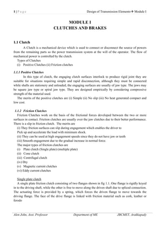
  • 1. 1 | P a g e Design of Transmission Elements Module I Alen John, Asst. Professor Department of ME JBCMET, Arakkapady MODULE I CLUTCHES AND BRAKES 1.1 Clutch A Clutch is a mechanical device which is used to connect or disconnect the source of powers from the remaining parts so the power transmission system at the will of the operator. The flow of mechanical power is controlled by the clutch. Types of Clutches (i) Positive Clutches (ii) Friction clutches 1.1.1 Positive Clutches In this type of clutch, the engaging clutch surfaces interlock to produce rigid joint they are suitable for situations requiring simple and rapid disconnection, although they must be connected while shafts are stationery and unloaded, the engaging surfaces are usually of jaw type. The jaws may be square jaw type or spiral jaw type. They are designed empirically by considering compressive strength of the material used. The merits of the positive clutches are (i) Simple (ii) No slip (iii) No heat generated compact and low cost. 1.1.2 Friction Clutches Friction Clutches work on the basis of the frictional forces developed between the two or more surfaces in contact. Friction clutches are usually over the jaw clutches due to their better performance. There is a slip in friction clutch. The merits are (i) They friction surfaces can slip during engagement which enables the driver to Pick up and accelerate the load with minimum shock. (ii) They can be used at high engagement speeds since they do not have jaw or teeth (iii) Smooth engagement due to the gradual increase in normal force. The major types of friction clutches are (i) Plate clutch (Single plate) (multiple plate) (ii) Cone clutch (iii) Centrifugal clutch (iv) Dry (v) Magnetic current clutches (vi) Eddy current clutches Single plate clutch A single plate friction clutch consisting of two flanges shown in fig 1.1. One flange is rigidly keyed in to the driving shaft, while the other is free to move along the driven shaft due to spliced connection. The actuating force is provided by a spring, which forces the driven flange to move towards the driving flange. The face of the drive flange is linked with friction material such as cork, leather or ferodo MOHAMMED FYZAL +918137088810
  • 2. 2 | P a g e Design of Transmission Elements Module I Alen John, Asst. Professor Department of ME JBCMET, Arakkapady Fig 1.1 Single plate clutch Torque transmitted by plate or disc clutch A friction disk of a single plate clutch is shown in above fig The following notations are used in the derivation Do = Outer diameter of friction disc (mm) Di = Inner diameter of friction disc (mm) P = pressure of intensity N/mm2 F = Total operating force (N) (Axial force) T = torque transmitted by friction (N-mm) Consider an elemental ring of radius r and radial thickness dr Area of elemental length = 2πr. dr Axial force length = 2πr r. P
  • 3. 3 | P a g e Design of Transmission Elements Module I Alen John, Asst. Professor Department of ME JBCMET, Arakkapady There are two criteria to obtain the torque capacity – uniform pressure and uniform wear 1. Uniform pressure Theory: In case of new clutches, un playing assumed to be uniformly distributed over the entire surface area of the friction disc. With this assumption, P is regarded as constant. Equation – 1 becomes Substituting the value of p from equation 3
  • 4. 4 | P a g e Design of Transmission Elements Module I Alen John, Asst. Professor Department of ME JBCMET, Arakkapady Torque transmitted by n- friction surfaces Axial force = Uniform Wear Theory: According to this theory, it is assumed that the wear is uniformly distributed over the entire surface of the friction disc. This assumption is used for workout clutches. The axial wear of the friction disc is in proportional to the frictional work. The work done by the frictional force (μ P) and rubbing velocity (2prN) where ‘N’ is speed in rpm. Assuming speed N and coefficient of friction ‘μ’ is constant for given configuration. Wear Pr Pr = constant C When clutch plate is new and rigid. The wear at the outer radius will be more, which will release the pressure at the outer edge due to the rigid pressure plate this will change the pressure distribution. During running condition, the pressure distribution is adjusted in such a manner that the product pressure is constant, C. From equation - (2)
  • 5. 5 | P a g e Design of Transmission Elements Module I Alen John, Asst. Professor Department of ME JBCMET, Arakkapady Substitute the value of C from equation – (7) Torque transmitted by “n” friction plates Maximum pressure occurs at inner radius Design considerations for friction clutches: 1. The suitable material forming the contact surfaces should be selected. 2. The moving parts of the clutch should have low weight in order to minimize the inertia load, especially in high speed service. 3. The clutch should not require any external force to maintain contact of the friction surfaces. 4. The provision for taking up wear of the contact surfaces must be provided. 5. The clutch should have provision for facilitating repairs 6. The clutch should have provision for carrying away the heat generated at the contact surfaces.
  • 6. 6 | P a g e Design of Transmission Elements Module I Alen John, Asst. Professor Department of ME JBCMET, Arakkapady 7. The projecting parts of the clutch should be covered by guard. Problem 1.1 A single plate friction clutch of both sides effective has 300 mm outer diameter and 160 mm inner diameter. The coefficient of friction 0.2 and it runs at 1000 rpm. Find the power transmitted for uniform wear and uniform pressure distributions cases if allowable maximum pressure is 0.08 Mpa. Solution: Given: i. Uniform wear theory
  • 7. 7 | P a g e Design of Transmission Elements Module I Alen John, Asst. Professor Department of ME JBCMET, Arakkapady ii. Uniform wear theory Power transmitted Problem 1.2 A car engine develops maximum power of 15 kW at 1000 rpm. The clutch used is single plate clutch both side effective having external diameter 1.25 times internal diameter μ = 0.3. Mean axial pressure is not to exceed 0.085 N/ mm2 . Determine the dimension of the friction surface and the force necessary to engage the plates. Assume uniform pressure condition. Solution Given:
  • 8. 8 | P a g e Design of Transmission Elements Module I Alen John, Asst. Professor Department of ME JBCMET, Arakkapady Multiple plate clutch Fig.1.2 shows a multiple plate clutch. The driving discs are splined to the driving shaft so that they are free to slip along the shaft but must rotate with it. The driven discs drive the housing by means of bolts along which they are free to slide. The housing is keyed to the driven shaft by a sunk key. In the clutch shown there are five pairs of friction surfaces. The driving discs may be pressed against the driven discs by a suitable mechanism so that the torque may be transmitted by friction between the discs.
  • 9. 9 | P a g e Design of Transmission Elements Module I Alen John, Asst. Professor Department of ME JBCMET, Arakkapady Fig.1.2 Multiple plate clutch Multi disc Clutch Equations derived for torque transmitting velocity of single plate are modified to account for the number of pairs of contacting surfaces in the following way. Where I = number of pairs of contacting surfaces. Where i = number of friction surfaces
  • 10. 10 | P a g e Design of Transmission Elements Module I Alen John, Asst. Professor Department of ME JBCMET, Arakkapady Problem 1.3 A multi plate clutch having effective diameter 250mm and 150mm has to transmit 60 kW at 1200 rpm. The end thrust is 4.5 kN and coefficient of friction is 0.08 calculate the number of plates assuming (i) Uniform wear and (ii) uniform pressure distribution on the plates. Solution Given: Problem 1.4 A multi plate clutch of alternate bronze and steel plates is to transmit 6 kW power at 800 rpm. The inner radius is 38 mm and outer radius is 70 mm. The coefficient of friction is 0.1 and maximum allowable pressure is 350 kN /m2 determine (i) Axial force required (ii) Total number of discs (iii) Average pressure and (iv) Actual maximum pressure
  • 11. 11 | P a g e Design of Transmission Elements Module I Alen John, Asst. Professor Department of ME JBCMET, Arakkapady Solution
  • 12. 12 | P a g e Design of Transmission Elements Module I Alen John, Asst. Professor Department of ME JBCMET, Arakkapady Cone clutch A simple form of a cone clutch is shown in fig.1.3, it consists of a driver or cup and the follower or cone. The cup is keyed to the driving shaft by a sunk key and has an inside conical surface or face which exactly fits the outside conical surface of the cone. The slope of the cone face is made small enough to give a high normal force. The cone is fitted to the driven shaft by a feather key. The follower may be shifted along the shaft by a forked shifting lever in order to engage the clutch by bringing the two conical surfaces in contact. Fig.1.3 Cone clutch Advantages: 1. This clutch is simple in design. 2. Less axial force is required to engage the clutch. Disadvantages: 1. There is a tendency to grab. 2. There is some reluctance in disengagement. Strict requirements made to the co-axiality of the shafts being connected.
  • 13. 13 | P a g e Design of Transmission Elements Module I Alen John, Asst. Professor Department of ME JBCMET, Arakkapady Torque transmitted by the cone clutch:-
  • 14. 14 | P a g e Design of Transmission Elements Module I Alen John, Asst. Professor Department of ME JBCMET, Arakkapady Substitutes the value of P from equation ---------- (3)
  • 15. 15 | P a g e Design of Transmission Elements Module I Alen John, Asst. Professor Department of ME JBCMET, Arakkapady If the clutch is engaged when one member is stationary and other rotating, then the cone faces will tend to slide on each other in the direction of an element of the cone. This will resist the engagement and then force. Problem 1.5 A cone clutch is to transmit 7.5 KW at 600 rpm. The face width is 50mm; mean diameter is 300mm and the face angle 15°. Assuming co efficient of friction as 0.2, determine the axial force necessary to hold the clutch parts together and the normal pressure on the cone surface.
  • 16. 16 | P a g e Design of Transmission Elements Module I Alen John, Asst. Professor Department of ME JBCMET, Arakkapady Problem 1.6 A friction cone clutch has to transmit a torque of 200 N-m at 1440 rpm. The longer diameter of the cone is 350mm. The cone pitch angle is 6.25°the force width is 65mm. the coefficient of friction is 0.2. Determine i) the axial force required to transmit the torque. ii) The average normal pressure on the contact surface when maximum torque is transmitted. Solution Given:
  • 17. 17 | P a g e Design of Transmission Elements Module I Alen John, Asst. Professor Department of ME JBCMET, Arakkapady Centrifugal clutch The centrifugal clutches are usually incorporated into the motor pulleys. It consists of a number of shoes on the inside of a rim of the pulley, as shown in Fig. Fig.1.4 Centrifugal clutch The outer surface of the shoes is covered with a friction material. These shoes, which can move radially in guides, are held against the boss (or spider) on the driving shaft by means of springs. The springs exert a radially inward force which is assumed constant. The weight of the shoe, when revolving causes it to exert a radially outward force (i.e. centrifugal force). The following procedure may be adopted for the design of a centrifugal clutch. 1. Mass of the shoes Consider one shoe of a centrifugal clutch as shown in Fig. Let m = Mass of each shoe, n = Number of shoes, r = Distance of centre of gravity of the shoe from the centre of the spider,
  • 18. 18 | P a g e Design of Transmission Elements Module I Alen John, Asst. Professor Department of ME JBCMET, Arakkapady R = Inside radius of the pulley rim, N = Running speed of the pulley in r.p.m., ω = Angular running speed of the pulley in rad / s = 2 π N / 60 rad/s, ω1 = Angular speed at which the engagement begins to take place, and μ = Coefficient of friction between the shoe and rim. We know that the centrifugal force acting on each shoe at the running speed, Pc = m.ω2 .r Since the speed at which the engagement begins to take place is generally taken as 3/4th of the running speed, therefore the inward force on each shoe exerted by the spring is given by 2. Size of the shoes
  • 19. 19 | P a g e Design of Transmission Elements Module I Alen John, Asst. Professor Department of ME JBCMET, Arakkapady 3. Dimensions of the spring Problem 1.7 A centrifugal clutch is to be designed to transmit 15 kW at 900 r.p.m. The shoes are four in number. The speed at which the engagement begins is 3/4th of the running speed. The inside radius of the pulley rim is 150 mm. The shoes are lined with Ferrodo for which the coefficient of friction may be taken as 0.25. Determine: 1. mass of the shoes, and 2. size of the shoes. Given: P = 15 kW = 15 × 103 W ; N = 900 r.p.m. ; n = 4 ; R = 150 mm = 0.15 m ; μ = 0.25 Solution: 1. Mass of the shoes 1.2 Brakes A brake is defined as a machine element used to control the motion by absorbing kinetic energy of a moving body or by absorbing potential energy of the objects being lowered by hoists, elevators, etc. The observed energy appears as heat energy which should be transferred to cooling fluid such as water or surrounding air. The difference between a clutch and a brake is that whereas in the former both the members to be engaged are in motion, the brake connects a moving member to a stationary member.
  • 20. 20 | P a g e Design of Transmission Elements Module I Alen John, Asst. Professor Department of ME JBCMET, Arakkapady 1.2.1 Block or shoe brake A is shown in fig 1.5. It consists of a short shoe which may be rigidly mounted or pivoted to a lever. The block is pressed against the rotating wheel by an effort Fat one end of the lever. The other end of the lever is pivoted on a fixed fulcrum O. The frictional force produced by the block on the wheel will retard the rotation of the wheel. This type of brake is commonly used in railway trains. When the brake is applied, the lever with the block can be considered as a free body in equilibrium under single-block brake the action of the following forces. 1. Applied force F at the end of the lever. 2. Normal reaction Fn between the shoe and the wheel. 3. Frictional or tangential braking force Fq between the shoe and the wheel. 4. Pin reaction. a = Distance between the fulcrum pin and the center of the shoe b = Distance between the center of the shoe to the end of lever where the effort is applied c = Distance between the fulcrum pin and the line of action of Fg Consider the following three cases; (i) Line of action of tangential force F0 passes through fulcrum Fig.1.5 Single-block brake
  • 21. 21 | P a g e Design of Transmission Elements Module I Alen John, Asst. Professor Department of ME JBCMET, Arakkapady In this case the actuating force is the same whether the direction of tangential force is towards or away from the fulcrum. (ii) Line of action of tangential force Fθ is in between the center of the drum and the fulcrum (a) Direction of Fθ is towards the fulcurm :
  • 22. 22 | P a g e Design of Transmission Elements Module I Alen John, Asst. Professor Department of ME JBCMET, Arakkapady Note: If the direction of F0 is towards the fulcrum, use the clockwise rotation formula and if the direction of F& is away from the fulcrum, use counter clockwise formula from the data handbook. When the angle of contact between the block and the wheel is less than 60°, we assume that the normal pressure is uniform between them. But when the angle of contact 2q is more than 60°, we assume that the unit pressure normal to the surface of contact is less at the ends than at the center and the wear in the direction of applied force is uniform. In such case we employ the equivalent coefficient of friction μ', which is given by.
  • 23. 23 | P a g e Design of Transmission Elements Module I Alen John, Asst. Professor Department of ME JBCMET, Arakkapady The brake is self -energizing when the friction force helps to apply the brake. If this effect is great enough to apply the brake with zero external force, the brake is called self-locking i.e., the brake is self locking when the applied force F is zero or negative. Problem 1.8 The block type hand brake shown in fig.1.6 has a face width of 45 mm. The friction material permits a maximum pressure of 0.6 MPa and a coefficient of friction of 0.24. Determine; 1. Effort F, 2. Maximum torque, 3. Heat generated if the speed of the drum is 100 rpm and the brake is applied for 5 sec. at full capacity to bring the shaft to stop. Fig.1.6 Given: Solution:
  • 24. 24 | P a g e Design of Transmission Elements Module I Alen John, Asst. Professor Department of ME JBCMET, Arakkapady Problem 1.9 A 400 mm radius brake drum contacts a single shoe as shown in fig a, and sustains 200 N-m torque at 500 rpm. For a coefficient of friction 0.25, determine: 1. Normal force on the shoe. 2. Required force F to apply the brake for clockwise rotation. 3. Required force F to apply the brake for counter clockwise rotation. 4. The dimension c required to make the brake self-locking, assuming the other dimensions remains the same. 5. Heat generated.
  • 25. 25 | P a g e Design of Transmission Elements Module I Alen John, Asst. Professor Department of ME JBCMET, Arakkapady Given: Solution: From the figure, the tangential force Fθ lies between the fulcrum and the center of drum. When the force Fθ acts towards the fulcrum (clockwise rotation), For anticlockwise rotation of the drum, the tangential force Fs acts away from the fulcrum as shown in figure. Problem 1.10 The layout of a brake to be rated at 250 N-m at 600 rpm is shown in figure. The drum diameter is 200 mm and the angle of contact of each shoe is 120°. The coefficient of friction may be assumed as 0.3 Determine. 1. Spring force F required to set the brake.
  • 26. 26 | P a g e Design of Transmission Elements Module I Alen John, Asst. Professor Department of ME JBCMET, Arakkapady 2. Width of the shoe if the value of pv is 2 N-m/mm2 -sec Given:
  • 27. 27 | P a g e Design of Transmission Elements Module I Alen John, Asst. Professor Department of ME JBCMET, Arakkapady 1.2.2 Band brakes A band brake consists of a band, generally made of metal, and embracing a part of the circumference of the drum. The braking action is obtained by tightening the band. The difference in the tensions at each end of the band determines the torque capacity. Simple band brakes: When one end of the band is connected to the fixed fulcrum, then the band brake is called simple band brake as shown in figure Let T1 = Tight side tension in N T2 = Slack side tension in N
  • 28. 28 | P a g e Design of Transmission Elements Module I Alen John, Asst. Professor Department of ME JBCMET, Arakkapady q = Angle of lap in radians μ = Coefficient of friction D = Diameter of brake drum in mm M1 = Torque on the drum in N-mm
  • 29. 29 | P a g e Design of Transmission Elements Module I Alen John, Asst. Professor Department of ME JBCMET, Arakkapady Problem 1.11 A simple band brake operates on a drum 0.6 m in diameter rotating at 200 rpm. The coefficient of friction is 0.25 and the angle of contact of the band is 270°. One end of the band is fastened to a fixed pin and the other end to 125 mm from the fixed pin. The brake arm is 750 mm long.
  • 30. 30 | P a g e Design of Transmission Elements Module I Alen John, Asst. Professor Department of ME JBCMET, Arakkapady (i) What is the minimum pull necessary at the end of the brake arm to stop the wheel if 35kW is being absorbed? What is the direction of rotation for minimum pull? (ii) Find the width of 2.4 mm thick steel band if the maximum tensile stress is not to exceed 55 N/mm2 . Given: D = 0.6 m = 600 mm, n = 200 rpm, p = 0.25, θ = 270°, a = 750 mm, b = 125 mm, N = 35kW, h = 2.4 mm, σd = 55 N/mm2
  • 31. 31 | P a g e Design of Transmission Elements Module I Alen John, Asst. Professor Department of ME JBCMET, Arakkapady Problem 1.12 In a simple band brake, the length of lever is 440 mm. The tight end of the band is attached to the fulcrum of the lever and the slack end to a pin 50 mm from the fulcrum. The diameter of the brake drum is 1 m and the arc of contact is 300°. The coefficient of friction between the band and the drum is 0.35. The brake drum is attached to a hoisting drum of diameter 0.65 m that sustains a load of 20 kN. Determine; 1. Force required at the end of lever to just support the load. 2. Required force when the direction of rotation is reversed. 3. Width of steel band if the tensile stress is limited to 50 N/mm2 .
  • 32. 32 | P a g e Design of Transmission Elements Module I Alen John, Asst. Professor Department of ME JBCMET, Arakkapady Given: a = 440 mm, b = 50 mm, D= 1 m = 1000 mm, Db = 0.65 m = 650 mm, q = 300°, μ = 0.35, W = 20kN = 20x 103 N, σd = 50N/mm2
  • 33. 33 | P a g e Design of Transmission Elements Module I Alen John, Asst. Professor Department of ME JBCMET, Arakkapady 1.2.3 Band and block brake: The band brake may be lined with blocks of wood or other material, as shown in Fig.1.8(a) Fig.1.8 Band and block brake Let T1 = Tension in the tight side, T2 = Tension in the slack side, μ = Coefficient of friction between the blocks and drum, T1' = Tension in the band between the first and second block, T2', T3' etc. = Tensions in the band between the second and third block, between the third and fourth block etc. Consider one of the blocks (say first block) as shown in Fig. (b). This is in equilibrium under the action of the following forces :
  • 34. 34 | P a g e Design of Transmission Elements Module I Alen John, Asst. Professor Department of ME JBCMET, Arakkapady 1. Tension in the tight side (T1), 2. Tension in the slack side (T1') or tension in the band between the first and second block, 3. Normal reaction of the drum on the block (RN), and 4. The force of friction (μ.RN). 1.2.4 Internal expanding shoe brake: An internal expanding brake consists of two shoes S1 and S2 as shown in Fig. 1.9 (a). Fig. 1.9 Internal expanding shoe brake
  • 35. 35 | P a g e Design of Transmission Elements Module I Alen John, Asst. Professor Department of ME JBCMET, Arakkapady The outer surface of the shoes are lined with some friction material (usually with Ferodo) to increase the coefficient of friction and to prevent wearing away of the metal. Each shoe is pivoted at one end about a fixed fulcrum O1 and O2 and made to contact a cam at the other end. When the cam rotates, the shoes are pushed outwards against the rim of the drum. The friction between the shoes and the drum Produces the braking torque and hence reduces the speed of the drum. This type of brake is commonly used in motor cars and light trucks. Consider the forces acting on such a brake, when the drum rotates in the anticlockwise direction as shown in Fig. (b). It may be noted that for the anticlockwise direction, the left hand shoe is known as leading or primary shoe while the right hand shoe is known as trailing or secondary shoe. Let r = Internal radius of the wheel rim. b = Width of the brake lining. P1 = Maximum intensity of normal pressure, PN = Normal pressure, F1 = Force exerted by the cam on the leading shoe, and F2 = Force exerted by the cam on the trailing shoe. Consider a small element of the brake lining AC θ at the centre. Let OA makes an angle θ with OO1 as shown in Fig. (b). The rate of wear of the shoe lining varies directly as the perpendicular distance from O1 to OA, i.e. O1B. From the geometry of the figure,
  • 36. 36 | P a g e Design of Transmission Elements Module I Alen John, Asst. Professor Department of ME JBCMET, Arakkapady
  • 37. 37 | P a g e Design of Transmission Elements Module I Alen John, Asst. Professor Department of ME JBCMET, Arakkapady Problem 1.13: Fig.1.9 shows the arrangement of two brake shoes which act on the internal surface of a cylindrical brake drum. The braking force F1 and F2 are applied as shown and each shoe pivots on its fulcrum O1 and O2. The width of the brake lining is 35 mm. The intensity of pressure at any point A is 0.4 sin θ N/mm2 , where θ is measured as shown from either pivot. The coefficient of friction is 0.4. Determine the braking torque and the magnitude of the forces F1 and F2. Fig.1.9 Given : b = 35 mm ; μ = 0.4 ; r = 150 mm ; l = 200 mm ; θ1 = 25° ; θ2 = 125° Solution:
  • 38. 38 | P a g e Design of Transmission Elements Module I Alen John, Asst. Professor Department of ME JBCMET, Arakkapady
  • 39. 39 | P a g e Design of Transmission Elements Module I Alen John, Asst. Professor Department of ME JBCMET, Arakkapady Assignment No. 1 1. A single plate clutch with both sides of the plate effective is required to transmit 25 kW at 1600 r.p.m. The outer diameter of the plate is limited to 300 mm and the intensity of pressure between the plates not to exceed 0.07 N/mm2 . Assuming uniform wear and coefficient of friction 0.3, find the inner diameter of the plates and the axial force necessary to engage the clutch. 2. A multiple disc clutch has radial width of the friction material as 1/5th of the maximum radius. The coefficient of friction is 0.25. Find the total number of discs required to transmit 60 kW at 3000 r.p.m. The maximum diameter of the clutch is 250 mm and the axial force is limited to 600 N. Also find the mean unit pressure on each contact surface. 3. An engine developing 22 kW at 1000 r.p.m. is fitted with a cone clutch having mean diameter of 300mm. The cone has a face angle of 12°. If the normal pressure on the clutch face is not to exceed 0.07 N/mm2 and the coefficient of friction is 0.2, determine : (a) the face width of the clutch, and (b) the axial spring force necessary to engage the clutch. 4. A single block brake, as shown in Fig. has a drum diameter of 720 mm. If the brake sustains 225 N-m torque at 500 r.p.m.; find : (a) the required force (P) to apply the brake for clockwise rotation of the drum; (b) the required force (P) to apply the brake for counter clockwise rotation of the drum; (c) the location of the fulcrum to make the brake self-locking for clockwise rotation of the drum; and The coefficient of friction may be taken as 0.3. 5. The drum of a simple band brake is 450 mm. The band embraces 3/4th of the circumference of the drum. One end of the band is attached to the fulcrum pin and the other end is attached to a pin B as shown in Fig. The band is to be lined with asbestos fabric having a coefficient of friction 0.3. The allowable bearing pressure for the brake lining is 0.21 N/mm2 . Design the band shaft, key, lever and fulcrum pin. The material of these parts is mild steel having permissible stresses as follows : σt = σc = 70 MPa, and τ = 56 MPa
  • 40. 40 | P a g e Design of Transmission Elements Module I Alen John, Asst. Professor Department of ME JBCMET, Arakkapady University Questions 1. A cone dutch is used to connect an electric motor running at 1440 r.p.m. with a machine that is stationary. The machine is equivalent to a rotor of mass 150 kg. and radius of gyration as 250 mm. The machine has to be brought to full speed of 1440 r.p.m. from a stationary condition in 40 seconds. The semi-cone angle is 12*. The mean radius of dutch is twice of the face width. The coefficient of friction is 0.2 and normal intensity of the pressure between contacting surface should not exceed 0.1 N/mm*. Assuming uniform wear criterion, calculate (a) The inner and outer diameters ; (b) The face width of the friction lining ; (c) The force required to engage the clutch ; and (d) The amount of heat generated during each engagement of clutch. (25 marks) 2. A single block brake with a torque capacity of 250 Nm. is shown in figure. The brake drum routes at 100 r.p.m. and coefficient of friction is 0.35. calculate (a) The actuating force and hinge-pin reaction for clockwise rotation of drum. (b) The actuating force and hinge-pin reaction for anti-clockwise rotation of drum. (c) The rate heat generated during braking action (d) The dimensions of the block if the intensity of the pressure between the Hock and the brake drum is 1 N/mm2 . The length of the block is twice its width- State whether the brake is self-locking. (25 marks)
  • 41. 41 | P a g e Design of Transmission Elements Module I Alen John, Asst. Professor Department of ME JBCMET, Arakkapady 3. (A) A centrifugal clutch is to be designed to transmit 15 KW at 900 rpm. The shoes are four in number. The speed at which engagement begin is ¾ the running speed. The inside radius of the pulley rim is 150 mm. The shoes are lined with Ferrodo for which the coefficient of friction may be taken as 0.25. Determine (a) Moss of the shoes. (b) Size of the shoes. (20 marks) (B) What are the basic design requirements of a clutch ? (5 marks) 4. (A) A double shoe brake as shown in figure is capable of absorbing a torque of 1400 N-m. The diameter of the brake drum is 350 mm. and the angle of contact for each shoe is 1000 . Assume intensity of pressure exerted on the shoe is 0.1 N/mm2 . If the coeffcient of friction between the brake drum mid lining is 0.4, find (a) The spring force necessary to lit the brake (b) The width of the brake shoes, if the bearing pressure on the lining material not to exceed 0.3 N/mm2 (20 marks) (B) Write a short note on types of brakes? (5 marks)
  • 42. 1 | P a g e Design of Transmission Elements Module II Alen John, Asst. Professor Department of ME JBCMET, Arakkapady MODULE II BEARINGS Syllabus Design of bearings - Types - Selection of a bearing type - bearing life - Rolling contact bearings - static and dynamic load capacity - axial and radial loads - selection of bearings - dynamic equivalent load - lubrication and lubricants - viscosity - Journal bearings - hydrodynamic theory - design considerations - heat balance - bearing characteristic number - hydrostatic bearings. 2.1 DESIGN OF BEARINGS 2.1.1 Bearing: When there is relative motion between machine members and when one of which supports the other. The supporting member is called a bearing. In engineering application, bearing act as supports, providing stability and free and smooth rotation. 2.1.2 Types of Bearings Bearings are classified into two categories  Sliding contact bearings  Rolling contact bearings or anti-friction bearings In sliding contact bearings, the relative motion between the members is sliding in nature. In rolling contact bearings, the relative motion between the parts is rolling in nature.
  • 43. 2 | P a g e Design of Transmission Elements Module II Alen John, Asst. Professor Department of ME JBCMET, Arakkapady 2.1.3 Types of sliding contact bearings  Slipper or guide bearings: In this type of bearing, the relative motion is Parallel to the sliding surfaces which may be flat. Example: - Lathe guide – ways or circular, Drilling machine spindles.  Journal bearing: In this type of bearing, relative motion between the parts is rotation and the load acts perpendicular to the shaft axis. It is used as supports for shafts. Example: - Crank pin and its bearing in a connecting rod, hoisting drum or loose pulley.  Thrust bearing: In this type of bearing, load acts parallel to the shaft axis, the supporting member are called a thrust bearing. There are two types Pivot bearing and collar bearing. Advantages and Disadvantages of rolling contact bearings Advantages  Friction is less  Ability to withstand momentary overloads without failure  Maintain accurate alignment of parts for a long period  Easy replacement  Require less or no attention  Occupy little axial space Disadvantages  High initial cost  Lower resistance to shock loading  Occupy more radial space 2.1.4 Types of Rolling contact bearings  Single row deep groove ball bearings: These are designed primarily for radial loads. It can also carry thrust loads in either direction.  Double row ball bearing: It can be made with radial or angular contact between the balls and races. It is narrower than two single row bearings. Load capacity is less than twice that of a single row bearing.
  • 44. 3 | P a g e Design of Transmission Elements Module II Alen John, Asst. Professor Department of ME JBCMET, Arakkapady  Angular contact ball bearing: In this type of bearing used to resist combined radial and thrust loads or heavy thrust loads depending on the contact angle.  Self – aligning ball bearing: In this type of bearing, the outer race is part of a hollow sphere which permits the bearing to have self – aligning property. In these two rows of balls are arranged in a zigzag manner.  Cylindrical roller bearing: In these use cylindrical rollers with approximately length to diameter ratio 1:1 to 1:3 as rolling elements. It is normally used for heavy radial loads.  Needle bearing: In this type of bearing, rollers are used whose length at least four times the diameter used where space is limited available with or without inner race.  Taper roller bearing: In these use rollers in the form of truncated cones. These can resist heavy loads in both axial and radial directions. It should not be used in high speed applications.
  • 45. 4 | P a g e Design of Transmission Elements Module II Alen John, Asst. Professor Department of ME JBCMET, Arakkapady  Spherical roller bearing: It contains two rows of rollers in barrel (spherical) shape. It can resist heavy radial loads and moderate thrust loads. It can be combined with the ability to row properly under conditions of mis– alignment.  Thrust ball bearing: In this type is designed to resist axial loads but not radial loads. Balls are placed between the grooved rings called washers. 2.2 BEARING MATERIALS 2.2.1 Properties (1) Should have sufficient strength & rigidity (2) Selection based on @ Compressive strength
  • 46. 5 | P a g e Design of Transmission Elements Module II Alen John, Asst. Professor Department of ME JBCMET, Arakkapady (b) Fatigue strength (c) conformability (d) embed ability (e) bond ability (f) Corrosion resistance (g) thermal conductivity (h) thermal expansion Babbitts Tin and lead-base babbitts are among the most widely used bearing materials. They have an ability to embed dirt and have excellent compatibility properties under boundary-lubrication conditions. In bushings for small motors and in automotive engine bearings, babbitt is generally used as a thin coating over a steel strip. For larger bearings in heavy-duty equipment, thick babbitt is cast on a rigid backing of steel or cast iron. Used where max bear press 7 to 14 N/mm2  .05 mm to .15 mm thick  tin base Tin 90%, Copper 4.5%, antimony 5% Lead 0.5%  Lead base lead 84%, tin 6% antimony 9.5%, copper 5% Cast iron Used with steel journals and where pressure limit 3.5 N/mm2, & speed 40m/mint Silver Used in aircraft engines, fatigue strength considered Non metallic bearings Carbon – graphite self lubricating dimensionally stable inert cam operate at high tamp Rubber Used with water like low viscosity Excellent for absorbing shock loads and vibrations Marine apply Wood Low cost, cleanliness, inflection to lubrication and anti-seizing are important Bronzes and Copper Alloys Dozens of copper alloys are available as bearing materials. Most of these can be grouped into four classes: copper-lead, lead-bronze, tin-bronze, and aluminum-bronze. Aluminum Aluminum bearing alloys have high wear resistance, load-carrying capacity, fatigue strength, and thermal conductivity; excellent corrosion resistance; and low cost. They are used extensively in connecting rods and main bearings in internal-combustion engines; in hydraulic gear pumps, in oil- well pumping equipment, in roll-neck bearings in steel mills; and in reciprocating compressors and aircraft equipment. Porous Metals Sintered-metal self-lubricating bearings, often called powdered-metal bearings, are simple and low in cost. They are widely used in home appliances, small motors, machine tools, business machines, and farm and construction equipment.
  • 47. 6 | P a g e Design of Transmission Elements Module II Alen John, Asst. Professor Department of ME JBCMET, Arakkapady Plastics Many bearings and bushings are being produced in a large variety of plastic materials. Many require no lubrication, and the high strength of modern plastics lends to a variety of applications. Bearingmaterials Fatiguestrength Conformability Embed-ability Anti-scoring Corrosion Resistance Thermal Conductivity Tin base Habbit Poor Good Excellent Excellent Excellent Poor Lead base Habbit Poor to fair Good Good Good to Excellent Fair to Good Poor Lead Bronze Fair Poor Poor Poor Good Fair Silver Excellent At none Poor Poor Excellent Excellent 2.3 SELECTION OF A BEARING TYPE 1) For low and medium radial loads, ball bearings are used, whereas for heavy loads and large shaft diameters roller bearings are selected. 2) Self-aligning ball bearings and spherical roller bearings are used in applications where a misalignment between the axis of shaft and housing is likely to exist. 3) Thrust ball bearings are used for medium thrust loads whereas for heavy thrust loads, cylindrical roller thrust bearings are recommended. Double acting thrust bearings can carry the thrust load in either direction. 4) Deep groove ball bearings, angular contact bearings and spherical roller bearings are suitable in applications where the load acting on the bearing consists of two components - radial and thrust. 5) The maximum permissible speed of the shaft depends upon the temperature rise in the bearing. For high speed applications, deep groove ball bearings, angular contact bearings and cylindrical roller bearings are recommended. 6) Rigidity controls the selection of bearing in certain applications like machine tool spindles. Double row cylindrical roller bearings or taper roller bearings are used under these conditions. The line of contact in these bearings, as compared with the point of contact in ball bearings, improves the rigidity of the system. 7) Noise becomes the criterion of selection in applications like house hold appliances. For such applications, deep groove ball bearings are recommended. Step 1: Calculate the radial and axial forces acting on the bearing and determine the diameter of the shaft where the bearing is to be fitted. Step 2: Select the type of bearing for the given application (PSG DDB Page no. 4.1)
  • 48. 7 | P a g e Design of Transmission Elements Module II Alen John, Asst. Professor Department of ME JBCMET, Arakkapady Step 3: Determine the values of X and Y, the radial and thrust factors from data book page no. 4.4. The value depends upon two ratios Fa /Fr and Fa/C0, where C0 is the static load capacity. Step 4: Calculate the equivalent dynamic load from the equation, P = (XFr + YFa) S (DDB Page no. 4.2) Step 5: Make decision about the expected bearing life and express the life L10 in million revolutions. (DDB Page no. 4.5) Step 6: Calculate the dynamic load capacity from the equation, C = P (L10)1/3 (DDB Page no. 4.2) Step 7: Check whether the selected bearing of series 60 has the required dynamic capacity. If not, select the bearing of the next series and go back to step 3 and continue. 2.4 BEARING LIFE Life of an individual ball bearing is defined as the total number of revolutions or the number of hours at a given constant speed of bearing operation required for the failure criteria to develop. 2.4.1 Rating Life or Minimum life or L10 life Rating Life or Minimum life or L10 life of a group of apparently identical ball or roller bearings is defined as the number of revolutions or hours at some given constant speed that 90% of a group of bearings will complete or exceed before the failure criteria’s develop. 2.4.2 Average Life or Median life When groups consisting of large number of bearings are tested to failure the median life’s of the groups are averaged and the life is do not end between the average life or median life. 2.5 ROLLING CONTACT BEARINGS 2.5.1 Static load capacity (C0) The load that can be resisted by a bearing under static condition is known as static load carrying capacity ( Static load rating). It produces permanent deformation in the rolling elements and races. The permissible static load depends on the permissible permanent deformation of rolling elements and races. 2.5.2 Dynamic load capacity (C) The dynamic load carrying capacity is based on the fatigue life of the bearing. Dynamic load carrying capacity (Dynamic load rating) is defined as the radial load in case of roller bearings or thrust load in case of thrust bearings, that can be resisted for a minimum life of 106 revolutions. 2.5.3 Dynamic Equivalent Load The equivalent dynamic load is defined as the constant radial load in radial bearings (thrust load in thrust bearings) , that if applied to the bearing will attain under actual condition of forces. Equivalent dynamic load, P = XVFr + YFa Where, P - Equivalent dynamic load (N) Fr - Radial load (N) Fa - Axial or thrust load (N) V - Race rotation factor X and Y - Radial and Thrust factors
  • 49. 8 | P a g e Design of Transmission Elements Module II Alen John, Asst. Professor Department of ME JBCMET, Arakkapady The race rotation factor depends upon whether the inner race is rotating or the outer race is stationary. The value of V is one, when the inner race rotates while the outer race is held stationary in the housing. The value of V is 1.2, when the outer race rotates with respect to load, while the inner race remains stationary. 2.6 LUBRICANT The lubricants are used in bearings to reduce friction b/w t he rubbing surfaces and to carry away the heat generated by friction. All lubricants are classified into three. 1. Liquid 2. Semi-Liquid 3. Solid Properties : 1. Viscosity 2. Oiliness 3. Density 4. Viscosity Index 5. Flash point 6. Fire point 2.6.1 Seals for Grease Lubrication In order that ball or roller bearings may operate properly, they must be protected against loss of lubricant and entrance of dirt and dust on the bearing surfaces. In its simplest and least space-requiring form, this is accomplished in some types of bearings by the use of a thin steel shield on one or both sides of the bearing, fastened in a groove in the outer ring and reaching almost to the inner rings as illustrated in Fig. All other types of bearings require a seal between the bearing housing and the shaft; the types and designs of which are shown in Fig. Fig-Housing seals for grease lubrication.
  • 50. 9 | P a g e Design of Transmission Elements Module II Alen John, Asst. Professor Department of ME JBCMET, Arakkapady 2.6.2 Seals for Oil Lubrication With oil lubrication, the sealing devices have the double function of protecting the bearing against contamination and retaining the lubricant in the housing. Protection is obtained by means of friction seals or fingers, as when grease lubrication is used. The essential feature for retaining the oil is a groove in the rotating shaft, or a rotating ring or collar from whose edges the oil is thrown by centrifugal force. The oil-groove seal shown in given Fig. retains the oil effectively but should be used only in dry and dust-free places where there is little danger of contamination. This Figure shows examples of labyrinth seals, which retain the oil and protect against contamination. 2.7 PETROFF’S EQUATION The phenomenon of bearing friction was first explained by Petroff on the assumption that the shaft is concentric. Though we shall seldom make use of Petroff’s method of analysis in the material to follow, it is important because it defines groups of dimensionless parameters and because the coefficient of friction predicted by this law turns out to be quite good even when the shaft is not concentric. Let us now consider a vertical shaft rotating in a guide bearing. It is assumed that the bearing carries a very small load, that the clearance space is completely filled with oil, and that leakage is negligible (Fig. 12–3). We denote the radius of the shaft by r, the radial clearance by c, and the length of the bearing by l, all dimensions being in inches. If the shaft rotates at N rev/s, then its surface velocity is U = 2πr N in/s. Since the shearing stress in the lubricant is equal to the velocity gradient times the viscosity, from Eq. we have (a) where the radial clearance c has been substituted for the distance h. The force required to shear the film is the stress times the area. The torque is the force times the lever arm r. Thus (b) If we now designate a small force on the bearing by W, in pounds-force, then the pressure P, in
  • 51. 10 | P a g e Design of Transmission Elements Module II Alen John, Asst. Professor Department of ME JBCMET, Arakkapady pounds-force per square inch of projected area, is P = W/2rl . The frictional force is f W, where f is the coefficient of friction, and so the frictional torque is (c) Substituting the value of the torque from Eq. (c) in Eq. (b) and solving for the coefficient of friction, we find (e) The above equation (e) is called Petroff ’s equation and was first published in 1883. The two quantities μN/P and r/c are very important parameters in lubrication. Substitution of the appropriate dimensions in each parameter will show that they are dimensionless. The bearing characteristic number, or the Sommerfeld number, is defined by the equation The Sommerfeld number is very important in lubrication analysis because it contains many of the parameters that are specified by the designer. Note that it is also dimensionless. The quantity r/c is called the radial clearance ratio. If we multiply both sides of Eq. (e) by this ratio, we obtain the interesting relation Figure a Petroff’s lightly loaded journal bearing consisting of a shaft journal and a bushing with an axial- groove internal lubricant reservoir. The linear velocity gradient is shown in the end view. The
  • 52. 11 | P a g e Design of Transmission Elements Module II Alen John, Asst. Professor Department of ME JBCMET, Arakkapady clearance c is several thousandths of an inch and is grossly exaggerated for presentation purposes. 2.8 HYDRODYNAMIC JOURNAL BEARING D  Diameter of bearing d  Diameter of journal l  Length of bearing 1. Diameteral clearance : It is the difference between the diameters of the bearing and journal. C - D - d 2. Radial clearance : It is the difference between the radie of bearing and journal. 1 D d C R r 2      C 2 3. Eecentricity : It is the radical distance between the centre (o) of the bearing and the displaced centre(o’) of the bearing under load. 4. Short and long bearing: If the ratio of the length to diameter of the journal (i.e., l d ) (i) Minimum Oil Film Thickness. It determines the closest approach of the journal and the bearing surfaces with complete lubrication. Its value depends upon the degree of finish of these surfaces and the rigidity of the journal and bearing construction, and on the size and kind of the dirt particles present in the oil. If the bearing construction is quite rigid and if the oil is kept clean, then the minimum oil film thickness for hydrodynamic lubrication, must be equal to or greater than the sum of the average peak to valley roughness of the journal and bearing surface i.e.  0 p B Jh C rms rms  Cp = roughness peak factor = ratio of peak to average roughness B Jrms ,rms To take into account, the dirt particles, shaft deflection, etc., a factor called “clearance factor” is incorporated to increase the specified minimum film thickness, so  0 e p B Jh C .C . rms rms  , where Ce = clearance factor. For ordinary Babbitt lined bearings the film thickness should not be less than 0.02 mm. On larger power machinery, the minimum film thickness may be limited to 0.025 to 0.15 mm. one rule of the thumb is to limit the minimum film thickness to 0.00025D. It has been found by investigators that, for bearings of certain geometry, the minimum oil film thickness is a function of Bearing Modulus or Bearing service characteristic number (defined ahead as equal to Zn/p), that is,  0h Zn / p  0h Z  n
  • 53. 12 | P a g e Design of Transmission Elements Module II Alen John, Asst. Professor Department of ME JBCMET, Arakkapady 1/ p  For hydro-dynamic lubrication to occur. 1. Wedge-shaped gap should be formed between the sliding surfaces. 2. A lubricant of adequate viscosity should continually be introduced into the gap. 3. The relative speed of the journal should be enough to create the hydro-dynamic pressure in the fluid film necessary to balance the external load. 2.8.1 Roughness Peak Factor Cp Metallic Finish Average Value, Cp Typical range, Cp Ground 4.5 3.5 – 5.0 Hydrolapped 6.5 5.5 – 7.5 Loose abrasive lapped 10.0 7.5 – 13.0 Sand papered 7.0 5.5 – 9.0 Super finished 7.0 5.5 – 9.5 Turned 5.0 3.5 – 8.0 2.8.2 Bearing Surface Roughness Type of surface Surface Roughness High Precision Journal 0.125 – 0.2 High Precision Bearing 0.125 – 0.5 Medium Precision Journal 0.4 Medium Precision Bearing 0.8 Commercial Grinding 0.4 – 1.6 Broaching, Reaming, Boring, Finish Turning 0.8 – 1.6 (ii) Bearing Modulus: It is designated as “C” and is defined as; Bearing Modulus = Zn p (8) The bearing modulus is of special interest in bearing design. Its variation with co-efficient of friction is shown in Fig. For any given bearing, there is a value for bearing modulus indicated by C, for which the co-efficient of friction is minimum. The bearing should not be operated at this value of bearing modulus, since a slight decreases in speed or a slight increase in pressure will make the journal
  • 54. 13 | P a g e Design of Transmission Elements Module II Alen John, Asst. Professor Department of ME JBCMET, Arakkapady to operate in the partial lubrication state resulting in high friction, heating and wear. To prevent this, the average value of Bearing modulus should be, Zn 3C p  The values of C are given in Table . p is in MPa For large fluctuations and heavy impact loads, Zn 15 C p  The design data for Journal bearings is listed in Table Values of C Shaft Bearing C Hardened and ground steel Babbitt 2.85 Machined soft steel Babbitt 3.60 Hardened and ground steel Plastic Bronze 4.30 Machined soft steel Plastic Bronze 5.00 Hardened and ground steel Rigid Bronze 5.70 Machined soft steel Rigid Bronze 7.00 Design Data for Journal Bearings Bearing Types p MN/m2 Z kg/ms Zn p dC D L D Axles: Locomotive 3.85 0.600 4.5 – 7.35 0.001 max. 1.6 – 1.8 Railway Car 2.1 – 3.5 0.500 7.00 – 14.30 0.001 max. 1.8 – 2.0 Crankpins: Aircraft 5.25 – 35 0.008 1.5 - 0.5 – 1.5 Automobile 10.5 – 24.5 0.008 1.5 0.001 max. 0.5 – 1.4
  • 55. 14 | P a g e Design of Transmission Elements Module II Alen John, Asst. Professor Department of ME JBCMET, Arakkapady Diesel 10.35 – 28 0.020 – 0.060 0.75 – 1.43 0.001 0.8 – 1.5 Gas 8.4 – 12.6 0.020 – 0.60 1.43 – 2.85 0.001 0.8 – 1.5 Steam (HS) 2.8 – 8.4 0.030 0.85 – 2.14 0.001 max. 1 Steam (LS) 5.6 – 1.5 0.080 0.85 – 1.14 0.001 max. 1 – 1.25 Shears, Punches 35 – 56 0.100 - 0.001 1- 2 Crank shaft, main bearing Aircraft 4.2 – 12.6 0.025 – 0.030 2.25 – 3.00 0.001 max. 0.6 – 1.5 Automobile 2.1 – 12.6 0.025 – 0.0030 2.85 – 4.30 0.001 max 0.8 – 1.5 Diesel 2.45 – 8.4 0.022 – 0.060 2.14 – 2.85 0.001 max 0.8 – 1.5 Gas 3.5 – 7 0.020 – 0.060 2.85 – 4.30 0.001 max. 0.4 – 2.4 Steam (HS) 0.42 – 3.5 0.15 – 0.030 3.60 – 4.30 0.001 max. 1.3 – 1.7 Steam (LS) 0.56 – 2.8 0.070 2.85 – 4.30 0.001 max. 1.2 – 1.6 Shears, Punches 14.0 – 28.0 0.100 - 0.001 1-2 Wrist Pins: Aircraft 20-70 0.007-0.008 1.14-2.14 0.001 max 0.6-1.5 Automobile 10.5-35 0.007-0.008 1.14-2.14 0.001 max. 0.8-1.5 Diesel 8.4-12.6 0.020-0.060 2.85-3.60 0.001 max. 0.8-1.4 Gas 8.4-14 0.020-0.060 0.75-1.43 0.001 max. 0.8-1.25 Steam (HS) 10.5-12.6 0.025 0.75 0.001 1.4-1.6 Steam (LS) 7-10.5 0.070 0.75 0.001 1.2-1.5 Generators 0.7 – 1.4 0.025 28.50 0.001 1-2 Motors Pumps Line shafts 0.105 – 1.05 0.025-0.060 4.30-14.30 0.001 2.5-3 Reducing Gears 0.56-17.5 0.030-0.050 5.70-43.00 0.001 2-4
  • 56. 15 | P a g e Design of Transmission Elements Module II Alen John, Asst. Professor Department of ME JBCMET, Arakkapady Machine Tools 0.35 – 2.1 0.040 0.3 – 1.43 0.001 1-3 Steam Turbines 0.55-2.1 0.010-0.20 14.30-28.50 0.001 1-2 Rolling mills 21 0.050 14.30 0.0015 1.1-1.5 (iii) Sommerfeld number or Bearing Characteristic Number: This is also a very useful number in the design of sleeve bearings. It is defined as: 2 d Zn D S p C        2. Fig. shows the graphs of the minimum film ratio 0 r h c versus Sommerfeld number, S for bearings having various length diameter ratio L D . These graphs can be easily used for the design of sleeve bearings. For example, corresponding to a known minimum permissible oil film thickness h0 and an assumed radial clearance Cf a specific value of S can be obtained. Then if certain quantities in Eqn. (17.9) are known, the remaining can be found out. Curves showing variation of co-efficient of friction variable, oil flow variable, Temperature rise variable are also available. (iv) Operating pressures: The minimum operating pressure known as “critical pressure” is the pressure at which the oil film breaks down and metal to metal contact begins. It is given empirically as: 2 2 6 d Zn D L p . .MN / m c D L4.75 10              (10) In the above equation, it is assumed that d 0 C h 4  (v) Coefficient of Friction: The co-efficient of friction is of great significance in bearing design. Its value can’t be determined very accurately since the degree of lubrication is generally not known. For self contained full bearings, for hydrodynamic lubrication, the co-efficient of friction is given empirically as: f6 d 0.326 Zn D f . k p C10            (11) Where kf = factor to correct for end leakage. Its value varies with L D Ratio. Its value may be taken as 0.002 for L 0.75 2.8 D   . Its value can also be found out from Fig. For pressure fed hydrodynamic bearings, and hydrostatic bearings, the correction factor is not considered, and, therefore, the co-efficient of friction is given as:
  • 57. 16 | P a g e Design of Transmission Elements Module II Alen John, Asst. Professor Department of ME JBCMET, Arakkapady 6 d 0.326 Zn D f . p C10           The co-efficient of friction for these conditions, is generally below than 0.001. For lightly loaded bearings, the co-efficient of friction may be approximately calculated from petroff’s equation: 2 d Zn D f 30 p C            (13) here p is N/m2. When the bearing operate at boundary lubrication or partial lubrication conditions, the values of ‘f’ may be taken from table, which is due to Fuller. Co-efficient of friction for partial lubrication conditions Condition f Boundary lubricated, regularly attended 0.02 – 0.08 Bearing dried out containing a bare film of oil 0.08 – 0.14 Bearing completely dry with contamination and burned off 0.25 – 0.40 (vi) Heating of Bearings: The factional work is converted into heat- This heat must be dissipated from the bearing house to avoid its overheating because at high temperatures the oil viscosity will decrease, making the oil to squeeze out resulting in negligible lubrication and consequently seizing of the bearing. The usual operating temperature for bearings varies from 50 to 80°C, The heal generated due to friction is given as : Hg = f . F. V watts where F = load in N = pLD, p in N/m2, L and D in m. and V = Rubbing velocity, m/s f will correspond to the type state of lubrication. Dn V 60   Heat generated is: f Dn H f .F. watts 60   (14) After thermal equilibrium, the heat will be dissipated at the same rate at which it is generated. The heat dissipation will depend upon the method of lubrication (a) Self-contained bearings: In such bearings, the heat generated in the oil will be transmitted to the bearing body from where it must be dissipated into the surrounding area. The amount of heat dissipated will depend upon the temperature difference, size and mass of the radiating surface, and on the air flow around the bearing. The rate of heat dissipation is given as :
  • 58. 17 | P a g e Design of Transmission Elements Module II Alen John, Asst. Professor Department of ME JBCMET, Arakkapady Hd = kd DL(tb – ta) (15) where tb = temperature of bearing oC ta = temperature of surrounding, oC where kd = energy dissipation co-efficient, W/m2oC Table 14. 2.9 ENERGY DISSIPATION COEFFICIENT Bearing Condition kd 1) Simple Pillow – block bearings: Quiet Air Air at 2.5 m/s 146.56 to 244.23 488.50 to 767.60 2) Heavy duty self aligning ring-oil lubricated: Quiet Air Air at 2.5 m/s 293.00 to 390.77 879.23 to 1228.13 The bearing temperature tb is frequently assumed to be the mean between the average oil temperature t0 and the temperature of surroundings i.e. For usual industrial applications, the upper limit of permissible oil temperatures ranges from 70°C to 1°.C. If the temperature is higher, bearing is cooled by water circulating through oils built in the bearing or sing pressure feeding of the lubricant. (b) Pressure Fed Bearings: The amount of heat removed by the circulating oil is: H0 =  . (t0 . te), watts *17) where  = density of oil = 900 kg/m3.  = specific heat of oil = 1.84 to 2.05 kJ/kgoC Q = quantity of oil, m3/s t0 – te = outlet temperature of oil – entrance temperature of oil) oC The average oil film temperature may be taken as:  a e 0 e 1 t t t t 2    The upper limit of the permissible oil temperature for usual industrial applications ranges from about 70° to 82Q C. If this temperature is exceeded, either the oil feed pressure or oil viscosity must be changed. The oil '' is usually circulated through the bearings at pressures ranging from 0.07 to 0.7 N/mm2. Another method to avoid overheating of oil is to circulate 3 to 5 times the amount of oil calculated from the equation (17.17). Design Procedure: There is no one design procedure for the design of journal bearings. There can be unlimited design procedures. Sommerfeld number, as discussed earlier, may be used for the bearing design. The design usually involves : 1. Optimising clearance.
  • 59. 18 | P a g e Design of Transmission Elements Module II Alen John, Asst. Professor Department of ME JBCMET, Arakkapady 2. Optimizing bearing length, lubricating inlet slots, and 3. Calculation of energy balance. Before we give the design procedure, the following design considerations should be kept in mind : - 1. Lubricants: The lubricant to be used can be either liquid, solid or gas. The choice will depend upon such factors as type of machine, method of lubricant supply and load characteristics. 2. Bearing load: The load coming on a bearing is usually specified. However, its value per projected area can be determined by suitably selecting length and diameter of the bearing. The value of load per projected area will depend upon the bearing life desired. It is clear that smaller the load per projected area, the greater the bearing life and vice versa. 3. Length to Diameter Ratio: This is a very important parameter in bearing design. Its value lies between 0.8 and 1.5, with a value of unity being most common. Long bearing (L/D ratio greater than 1) is used where misalignment must be avoided and a reduced load carrying capacity can be tolerated, In short bearings (L/D<1), the danger of metal to metal contact due to large shaft deflections is greatly reduced. So, a rought rule | for choosing a L/D ratio is: (i) Use preferably, L/D =1.0 (ii) Use L/D<1 .0, if, deflections are expected to be severe (ii) Use L/D>1 .0, if shaft alignment is important 4. Clearance: The value of journal bearing clearance depends on: materials, manufacturing accuracy, load carrying capacity, minimum film clearance, oil flow, film temperature etc. Large clearance will allow foreign material to pass-easily through the bearing, the increased oil flow will reduce film temperature and thus increase the bearings life. But a large clearance will result in a loose, noisy bearing and a resulting decrease in minimum film thickness. A reasonable clearance ratio (Cd/D) equal to 0.001 is most common. When the bearing load, the diameter and speed of the shaft are known, the following design procedure may be followed: 2.9 DESIGN PROCEDURE FOR JOURNAL BEARING When the bearing load, the diameter and speed of the shaft are known the following design procedure may be followed. (1) Determine the bearing length by choosing a ratio of l d (2) Check the bearing pressure F P ld  from table for probable sales factory value (3) Assume a clearance ratio cd d from table (4) Assume a lubricant ail from table, and its operating temp, the ranged which has already been mentioned from graph find the value of Z corresponding to the operating temp. assumed for the selected oil.
  • 60. 19 | P a g e Design of Transmission Elements Module II Alen John, Asst. Professor Department of ME JBCMET, Arakkapady (5) Find nZ P and check this value with corresponding values in table to determine the possibility of maintaining fluid film lubrication. (6) Determine coefficient of friction (7) Determine heat generated (8) Determine hat drum palled (9) Determine the thermal equilibrium to see that heat dissipated become at least equal to heal generated. 2.10 SOLID JOURNAL BEARING It is the simplest form of journal bearing. It is simply a block of CI with a hole for a shaft providing running fit. 2.10.1 Bushed Bearing : This is an improved solid bearing in which a bush of bran or gun metal is provided. The outside of the brush is a driving fit in the hole of the casting where as the inside is a running fit for the shaft when the bush gets worn out, it can be easily replaced. In small bearing the frictional force itself holds the bush in position but for shaft transmitting high power, are used for the prevention of rotation and sliding bush. 2.10.2 Design of Bearing Caps and Bolts : When a split bearing is used, the bearing cap is tightened on the top. The load is usually carried by the bearing and not the cap, but some cases eg, split connecting rod end on double acting steam engines, a considerable load comes on the cap of the bearing. Example 2.1 A journal bearing is proposed for a centrifugal pump. The diameter of the journal is 0.15 m and the load on it is 40 kN and its speed is 900 rev/min. Complete the design calculation for the bearing. Solution: 1. Diameter of the journal, D = 0.15 m From table 12, L D ratio for pumps varies from 1 to 2. Let us take L 1.6 D  2. Bearing pressure, F 40 1000 p 1.11MPa LD 0.24 0.15      From table 12, the pressure is within the usual limits of 0.7 to 1.4 MPa for pumps. 3. Selecting turbine oil of ring oiled bearings from Table 7. Let us assume the operative temperature of oil film as 55oC. From fig. the absolute viscosity of oil at this temperature is: Z = 0.018 Ns/m2.
  • 61. 20 | P a g e Design of Transmission Elements Module II Alen John, Asst. Professor Department of ME JBCMET, Arakkapady Zn 0.018 900 14.59 p 1.11     From table 12, the operating value of Zn 28.50 p  As already indicated, the minimum value of bearing modulus at which the oil film will break is given as: Zn 3C 28.50 p   minimum point of friction = 9.50 Since the calculated value of bearing modulus 14.59 is more than 9.50, it is clear from Fig., that the bearing will operate under hydrodynamic conditions. 4. Now co-efficient of friction is given as: 2 f6 0.326 Zn D f k , p is in MN / m p Cd10           Now from table 17.12, Cd 0.0001 D  Now from Fig. for f L 1.6, k 0.0024 D   3 6 0.326 f 14.59 10 0.0024 0.0072 10       5. Heat generated = f . F.V. watts. Dn 0.15 900 V 7.07 m /s 60 60       3 Hg 0.0072 40 10 7.07 2036.16W      6. Heat dissipated  d d b aH k LD t t  watts Now from table 14, let us take, kd = 1228.13 Now from eqn. (16)     o b a 0 a 1 1 t t t t 55 15.5 19.75 C 2 2       dH 1228.1 0.24 0.15 19.75 873.20W      Since the heat dissipated is less than the heat generated, the bearing should be redesigned by making changes in the assumed values for oil temperature, viscosity and clearance ratio, or the bearing should be cooled artificially by water. Let us assume t0 = 65oC From Fig., Z = 0.0124 Ns/m2
  • 62. 21 | P a g e Design of Transmission Elements Module II Alen John, Asst. Professor Department of ME JBCMET, Arakkapady Zn 0.0124 900 10.054 9.50 O.K. p 1.11       Now let us take the correction factor fk 0.002 , and Cd 0.0015 D  4 6 0.26 10 f 10.054 0.002 0.00412 1510       3 Hg 0.0042 40 10 7.07 1165.14W      Now,   o b a 1 t t 65 15.5 24.75 C 2     Hd 1228.13 0.24 0.15 24.75     = 1094.26 W, therefore, not much difference. Example 2.2: Design a bearing and journal to support a load of 4500 N at 600 rev/min using a hardened steel journal and a bronze backed babbitt bearing. The bearing is lubricated by oil rings. Take room temperature as 21oC and the oil temperature as 80oC./ Solution: 1. Let us assume the oil as light transmission oil corresponding to curve 2, in Z 0.01 kg / ms  2. From Table 11, the minimum bearing modulus for the given journal and bearing is Therefore, operating Zn p is given as: Zn 3 2.85 8.55 p    p 0.702MPa  3. Required Projected area, 2 6 F 4500 L D 0.00641m p 0.702 10      Let us take L = D 2 D 0.00641  D 80 mm  L 80 mm  Actual bearing pressure, 4500 p 0.703MPa 0.08 0.08    4. Now the permissible pressure for film lubrication is given as: 2 6 Zn D L p Cd D L4.75 10               Let us take dC 0.001 D 
  • 63. 22 | P a g e Design of Transmission Elements Module II Alen John, Asst. Professor Department of ME JBCMET, Arakkapady 6 6 0.01 600 0.08 p 10 0.6316MPa 0.08 0.084.75 10       which is less than the actual working pressure, therefore, the bearing will work under film lubrication. 5. Now f6 d 0.326 Zn D f k p C10     6 0.326 0.01 600 1000 0.002 0.004815 0.70310       6. Heat generated, gH fFV watts 80 600 V 2.51 m /s 1000 60     gH 0.004815 4500 2.51 54.39W     7. Heat dissipated.  d d b aH k D.L t t  Now   o b a 1 t t 80 21 29.5 C 2     Let us take dk 390.77 for still air. dH 390.77 0.08 0.08 29.5 73.78W      Since Hd > Hg 2.11 ROLLING CONTACT BEARINGS (ANTIFRICTION BEARINGS) 2.11.1 Static Equivalent load [Po] The static equivalent load may be defined as the static radial load or axial load which if applied would cause the same total permanent deformation at the most heavily stressed ball and race contact as that which occurs under the actual condition of loading [is under combined radial & axial or thrust loads) 2.11.2 Statically Loaded Bearings. The bearings which do not rotate or rotate at a very small speed (n < 1 rev/, min) are called as statically loaded. An example of a 'stationary radial load', one that does not rotate, acts in a constant direction is the belt load. The limiting load of such bearings is determined by the magnitude of the permanent deformation of the contact surfaces, and not by the service life of the bearing parts. The earliest* work on rolling element bearings was carried out by Hertz and Striebeck. The maximum load which would be carried by a ball is given by the formula : r 0 4.37F P z  (29)
  • 64. 23 | P a g e Design of Transmission Elements Module II Alen John, Asst. Professor Department of ME JBCMET, Arakkapady where Fr = radial load on the bearings z = number of balls in the bearing In this formula, it has been assumed that there is no radial clearance between balls and races. Radial clearance has marked effect on the load distribution between balls and on the magnitude of P0. For this reason, the above equation is modified as: r 0 5F P z  (30) The basis static load rating “C0” which corresponds to a total permanent deformation of ball and race, at the most heavily stressed contact point, equal to 0.0001 times the ball diameter, is given by the following formula: 2 0 0C f . i . zD . cos  (31) where i = number of rows of balls in any one bearing. z = number of balls per row D = Ball diameter f0 = a factor. In (N.m) units, its values are: = 3.34 × 10⁶ for self aligning ball bearings. = 12.26 × 10⁶ for radial contact and angular contact ball bearings. If the bearing is under the combined radial and thrust loads, the static equivalent load P0 shall be the greatest of those obtained from the following formulas: 0 0 r 0 aP X .F Y .F  0 rP F where 0X = a radial factor Y0 = a thrust factor Fr = radial load Fa = thrust load. The values of X0 and Y0 are given in Table. The equivalent load is defined as that hypothetical load which, if applied, will have the same effect on bearing life as the actual loads. Bearing Type Single row bearing Double row bearing X0 Y0 X0 Y0 Radial contact groove ball bearings 0.6 0.5 0.6 0.5 α = 20o 0.5 0.42 1 0.84
  • 65. 24 | P a g e Design of Transmission Elements Module II Alen John, Asst. Professor Department of ME JBCMET, Arakkapady Angular contact = 25o 0.5 0.38 1 0.76 grooove ball = 30o 0.5 0.33 1 0.66 bearings = 35o 0.5 0.29 1 0.58 = 40o 0.5 0.26 1 0.52 Self aligning ball bearings 0.5 0.22 cot α 1 0.44 cot α Dynamic Load Carrying Capacity of a bearing is defined as the radial load in radial bearings (or thrust load in thrust bearings) that can be carried for a minimum life in this definition is the life which 90% of the bearings will reach or exceed before fatigue failure. Dynamically loaded Bearings. Equivalent Dynamic Load is defined as the constant radial load in radial bearings (or thrust load in thrust bearings) which if applied to the bearing would give same life as that which the bearing will attain under actual condition of forces. The equivalent load for a dynamically loaded bearing under the combined section of radial and thrust loads is always referred as a radial load and is given by the formula: P = XVFr + YFa (32) P = VFr, whichever is larger Value for X0 and Y0 (IS3823) (Part I) – 1966] where V = Rotation factor = 1.0 for all types of bearings if inner race is rotating. = 1.2 for all types of bearings except self aligning, if inner race is stationary. = 1.0 for self aligning for rotation of either race. The value for the radial factor “X” and thrust factor “Y” for most of the bearings can be assumed as given below: X = 1 : Y = 1.5 For angular contact bearings, X = 0.50; Y = 1.0 The self aligning bearing: x = 0.50 : y = 2.50 Life: The life of an individual ball (or roller) bearing may be defined as the number of revolutions (or hrs at some given constant speeds) Which the bearing runs before the first evidence of fatigue crack develops in the malarial of one of one of the rings or any of the rolling dements. It conditions of friction, noise and smoothness are not critical, a much higher premier deformation can be tolerated and consequently static loads up to 4 times the static load carrying capacity may be permissible. It extreme smoothness of operation is desired, a smaller permanent
  • 66. 25 | P a g e Design of Transmission Elements Module II Alen John, Asst. Professor Department of ME JBCMET, Arakkapady deformation is desired. Rating life of a group of apparently is defined as the number of revolutions (or hrs at some given constant speed) that 90% of a group of bearings will complete or exceed before the first evidence of faligue develops (ie only 10% of a group of bearings fail due to faligue) For majority of bearings the actual life is more than the rating life. Life of Bearing Since life of a single bearing is difficult predict it is defined as an average of a group of bearings. Recommended Bearing Life Type of Application Life, hrs. Instruments and apparatus for infrequent use. Upto 500 Aircraft engines 500 – 2000 Machines for short or intermittent service where service interruption is of minor importance 4000 - 8000 Machines for intermittent service where reliable operation is of great importance 8000 - 14000 Machines for 8 – hr. service which are not always fully utilized 14000 – 20000 Machines for continuous 24-hr, service 50000 - 60000 Machines of continuous 24-hr, service where reliability is of extreme importance 100000 - 200000 Reliability Reliability of a Bearing [R] is defined as the ratio of the no. of bearing which have successfully completed L millions revolutions to the total no of bearings under test. Relation bearing Life and reliability 1 L loge R a             a = 6.84 constants b = 1.17
  • 67. 26 | P a g e Design of Transmission Elements Module II Alen John, Asst. Professor Department of ME JBCMET, Arakkapady R = Reliability L = Life of bearing in revolution If L90 is the life of the bearing corresponding to a reliability of 90% [ie R90] L is the life of the bearing corresponding to any reliability R. then     1 b 90 90 loge 1/ RL L loge 1/ R         b = 1.17     1 b 90 loge 1/ R L L loge 1/.9         R90 = .9 Selection of radial ball bearing The selection of a rolling element bearing concerns only the selection of the most suitable bearing from the catalogue of a manufacture, according to the procedure given in the catalogue. The following procedure can be followed: 1. The equivalent load coming on the bearing is calculated by the help of eqn. (17.32). This equation does not account for any shock or impact forces and temperature conditions which a bearing may experience. Incorporating these two factors, the design load F, is calculated from the equivalent load, P, as follows : F = P × Ka × KT where Ka = application factor or service factor, Table 17,21. Kt = temperature factor. Table 17,22. 2. Now it is a usual practice with bearing manufacturers to specify the rated radial bearing load capacity to a certain speed in rev/min, and a certain life in hours (L,0 or Average). For example, in Tables 17.23 and" 17.27, the radial load ratings are at 10,000 hours of average life at 500 rev/min. The actual or design radial load, F, may have to be carried for a different life and at a different speed than given in the catalogues or Tables • 17.23 and 17.27. It is, therefore, important that when comparing the rated capacity of bearings made by different manufacturers, capacities are all reduced to the same life expectancy and speed. We can find the required radial load rating, CR, for these conditions with the help of equation (17.26) that is, 1/3 1/3 d d R c c L n C F. L n              where dL = Desired life of bearing, hrs. Lc = catalogue life of bearing, hrs. nd = Rotational speed of bearing, rev/min. nc = Catalogue rotational speed, rev/min. or R 1 sC F K K  
  • 68. 27 | P a g e Design of Transmission Elements Module II Alen John, Asst. Professor Department of ME JBCMET, Arakkapady where 1K = life factor 1/3 d c L L        KS = Speed factor = 1/3 d c n n       R tC P Ka Kt K Ks      (33) Values for Ka Type of Service Ka Ball Bearings Roller Bearings Uniform and Steady Load 1.0 1.0 Light shock load 1.5 1.0 Moderate shock load 2.0 1.3 Heavy shock load 2.5 1.7 Extreme shock load 3.0 2.0 Values of Kt. toC = 125 150 175 200 225 250 Kt = 1.05 1.10 1.15 1.25 1.35 1.40 3. After determining the required radial load, the suitable bearing is selected from Table 17.23 so that the radial load capacity given in the table is more than the required radial load.Thrust Ball Bearings The three main types of thrust ball bearings are: (a) Singe direction thrust bearings with flat seats (b) One dissection thrust bearings with grooved seats, (c) Double direction thrust bearings with grooved seats. Assuming that only 80 percent of the balls take the axial load, the force acting on each ball will be given as: 0 Fa P 0.8z  (34) The basic static load rating of the thrust ball bearing is given by the following formula: 2 0a 0aC f .zD .sin  (35)
  • 69. 28 | P a g e Design of Transmission Elements Module II Alen John, Asst. Professor Department of ME JBCMET, Arakkapady where f0a = constant , 49.05 × 10⁶ per units of (N.m) z = number of balls carrying thrust in one direction D = Ball diameter = normal angle of contact. The static equivalent load for thrust ball bearings with contact angle o 90  under combined radial and thrust loads, is given by the following formula: 0a a rF F 2.3F tan   (36) For a pure thrust ball bearing under dynamic loading, in equation (32), the equivalent load is simply equal to Fa. For the selection of a thrust ball bearing, the same procedure can be adopted as for radial ball bearing. The rated thrust capacity may be taken as 75 percent of the radial capacity as given in Table 23. Example 2.3 Select a single row deep groove ball bearing for a radial load of 4000 N and an axial load of 5000N, operating at a speed of 1600 rpm for an average life of 5 years at 10 hrs/day. Assume uniform and steady load. Solution (1) Assuming 300 days per year Fr = 4000 N Life of bearing in hour Fa = 5000 N Ln = 5 × 300 × 10 = 15000 hrs. N = 1600 rpm for 5 years 10 hr/day uniform & steady load (2) eqn. 4 n 60NL16 20 L 1000000   (3) Let us take a o F 0.560 C  (4) a r F 5000 1.25 F 4000   (5) From table 16.1 find the value of X & Y corresponding to a a o r F F 0.560and 1.25 C F   for a r F 0.560 F  , e = 0.44 a r F e F  X = 0.56 and Y = 1 Assuming the inner ring is rotating V = 1 (6) Equivalent load, r aP XVF YF  (eqn.16.6) P = 0.56 × 1 × 4000 + 1 × 5000 = 7240 N
  • 70. 29 | P a g e Design of Transmission Elements Module II Alen John, Asst. Professor Department of ME JBCMET, Arakkapady (7) For uniform and study load, the service factor Ks for ball bearing is 1.  Specific capacity P = Ks × P = 1 × 7240 = 7240 N (8) Eqn. 16.4 [325] 3 n c L p       1/3 C Ln P = (1440)1/3 × 7240 = 81757 N = 81.76 KN (9) Considering the basic static load rating basic dynamic load riling C, select a deep groove ball bearing. Co = 71100, C = 82870 Now a o F 5000 0.070 C 71100   Example 2.4 The spindle of a wood working machine revolves at 1000 rev/min and it is to be mounted on two single row radial ball bearings. Bearing (X) is subjected to a radial load of 2250 N and a thrust load of 1900 N. Bearing (Y) is subjected to a radial load of 2250 N only. The machine is to be used approximately 8 hrs per day and an average service life of 10 yrs is desired. If the diameter of the spindle is not to exceed 300 mm, select suitable bearings. Solution: (i) Bearing (X): Since this bearing is under the combined action of radial and thrust loads, the equivalent load coming on the bearing will have to be found out. A simplified formula to find the equivalent load is: r r F 3Fa 1 P if Fa F 2 3    and rF 4Fa 1 P if Fa Fr 3 2     In the present problem since 1 Fa Fr 2   2250 4 1900 P 3283.30 N 3     Now the desired radial load is given as: R a s tC P K K K K    l Assuming moderate shock conditions, Ka will be equal to 2.0, Now desired life = 10 × 300 × 8 = 24000 hrs, assuming 300 working days per year. dL 24000hrs  Since Lc = 10000 hrs. Since Kl = life factor 1/3 d c L L       
  • 71. 30 | P a g e Design of Transmission Elements Module II Alen John, Asst. Professor Department of ME JBCMET, Arakkapady 1/3 24000 K 1.34 10000         l nd = 1000 rev/min and nc = 500 rev/min. Now Ks = speed factor 1/3 d c n 1000 3 1.26 n 500         Tutorial-2 1. A 80 mm long journal bearing supports a load of 2800 N on a 50 mm diameter shaft. The bearing has a radial clearance of 0.05 mm and the viscosity of the oil is 0.021 kg / m-s at the operating temperature. If the bearing is capable of dissipating 80 J/s, determine the maximum safe speed. 2. Design a journal bearing for a centrifugal pump from the following data : Load on the journal = 20 000 N; Speed of the journal = 900 r.p.m.; Type of oil is SAE 10, for which the absolute viscosity at 55°C = 0.017 kg / m-s; Ambient temperature of oil = 15.5°C ; Maximum bearing pressure for the pump = 1.5 N / mm2. Calculate also mass of the lubricating oil required for artificial cooling, if rise of temperature of oil be limited to 10°C. Heat dissipation coefficient = 1232 W/m2/°C. Assignment-2 1. A 150 mm diameter shaft supporting a load of 10 kN has a speed of 1500 r.p.m. The shaft runs in a bearing whose length is 1.5 times the shaft diameter. If the diametral clearance of the bearing is 0.15 mm and the absolute viscosity of the oil at the operating temperature is 0.011 kg/m-s, find the power wasted in friction 2. A full journal bearing of 50 mm diameter and 100 mm long has a bearing pressure of 1.4 N/mm2. The speed of the journal is 900 r.p.m. and the ratio of journal diameter to the diametral clearance is 1000. The bearing is lubricated with oil whose absolute viscosity at the operating temperature of 75°C may be taken as 0.011 kg/m-s. The room temperature is 35°C. Find : i. The amount of artificial cooling required, and ii. The mass of the lubricating oil required, if the difference between the outlet and inlet temperature of the oil is 10°C. Take specific heat of the oil as 1850 J / kg / °C. University Questions 1. Design a journal bearing for a centrifugal pump for the following data. Load on the journal is 20000N. Speed of the journal is 900 rpm. Type of the oil SAE 10, for which absolute viscosity is 55°C is 0.017 kg/msec, ambient temp at the oil is 15.5°C. The max bearing pressure for the pump is 1.5 N/mm2. Calculate the mass of the lubricating oil required for artificial cooling. If rise of temp of oil be limited to 10°C. Heat dissipation coefficient is 1232 W/m2/0C. (25 marks) 2. (a) Select a single row deep groove ball bearing for a radial load of 4000 N and axial load of 5000 N operating at a speed of 1600 r.p.m. for an average life of 5 years at 10 hr/day. Assume uniform and steady load. (20 marks) (b) Explain hydro dynamic lubrication with neat sketch. (5 marks)
  • 72. 31 | P a g e Design of Transmission Elements Module II Alen John, Asst. Professor Department of ME JBCMET, Arakkapady 3. (A) A full journal bearing of 100 mm. diameter by 150 mm. long supports a radial load of 5000 N. The speed of shaft is 500 rev/min. The room temperature is 30°C and the surface of the bearing is to be limited to 60° C. Select a suitable oil to satisfy the above requirements, if the bearing is well ventilated and no artificial cooling is to be used. Assume D/C =1000. (15 marks) (B) What are the guidelines for selection of bearing? (10 arks) 4. (A) A single-row deep-groove ball bearing is subjected to a radial load of 8000 N and axial force of 3000 N. The shaft rotates at 1200 r.p.m. The expected life L10^ of the bearing is 20000 hr. The minimum diameter of the shaft is 75 mm. Select a suitable ball bearing for this application. (20 marks) (B) The radial load acting on a ball bearing is 5 kN and the expected life for 90 % of the bearing is $000 hr. Calculate the dynamic load carrying capacity of the bearing, when the shaft rotates at 1450 r.p.m. (5 marks)
  • 73. 1 | P a g e Design of Transmission Elements Module III Alen John, Asst. Professor Department of ME JBCMET, Arakkapady MODULE III GEARS Syllabus Gears- classification- Gear nomenclature - Tooth profiles - Materials of gears - design of spur, helical, bevel gears and worm & worm wheel - Law of gearing - virtual or formative number of teeth- gear tooth failures- Beam strength - Lewis equation- Buckingham’s equation for dynamic load- wear load- endurance strength of tooth- surface durability- heat dissipation - lubrication of gears - Merits and demerits of each type of gears. 3.1 GEARS Gears are used to transmit motion from one shaft to another or between a shaft and a slide. This is accomplished by successively engaging teeth. 3.1.1 Classification of Gears 1. According to the position of axes of the shafts. The axes of the two shafts between which the motion is to be transmitted, may be (a) Parallel, (b) Intersecting, and (c) Non-intersecting and non-parallel. The two parallel and co-planar shafts connected by the gears is shown in Fig. Figure1(a). Gear or toothed wheel These gears are called spur gears and the arrangement is known as spur gearing. These gears have teeth parallel to the axis of the wheel as shown in Fig1(a). Another name given to the spur gearing is helical gearing, in which the teeth are inclined to the axis. The single and double helical gears connecting parallel shafts are shown in Fig. 2 (a) and (b) respectively.
  • 74. 2 | P a g e Design of Transmission Elements Module III Alen John, Asst. Professor Department of ME JBCMET, Arakkapady Fig 2 The object of the double helical gear is to balance out the end thrusts that are induced in single helical gears when transmitting load. The double helical gears are known as herringbone gears. The two non-parallel or intersecting, but coplanar shafts connected by gears is shown in Fig. 2(c).These gears are called bevel gears and the arrangement is known as bevel gearing. The bevel gears, like spur gears may also have their teeth inclined to the face of the bevel, in which case they are known as helical bevel gears. The two non-intersecting and non-parallel i.e. non-coplanar shafts connected by gears is shown in Fig. 2 (d). These gears are called skew bevel gears or spiral gears and the arrangement is known as skew bevel gearing or spiral gearing. This type of gearing also has a line contact, the rotation of which about the axes generates the two pitch surfaces known as hyperboloids. 2. According to the peripheral velocity of the gears. The gears, according to the peripheral velocity of the gears, may be classified as : (a) Low velocity, (b) Medium velocity, and (c) High velocity. The gears having velocity less than 3 m/s are termed as low velocity gears and gears having velocity between 3 and 15 m / s are known as medium velocity gears. If the velocity of gears is more than 15 m / s, then these are called high speed gears. 3. According to the type of gearing. The gears, according to the type of gearing, may be classified as : (a) External gearing, (b) Internal gearing, and (c) Rack and pinion. In external gearing, the gears of the two shafts mesh externally with each other as shown in
  • 75. 3 | P a g e Design of Transmission Elements Module III Alen John, Asst. Professor Department of ME JBCMET, Arakkapady Fig. 3 (a). The larger of these two wheels is called spur wheel or gear and the smaller wheel is called pinion. Fig 3 In internal gearing, the gears of the two shafts mesh internally with each other as shown in Fig.3(b). The larger of these two wheels is called annular wheel and the smaller wheel is called pinion. Sometimes, the gear of a shaft meshes externally and internally with the gears in a straight line, as shown in Fig. 3(c). Such a type of gear is called rack and pinion. 4. According to the position of teeth on the gear surface The teeth on the gear surface may be (a) Straight, (b) Inclined, and (c) Curved.
  • 76. 4 | P a g e Design of Transmission Elements Module III Alen John, Asst. Professor Department of ME JBCMET, Arakkapady 3.1.2 Gear nomenclature Fig-4 1. Pitch circle. It is an imaginary circle which by pure rolling action, would give the same motion as the actual gear. 2. Pitch circle diameter. It is the diameter of the pitch circle. The size of the gear is usually specified by the pitch circle diameter. It is also called as pitch diameter. 3. Pitch point. It is a common point of contact between two pitch circles. 4. Pitch surface. It is the surface of the rolling discs which the meshing gears have replaced at the pitch circle. 5. Pressure angle or angle of obliquity. It is the angle between the common normal to two gears teeth at the point of contact and the common tangent at the pitch point. It is usually denoted by φ. The standard pressure angles are 14.5° and 20°. 6. Addendum. It is the radial distance of a tooth from the pitch circle to the top of the tooth. 7. Dedendum. It is the radial distance of a tooth from the pitch circle to the bottom of the tooth. 8. Addendum circle. It is the circle drawn through the top of the teeth and is concentric with the pitch circle. 9. Dedendum circle. It is the circle drawn through the bottom of the teeth. It is also called root circle. Root circle diameter = Pitch circle diameter × cos φ, where φ is the pressure angle. 10. Circular pitch. It is the distance measured on the circumference of the pitch circle from a point of one tooth to the corresponding point on the next tooth. It is usually denoted by pc. Mathematically, Circular pitch, pc = π D/T Where D = Diameter of the pitch circle, and T = Number of teeth on the wheel. 11. Diametral pitch. It is the ratio of number of teeth to the pitch circle diameter in millimetres. It denoted by pd. Mathematically,
  • 77. 5 | P a g e Design of Transmission Elements Module III Alen John, Asst. Professor Department of ME JBCMET, Arakkapady 12. Module. It is the ratio of the pitch circle diameter in millimeters to the number of teeth. It is Usually denoted by m. mathematically, Module, m = D / T 13. Clearance. It is the radial distance from the top of the tooth to the bottom of the tooth, in a meshing gear. A circle passing through the top of the meshing gear is known as clearance circle. 14. Total depth. It is the radial distance between the addendum and the dedendum circle of a gear. It is equal to the sum of the addendum and dedendum. 15. Working depth. It is radial distance from the addendum circle to the clearance circle. It is equal to the sum of the addendum of the two meshing gears. 16. Tooth thickness. It is the width of the tooth measured along the pitch circle. 17. Tooth space. It is the width of space between the two adjacent teeth measured along the pitch circle. 18. Backlash. It is the difference between the tooth space and the tooth thickness, as measured on the pitch circle. 19. Face of the tooth. It is surface of the tooth above the pitch surface. 20. Top land. It is the surface of the top of the tooth. 21. Flank of the tooth. It is the surface of the tooth below the pitch surface. 22. Face width. It is the width of the gear tooth measured parallel to its axis. 23. Profile. It is the curve formed by the face and flank of the tooth. 24. Fillet radius. It is the radius that connects the root circle to the profile of the tooth. 25. Path of contact. It is the path traced by the point of contact of two teeth from the beginning to the end of engagement. 26. Length of the path of contact. It is the length of the common normal cut-off by the addendum circles of the wheel and pinion. 27. Arc of contact. It is the path traced by a point on the pitch circle from the beginning to the end of engagement of a given pair of teeth. The arc of contact consists of two parts, i.e. (a) Arc of approach. It is the portion of the path of contact from the beginning of the engagement to the pitch point. (b) Arc of recess. It is the portion of the path of contact from the pitch point to the end of the engagement of a pair of teeth. 3.1.3 Tooth profiles The following four systems of gear teeth are commonly used in practice. 1. 14.5° Composite system 2. 14.5° Full depth involute system, 3. 20° Full depth involute system, and 4. 20° Stub involute system. The 14.5° composite system is used for general purpose gears. It is stronger but has no interchangeability. The tooth profile of this system has cycloidal curves at the top and bottom and involute curve at the middle portion. The teeth are produced by formed milling cutters or hobs. The tooth profile of the 14.5° full depth involute system was developed for use with gear hobs for spur and helical gears. The tooth profile of the 20° full depth involute system may be cut by hobs. The increase of the
  • 78. 6 | P a g e Design of Transmission Elements Module III Alen John, Asst. Professor Department of ME JBCMET, Arakkapady Pressure angle from 14.5° to 20° results in a stronger tooth, because the tooth acting as a beam is wider at the base. The 20° stub involute system has a strong tooth to take heavy loads. 3.1.4 Materials of gears The material used for the manufacture of gears depends upon the strength and service conditions like wear, noise etc. The gears may be manufactured from metallic or non-metallic materials. The metallic gears with cut teeth are commercially obtainable in cast iron, steel and bronze. The nonmetallic materials like wood, rawhide, compressed paper and synthetic resins like nylon are used for gears, especially for reducing noise. The cast iron is widely used for the manufacture of gears due to its good wearing properties, excellent machinability and ease of producing complicated shapes by casting method. The cast iron gears with cut teeth may be employed, where smooth action is not important. The steel is used for high strength gears and steel may be plain carbon steel or alloy steel. The steel gears are usually heat treated in order to combine properly the toughness and tooth hardness. The phosphor bronze is widely used for worm gears in order to reduce wear of the worms which will be excessive with cast iron or steel. The following table shows the properties of commonly used gear materials. 3.1.5 Law of gearing The common normal at the point of contact between a pair of teeth must always pass through the pitch point. This is fundamental condition which must be satisfied while designing the profiles for the teeth of gear wheels. It is also known as law of gearing. Consider the portions of the two teeth, one on the wheel 1 (or pinion) and the other on the wheel 2, as shown by thick line curves in Fig. Let T T be the common tangent and MN be the common normal to the curves at point of contact Q. From the centres O1 and O2, draw O1M and O2N perpendicular to MN. A little consideration will show that the point Q moves in the direction QC, when considered as a point on wheel 1, and in the direction QD when considered as a point on wheel 2. Fig-5
  • 79. 7 | P a g e Design of Transmission Elements Module III Alen John, Asst. Professor Department of ME JBCMET, Arakkapady Let v1 and v2 be the velocities of the point Q on the wheels 1 and 2 respectively. If the teeth are to remain in contact, then the components of these velocities along the common normal MN must be equal. We see that the angular velocity ratio is inversely proportional to the ratio of the distance of P from the centres O1 and O2, or the common normal to the two surfaces at the point of contact Q intersects the line of centres at point P which divides the centre distance inversely as the ratio of angular velocities. 3.1.6 Beam Strength of Gear Teeth – Lewis Equation The beam strength of gear teeth is determined from an equation (known as *Lewis equation) and the load carrying ability of the toothed gears as determined by this equation gives satisfactory results. In the investigation, Lewis assumed that as the load is being transmitted from one gear to another, it is all given and taken by one tooth, because it is not always safe to assume that the load is distributed among several teeth. When contact begins, the load is assumed to be at the end of the driven teeth and as contact ceases, it is at the end of the driving teeth. This may not be true when the number of teeth in a pair of mating gears is large, because the load may be distributed among several teeth. Fig-6 Tooth of a gear. Consider each tooth as a cantilever beam loaded by a normal load (WN) as shown in Fig. It is resolved into two components i.e. tangential component (WT) and radial component (WR)
  • 80. 8 | P a g e Design of Transmission Elements Module III Alen John, Asst. Professor Department of ME JBCMET, Arakkapady acting perpendicular and parallel to the centre line of the tooth respectively. The tangential component (WT) induces a bending stress which tends to break the tooth. The radial component (WR) induces a compressive stress of relatively small magnitude; therefore its effect on the tooth may be neglected. Hence, the bending stress is used as the basis for design calculations. The critical section or the section of maximum bending stress may be obtained by drawing a parabola through A and tangential to the tooth curves at B and C. This parabola, as shown dotted in Fig.6 outlines a beam of uniform strength, i.e. if the teeth are shaped like a parabola, it will have the same stress at all the sections. But the tooth is larger than the parabola at every section except BC. We therefore, conclude that the section BC is the section of maximum stress or the critical section. The maximum value of the bending stress (or the permissible working stress), at the section BC is given by
  • 81. 9 | P a g e Design of Transmission Elements Module III Alen John, Asst. Professor Department of ME JBCMET, Arakkapady 3.1.7 Buckingham’s equation for Dynamic Tooth Load The velocity factor was used to make approximate allowance for the effect of dynamic loading. The dynamic loads are due to the following reasons: 1. Inaccuracies of tooth spacing, 2. Irregularities in tooth profiles, and 3. Deflections of teeth under load. A closer approximation to the actual conditions may be made by the use of equations based on extensive series of tests,
  • 82. 10 | P a g e Design of Transmission Elements Module III Alen John, Asst. Professor Department of ME JBCMET, Arakkapady 3.1.8 Static Tooth Load 3.1.9 Wear Tooth Load The maximum load that gear teeth can carry, without premature wear, depends upon the radii of curvature of the tooth profiles and on the elasticity and surface fatigue limits of the materials. The maximum or the limiting load for satisfactory wear of gear teeth, is obtained by using the following Buckingham equation, i.e. The load stress factor depends upon the maximum fatigue limit of compressive stress, the pressure angle and the modulus of elasticity of the materials of the gears. According to Buckingham, the load stress factor is given by the following relation: