The document discusses various topics related to pumps, including:
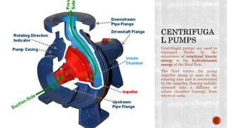
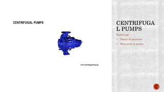
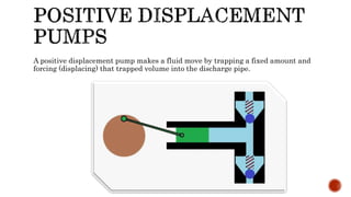
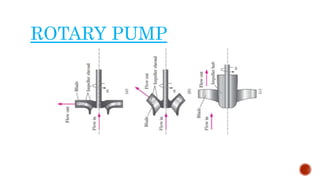
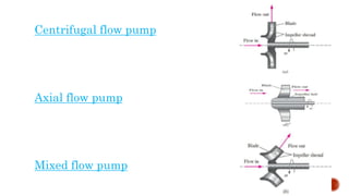
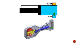
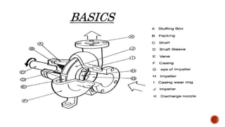
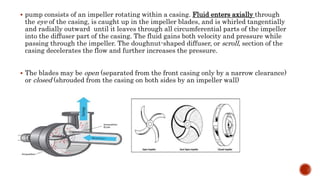
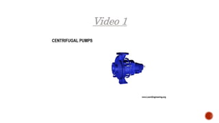
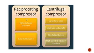
1. Types of rotary pumps like centrifugal and reciprocating pumps, along with their basic operation and characteristics.
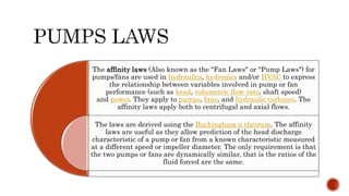
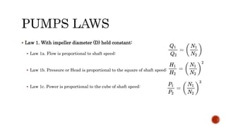
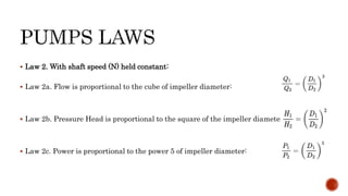
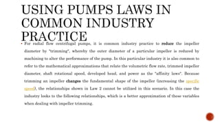
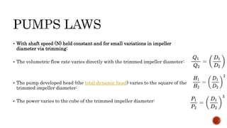
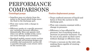
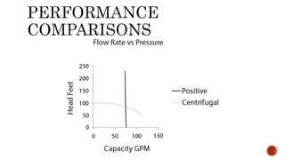
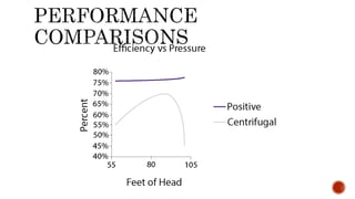
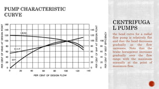
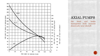
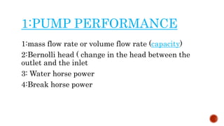
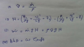
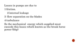
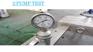
2. Key aspects of pump performance like flow rate, head pressure, horsepower requirements, and efficiency. Affinity laws relating changes in speed and impeller size to performance are also covered.
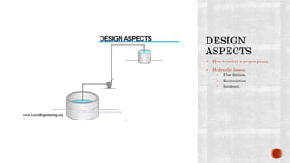
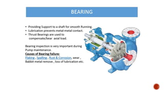
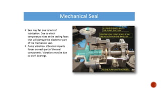
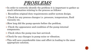
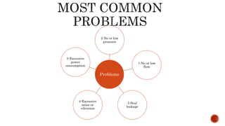
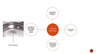
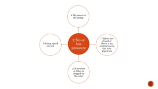
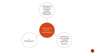
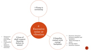
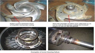
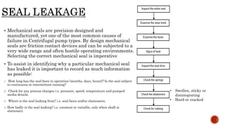
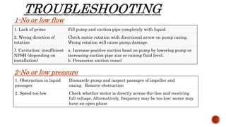
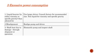
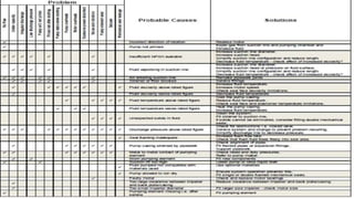
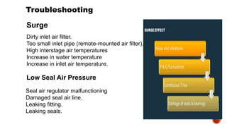
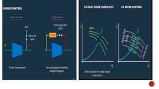
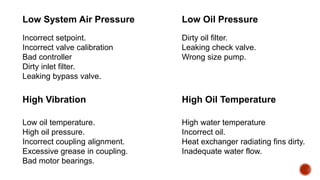
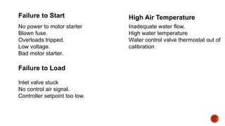
3. Common problems with pumps like low flow, low pressure, excessive power usage, noise, and seal leakage. Potential causes and troubleshooting approaches are provided.
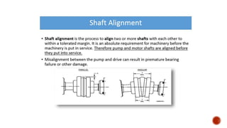
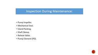
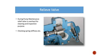
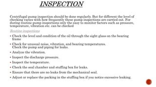
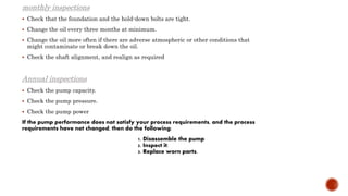
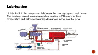
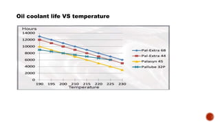
4. Maintenance considerations like inspecting wear parts and monitoring operational parameters are emphasized to prevent problems and improve pump reliability.