Download to read offline

![WORK DONE BY THE CENTRIFUGAL
PUMP ON WATER
• V1 = Absolute velocity of water at inlet
• Vr1 = Relative velocity of water at inlet
• α = Angle made by absolute velocity
• θ = Angle made by relative velocity
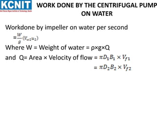
• Work done by the water on the runner per second per unit weight of the water
striking per second is given by equation as
=
• Work done by the impeller on the water per second per unit weight of water
striking per second
= - [ work done in case of turbine]
= -
=
=](https://image.slidesharecdn.com/pptonpump-221222162154-5df6344b/85/PPT-ON-PUMP-pptx-7-320.jpg)
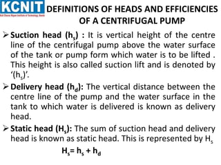


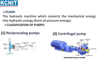
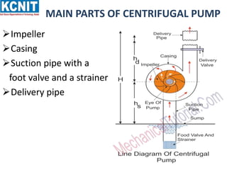
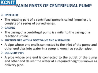
The document provides information about centrifugal pumps. It discusses that a centrifugal pump converts mechanical energy to pressure energy using centrifugal force. It has main parts including an impeller, casing, suction pipe, and delivery pipe. The impeller rotates and increases the tangential velocity of the fluid, raising the pressure and allowing water to be pumped to a higher level. The document defines terms like suction head, delivery head, static head, and manometric head related to the pump's operation. It also provides equations for work done by the impeller on water and efficiency calculations.


