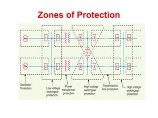
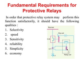
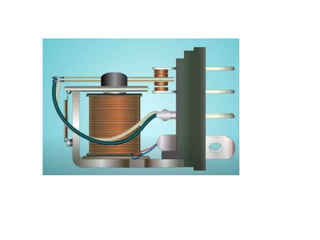
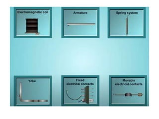
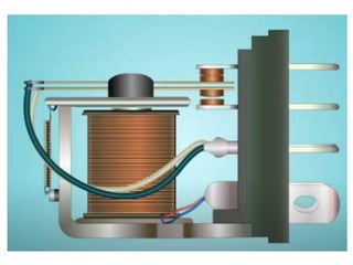
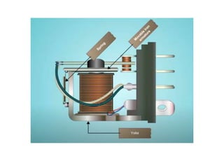
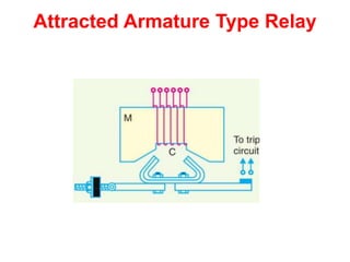
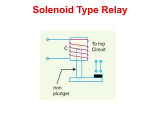
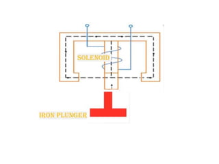
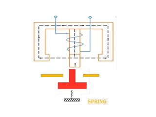
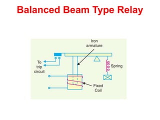
Power System Protection
Chapter-21: Protective Relays
Outlines
• Protective Relay
• Fundamental Requirements for Protective Relays
• Basic Relays
• Relay Timing
• Important Terms
• Time/P.S.M Curve
• Calculation for Relay Operating Timing
• Functional Relay Types
• Types of Protection
Protective Relay
• A protective relay is a device that detects the fault and
initiates the operation of the circuit breaker to isolate
the defective element from the rest of the system.
• The relays detect the abnormal conditions by
measuring the electrical.
• The electrical quantities which may change under
fault conditions are voltage, current, frequency and
phase angle.
Zones of Protection
Fundamental Requirements for
Protective Relays
In order that protective relay system may perform this
function satisfactorily, it should have the following
qualities :
1. Selectivity
2. speed
3. Sensitivity
4. reliability
5. Simplicity
6. economy
Basic Relays
• Most of the relays used following two main operating
principles :
1. Electromagnetic attraction.
2. Electromagnetic induction.
Electromagnetic Attraction
Relays.
• Electromagnetic attraction relays operate by virtue of
an armature being attracted to the poles of an
electromagnet or a plunger being drawn into a
solenoid. There are three types.
1. Attracted armature type relay.
2. Solenoid type relay.
3. Balanced beam type relay.
During interruption (coil is energized)
After interruption (coil is deenergized)
Attracted Armature Type Relay
Solenoid Type Relay
Balanced Beam Type Relay
Induction Relays
• Electromagnetic induction relays operate on the
principle of induction motor.
• They are not used with D.C quantities owing to the
principle of operation.
• An induction relay essentially consists of a pivoted
aluminum disc placed in two alternating magnetic
fields of the same frequency but displaced in time and
space.
Instantaneous Relay
• An instantaneous relay is one in which no intentional
time delay is provided. In this case, the relay contacts
are closed immediately after current in the relay coil
exceeds the minimum calibrated/Pickup value.
Inverse-time Relay
• An inverse-time relay is one in which the operating
time is approximately inversely proportional to the
magnitude of the actuating quantity.
Definite time lag relay
• In this type of relay, there is a definite time elapse
between the instant of pickup and the closing of relay
contacts.
• This particular time setting is independent of the
amount of current through the relay coil.
Important Terms
• Pick-up current:
It is the minimum current in the relay coil at
which the relay starts to operate. So long as the current in the
relay is less than the pick-up value, the relay does not operate and
the breaker controlled by it remains in the closed position.
• Current setting:
It is often desirable to adjust the pick-up current
to any required value. This is known as current setting and is
usually achieved by the use of tapping's on the relay operating
coil.
Current setting (Example)
• For example, suppose that an overcurrent relay having current
setting of 125% is connected to a supply circuit through a
current transformer of 400/5. The rated secondary current of
C.T. is 5A. Therefore, the pick-up value will be 25% more than
5 A
i.e. 5 × 1·25 = 6·25 A.
• It means that with above current setting, the relay will actually
operate for a relay coil current equal to or greater than 6·25 A.
• The current plug settings usually range from 50% to 200% in
steps of 25% for overcurrent relays and 10% to 70% in steps of
10% for earth leakage relays.
• The desired current setting is obtained by inserting a plug
between the jaws of a bridge type socket at the tap value
required.
Conti….
• Plug-setting multiplier (P.S.M.):
It is the ratio of fault current in relay coil to
the pick-up current i.e.
P.S.M. =
Fault current in relay coil
Pick−up current
Time-setting multiplier
• A relay is generally provided with control to
adjust the time of operation. This adjustment
is known as time-setting multiplier. The time-
setting dial is calibrated from 0 to 1 in steps of
0.05 sec
Time/P.S.M Curve
• The horizontal scale is marked in
terms of plug-setting multiplier and
represents the number of times the
relay current is in excess of the
current setting.
• The vertical scale is marked in terms
of the time required for relay
operation. If the P.S.M. is 10, then
the time of operation (from the
curve) is 3 seconds.
• The actual time of operation is
obtained by multiplying this time by
the time-setting multiplier.
Calculation for Relay Operating
Timing
In order to calculate the actual relay operating time, the
following things must be known :
• Time/P.S.M. curve
• Current setting
• Time setting
• Fault current
• CT Ratio
Example
• Determine the time of operation of a 5-ampere, 3-second overcurrent relay
having a current setting of 125% and a time setting multiplier of 0·6
connected to supply circuit through a 400/5 current transformer when the
circuit carries a fault current of 4000 A.
• Solution:
Functional Relay Types
• Induction type overcurrent relays
• Induction type reverse power relays
• Distance relays
• Differential relays
• Translay scheme
Distance Relays
• A group relays in which the operation is governed by the
ratio of applied voltage to current in the protected circuit.
Such relays are called distance or impedance relays.
• In an impedance relay, the torque produced by a current
element is opposed by the torque produced by a voltage
element. The relay will operate when the ratio V/I is less
than a predetermined value.
Distance Relays
Under normal operating conditions, the impedance of the protected zone is ZL .
The relay is so designed that it closes its contacts whenever impedance of the
protected section falls below the pre-determined value i.e. ZL in this case.
Let fault occurs at F1, the impedance where the relay is installed and the point of
fault will be less than ZL and hence the relay operates.
Should the fault occur beyond the protected zone (say point F2), the impedance Z
will be greater than ZL and the relay does not operate
Types of Distance Relays
• Definite-distance relay which operates
instantaneously for fault upto a pre-determined
distance from the relay.
• Time-distance relay in which the time of operation is
proportional to the distance of fault from the relay
point. A fault nearer to the relay will operate it earlier
than a fault farther away from the relay.
• It may be added here that the distance relays are
produced by modifying either of two types of basic
relays; the balance beam or the induction disc.
Differential Relays
• A differential relay is one that operates when the phasor
difference of two or more similar electrical quantities
exceeds a pre-determined value.
• A current differential relay compares the current entering
and leaving the section.
• Under normal operating conditions, the two currents are
equal. When a fault occurs, this condition no longer applies.
The difference between the incoming and outgoing currents
is arranged to flow through the operating coil of the relay.
• If this differential current is equal to or greater than the
pickup value, the relay will operate and open the circuit
breaker to isolate the faulty section
Current Differential Relays
• An overcurrent relay connected to operate as a differential
relay.
• A pair of identical current transformers are fitted on either
end of the section to be protected (alternator winding).
The secondaries of CT’s are connected in series in such a
way that they carry the induced currents in the same
direction.
• The operating coil of the overcurrent relay is connected
across the CT secondary circuit. This differential relay
compares the current at the two ends of the alternator
winding
Current Differential Relays
Conti…
• Under normal operating conditions, suppose the alternator
winding carries a normal current of 1000 A. Then the
currents in the two secondaries of CT’s are equal.
• These currents will merely circulate between the two
CT’s and no current will flow through the differential
relay.
• Therefore, the relay remains inoperative.
• If a ground fault occurs on the alternator winding, then
two secondary currents will not be equal and the current
flows through the operating coil of the relay, causing the
relay to operate.
• The amount of current flow through the relay will depend
upon the way the fault is being fed.
Conti…
• Disadvantages
(i) The impedance of the pilot cables generally causes a slight
difference between the currents at the two ends of the section to
be protected. If the relay is very sensitive, then the small
differential current flowing through the relay may cause it to
operate even under no fault conditions.
(ii) Pilot cable capacitance causes incorrect operation of the relay
when a large through-current flows.
(iii) Accurate matching of current transformers cannot be achieved
due to pilot circuit impedance.
Voltage Balanced Differential Relays
• In this scheme of protection, two similar current transformers are
connected at either end of the element to be protected (e.g. an
alternator winding) by means of pilot wires.
• The secondaries of current transformers are connected in series with
a relay in such a way that under normal conditions, their induced
e.m.f.s’ are in opposition.
• Under healthy conditions, equal currents (I1= I2) flow in both
primary windings.
• Therefore, the secondary voltages of the two transformers are
balanced against each other and no current will flow through the
relay operating coil.
• When a fault occurs, then currents in the two primaries will differ
(i.e. I 1 ≠ I 2 ) and their secondary voltages will no longer be in
balance. This voltage difference will cause a current to flow
through the operating coil of the relay which closes the trip circuit.
Voltage Balanced Differential Relays
Conti…
• Disadvantages
• The voltage balance system suffers from the following
drawbacks :
(i) A multi-gap transformer construction is required to
achieve the accurate balance between current transformer
pairs.
(ii) The system is suitable for protection of cables of
relatively short lengths due to the capacitance of pilot wires.
On long cables, the charging current may be sufficient to
operate the relay even if a perfect balance of current
transformers is attained.
Types of Protection
• Primary Protection:
It is the protection scheme which is
designed to protect the component /parts of the power
system.
Each line has an overcurrent relay that protects the line.
If a fault occurs on any line, it will be cleared by its
relay and circuit breaker. This forms the primary or
main protection and serves as the first line of defence.
Conti….
Conti….
• Back-up protection:
It is the second line of defence in case of
failure of the primary protection. It is designed to
operate with sufficient time delay so that primary
relaying will be given enough time to function if it is
able to.

Protection system Lecture.21 Relays.pptx

  • 1.
  • 2.
    Outlines • Protective Relay •Fundamental Requirements for Protective Relays • Basic Relays • Relay Timing • Important Terms • Time/P.S.M Curve • Calculation for Relay Operating Timing • Functional Relay Types • Types of Protection
  • 3.
    Protective Relay • Aprotective relay is a device that detects the fault and initiates the operation of the circuit breaker to isolate the defective element from the rest of the system. • The relays detect the abnormal conditions by measuring the electrical. • The electrical quantities which may change under fault conditions are voltage, current, frequency and phase angle.
  • 4.
  • 5.
    Fundamental Requirements for ProtectiveRelays In order that protective relay system may perform this function satisfactorily, it should have the following qualities : 1. Selectivity 2. speed 3. Sensitivity 4. reliability 5. Simplicity 6. economy
  • 6.
    Basic Relays • Mostof the relays used following two main operating principles : 1. Electromagnetic attraction. 2. Electromagnetic induction.
  • 7.
    Electromagnetic Attraction Relays. • Electromagneticattraction relays operate by virtue of an armature being attracted to the poles of an electromagnet or a plunger being drawn into a solenoid. There are three types. 1. Attracted armature type relay. 2. Solenoid type relay. 3. Balanced beam type relay.
  • 13.
  • 14.
    After interruption (coilis deenergized)
  • 15.
  • 16.
  • 19.
  • 21.
    Induction Relays • Electromagneticinduction relays operate on the principle of induction motor. • They are not used with D.C quantities owing to the principle of operation. • An induction relay essentially consists of a pivoted aluminum disc placed in two alternating magnetic fields of the same frequency but displaced in time and space.
  • 22.
    Instantaneous Relay • Aninstantaneous relay is one in which no intentional time delay is provided. In this case, the relay contacts are closed immediately after current in the relay coil exceeds the minimum calibrated/Pickup value.
  • 23.
    Inverse-time Relay • Aninverse-time relay is one in which the operating time is approximately inversely proportional to the magnitude of the actuating quantity.
  • 24.
    Definite time lagrelay • In this type of relay, there is a definite time elapse between the instant of pickup and the closing of relay contacts. • This particular time setting is independent of the amount of current through the relay coil.
  • 25.
    Important Terms • Pick-upcurrent: It is the minimum current in the relay coil at which the relay starts to operate. So long as the current in the relay is less than the pick-up value, the relay does not operate and the breaker controlled by it remains in the closed position. • Current setting: It is often desirable to adjust the pick-up current to any required value. This is known as current setting and is usually achieved by the use of tapping's on the relay operating coil.
  • 26.
    Current setting (Example) •For example, suppose that an overcurrent relay having current setting of 125% is connected to a supply circuit through a current transformer of 400/5. The rated secondary current of C.T. is 5A. Therefore, the pick-up value will be 25% more than 5 A i.e. 5 × 1·25 = 6·25 A. • It means that with above current setting, the relay will actually operate for a relay coil current equal to or greater than 6·25 A. • The current plug settings usually range from 50% to 200% in steps of 25% for overcurrent relays and 10% to 70% in steps of 10% for earth leakage relays. • The desired current setting is obtained by inserting a plug between the jaws of a bridge type socket at the tap value required.
  • 27.
    Conti…. • Plug-setting multiplier(P.S.M.): It is the ratio of fault current in relay coil to the pick-up current i.e. P.S.M. = Fault current in relay coil Pick−up current
  • 28.
    Time-setting multiplier • Arelay is generally provided with control to adjust the time of operation. This adjustment is known as time-setting multiplier. The time- setting dial is calibrated from 0 to 1 in steps of 0.05 sec
  • 29.
    Time/P.S.M Curve • Thehorizontal scale is marked in terms of plug-setting multiplier and represents the number of times the relay current is in excess of the current setting. • The vertical scale is marked in terms of the time required for relay operation. If the P.S.M. is 10, then the time of operation (from the curve) is 3 seconds. • The actual time of operation is obtained by multiplying this time by the time-setting multiplier.
  • 30.
    Calculation for RelayOperating Timing In order to calculate the actual relay operating time, the following things must be known : • Time/P.S.M. curve • Current setting • Time setting • Fault current • CT Ratio
  • 31.
    Example • Determine thetime of operation of a 5-ampere, 3-second overcurrent relay having a current setting of 125% and a time setting multiplier of 0·6 connected to supply circuit through a 400/5 current transformer when the circuit carries a fault current of 4000 A. • Solution:
  • 32.
    Functional Relay Types •Induction type overcurrent relays • Induction type reverse power relays • Distance relays • Differential relays • Translay scheme
  • 33.
    Distance Relays • Agroup relays in which the operation is governed by the ratio of applied voltage to current in the protected circuit. Such relays are called distance or impedance relays. • In an impedance relay, the torque produced by a current element is opposed by the torque produced by a voltage element. The relay will operate when the ratio V/I is less than a predetermined value.
  • 34.
    Distance Relays Under normaloperating conditions, the impedance of the protected zone is ZL . The relay is so designed that it closes its contacts whenever impedance of the protected section falls below the pre-determined value i.e. ZL in this case. Let fault occurs at F1, the impedance where the relay is installed and the point of fault will be less than ZL and hence the relay operates. Should the fault occur beyond the protected zone (say point F2), the impedance Z will be greater than ZL and the relay does not operate
  • 35.
    Types of DistanceRelays • Definite-distance relay which operates instantaneously for fault upto a pre-determined distance from the relay. • Time-distance relay in which the time of operation is proportional to the distance of fault from the relay point. A fault nearer to the relay will operate it earlier than a fault farther away from the relay. • It may be added here that the distance relays are produced by modifying either of two types of basic relays; the balance beam or the induction disc.
  • 36.
    Differential Relays • Adifferential relay is one that operates when the phasor difference of two or more similar electrical quantities exceeds a pre-determined value. • A current differential relay compares the current entering and leaving the section. • Under normal operating conditions, the two currents are equal. When a fault occurs, this condition no longer applies. The difference between the incoming and outgoing currents is arranged to flow through the operating coil of the relay. • If this differential current is equal to or greater than the pickup value, the relay will operate and open the circuit breaker to isolate the faulty section
  • 37.
    Current Differential Relays •An overcurrent relay connected to operate as a differential relay. • A pair of identical current transformers are fitted on either end of the section to be protected (alternator winding). The secondaries of CT’s are connected in series in such a way that they carry the induced currents in the same direction. • The operating coil of the overcurrent relay is connected across the CT secondary circuit. This differential relay compares the current at the two ends of the alternator winding
  • 38.
  • 39.
    Conti… • Under normaloperating conditions, suppose the alternator winding carries a normal current of 1000 A. Then the currents in the two secondaries of CT’s are equal. • These currents will merely circulate between the two CT’s and no current will flow through the differential relay. • Therefore, the relay remains inoperative. • If a ground fault occurs on the alternator winding, then two secondary currents will not be equal and the current flows through the operating coil of the relay, causing the relay to operate. • The amount of current flow through the relay will depend upon the way the fault is being fed.
  • 40.
    Conti… • Disadvantages (i) Theimpedance of the pilot cables generally causes a slight difference between the currents at the two ends of the section to be protected. If the relay is very sensitive, then the small differential current flowing through the relay may cause it to operate even under no fault conditions. (ii) Pilot cable capacitance causes incorrect operation of the relay when a large through-current flows. (iii) Accurate matching of current transformers cannot be achieved due to pilot circuit impedance.
  • 41.
    Voltage Balanced DifferentialRelays • In this scheme of protection, two similar current transformers are connected at either end of the element to be protected (e.g. an alternator winding) by means of pilot wires. • The secondaries of current transformers are connected in series with a relay in such a way that under normal conditions, their induced e.m.f.s’ are in opposition. • Under healthy conditions, equal currents (I1= I2) flow in both primary windings. • Therefore, the secondary voltages of the two transformers are balanced against each other and no current will flow through the relay operating coil. • When a fault occurs, then currents in the two primaries will differ (i.e. I 1 ≠ I 2 ) and their secondary voltages will no longer be in balance. This voltage difference will cause a current to flow through the operating coil of the relay which closes the trip circuit.
  • 42.
  • 43.
    Conti… • Disadvantages • Thevoltage balance system suffers from the following drawbacks : (i) A multi-gap transformer construction is required to achieve the accurate balance between current transformer pairs. (ii) The system is suitable for protection of cables of relatively short lengths due to the capacitance of pilot wires. On long cables, the charging current may be sufficient to operate the relay even if a perfect balance of current transformers is attained.
  • 44.
    Types of Protection •Primary Protection: It is the protection scheme which is designed to protect the component /parts of the power system. Each line has an overcurrent relay that protects the line. If a fault occurs on any line, it will be cleared by its relay and circuit breaker. This forms the primary or main protection and serves as the first line of defence.
  • 45.
  • 46.
    Conti…. • Back-up protection: Itis the second line of defence in case of failure of the primary protection. It is designed to operate with sufficient time delay so that primary relaying will be given enough time to function if it is able to.

Editor's Notes

  • #44 The above disadvantages overcome in Translay balanced voltage system.