Electromagnetic relay
• Definition:Electromagnetic relays are those
relay which operates on the principle of
electromagnetic attraction.
• It is a type of a magnetic switch which uses
the magnet for creating a magnetic field.
• The magnetic field then uses for opening and
closing the switch and for performing the
mechanical operation.
4.
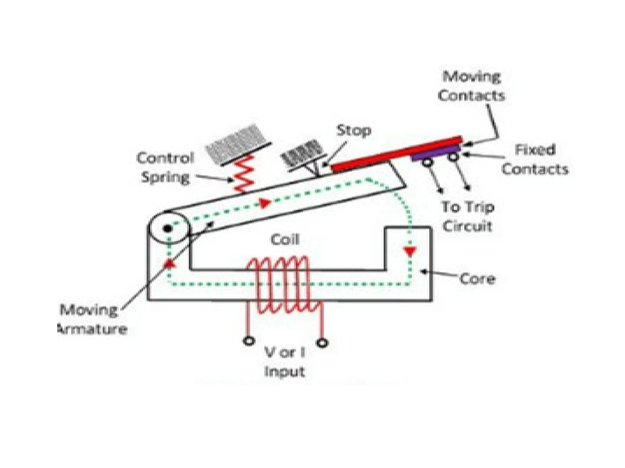
• When thecontrol circuit is energized, the
electromagnet generates a magnetic field.
• The magnetic field pulls the switch to the
closed position, completing the circuit.
• When the current to the coil is switched off,
the armature is returned to its relaxed
position by a force that is half as strong as the
magnetic force
• This is usually done by spring.
5.
ADVANTAGES OF ELECTROMAGNETICRELAY
• Can be used for DC and AC.
• They have fast operation and fast reset .
• High operating speed with operating time.
• The pickup can be as high as 90-95% for dc
operation and 60-90% for ac.
6.
Disadvantages
• Due tomoving parts ,the response is not very
quick due to the parts as compared to static
relay.
• Life is less
• High failure rate compared to static relay.
7.
APPLICATION
• The protectionfor various ac and dc
equipment.
• Over/under current and voltage protection of
various Ac and Dc equipments.
• In the earth fault protection relay.
• For the differential protection.
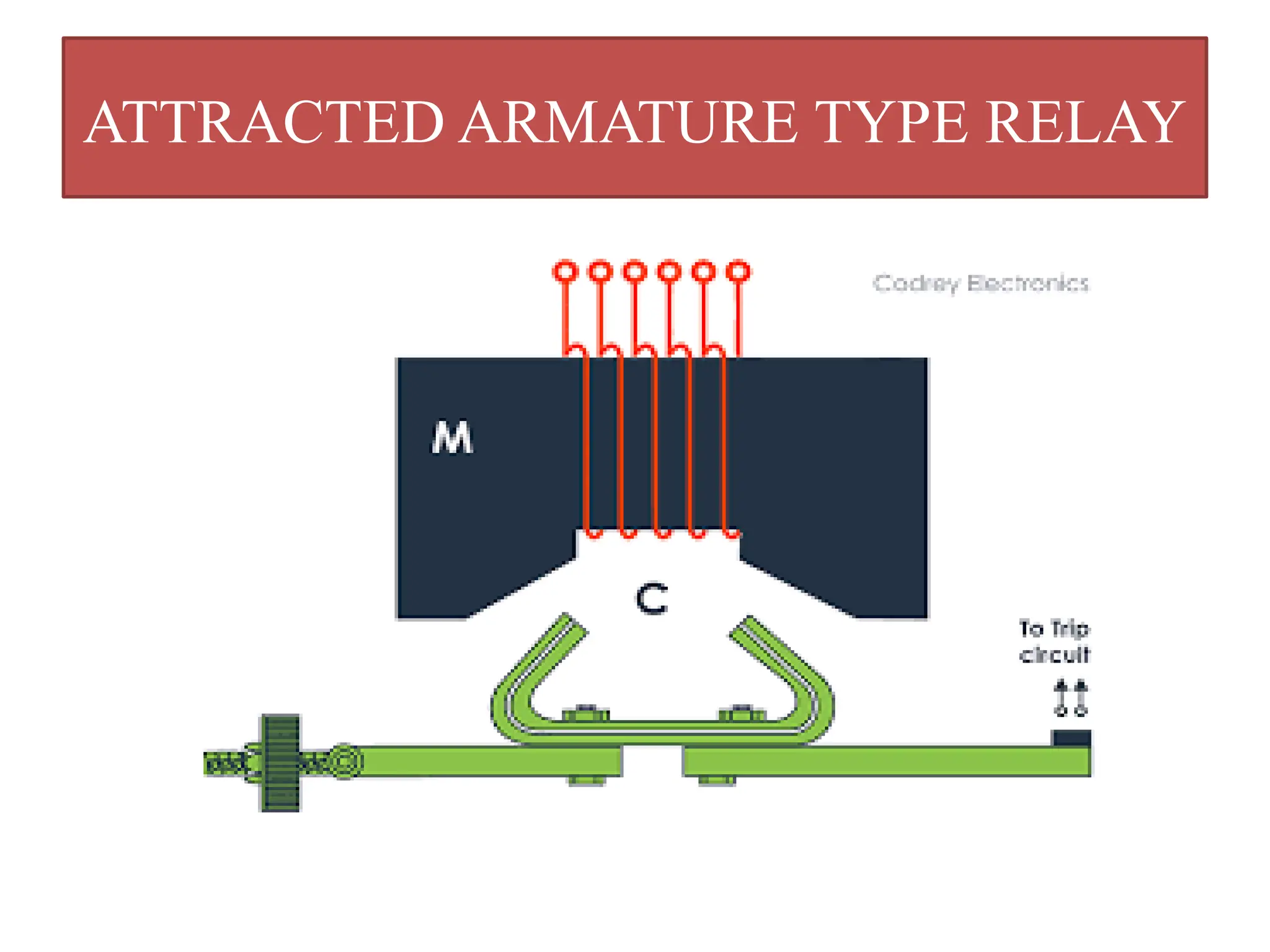
Construction
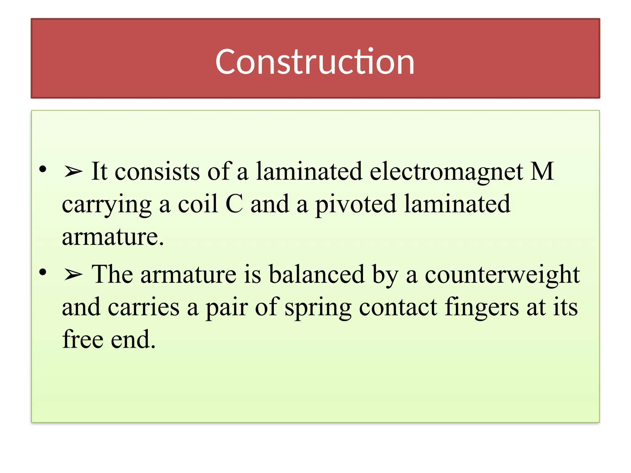
• ➢ Itconsists of a laminated electromagnet M
carrying a coil C and a pivoted laminated
armature.
• ➢ The armature is balanced by a counterweight
and carries a pair of spring contact fingers at its
free end.
11.
Working
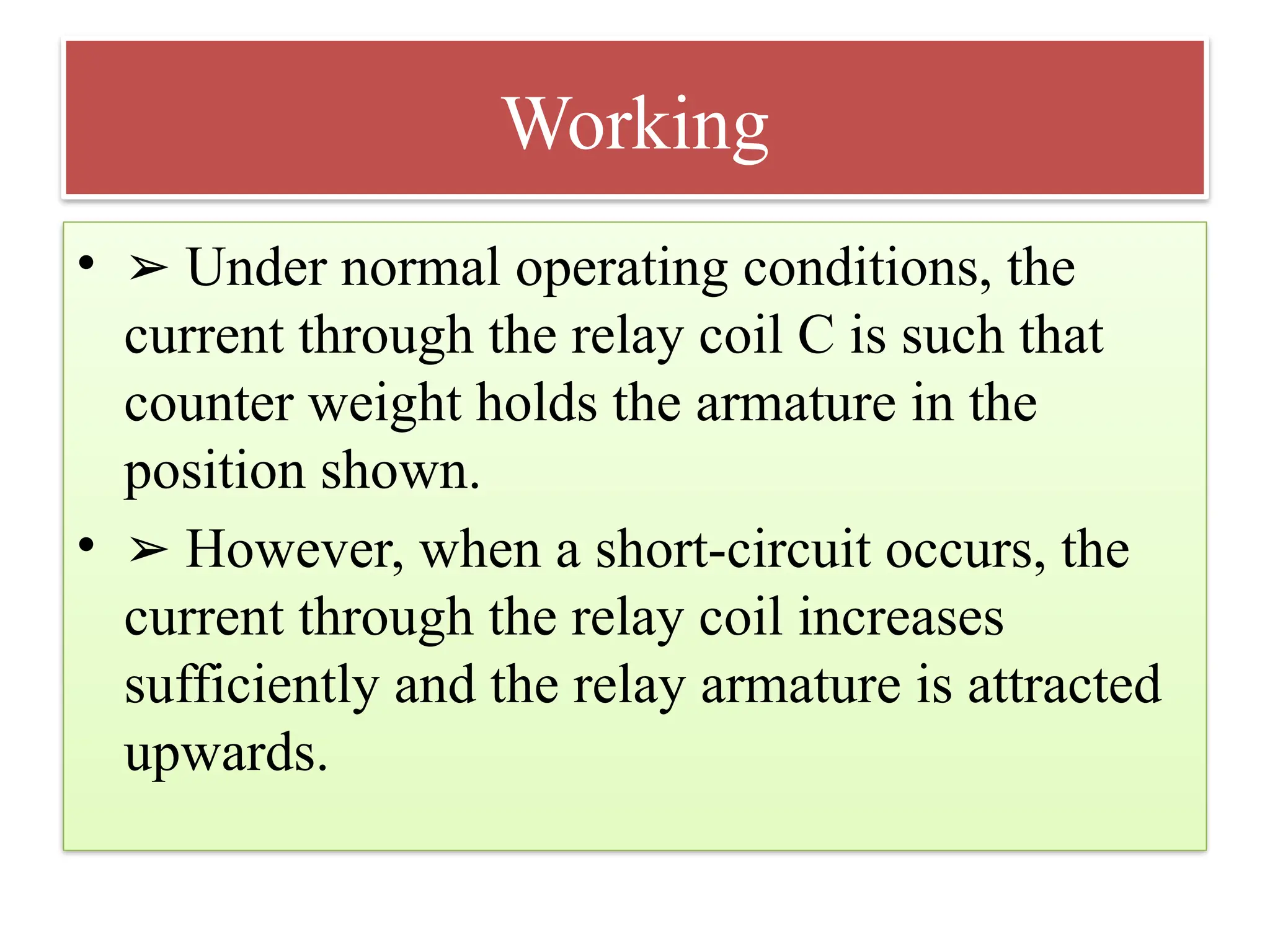
• ➢ Undernormal operating conditions, the
current through the relay coil C is such that
counter weight holds the armature in the
position shown.
• ➢ However, when a short-circuit occurs, the
current through the relay coil increases
sufficiently and the relay armature is attracted
upwards.
12.
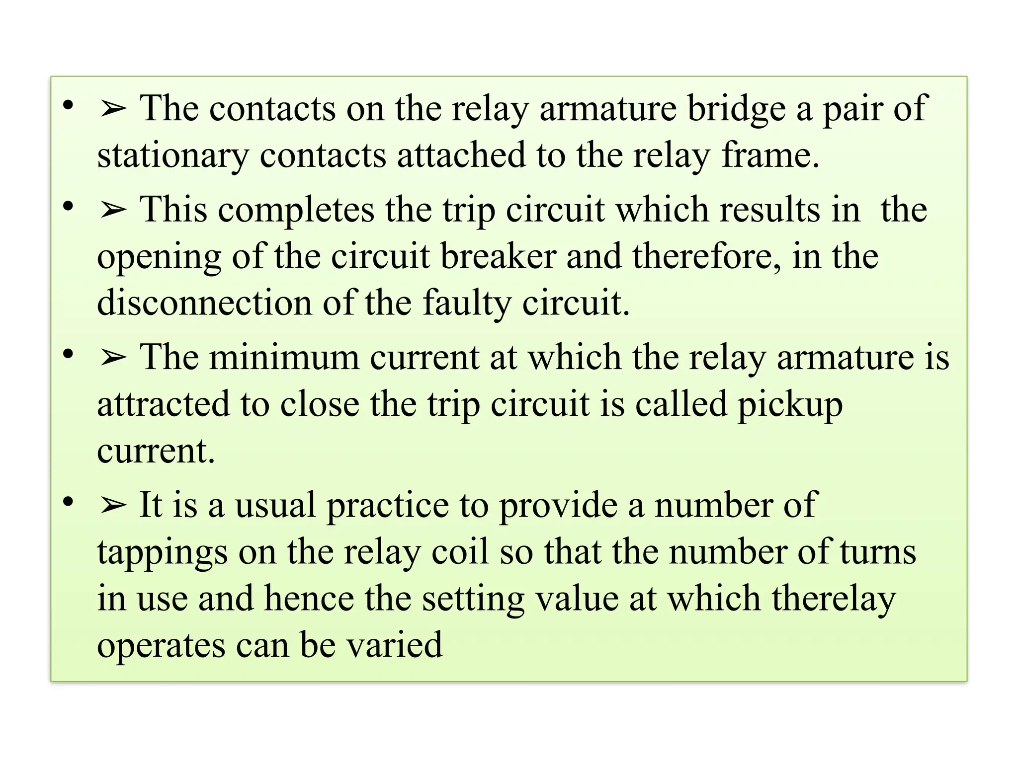
• ➢ Thecontacts on the relay armature bridge a pair of
stationary contacts attached to the relay frame.
• ➢ This completes the trip circuit which results in the
opening of the circuit breaker and therefore, in the
disconnection of the faulty circuit.
• ➢ The minimum current at which the relay armature is
attracted to close the trip circuit is called pickup
current.
• ➢ It is a usual practice to provide a number of
tappings on the relay coil so that the number of turns
in use and hence the setting value at which therelay
operates can be varied
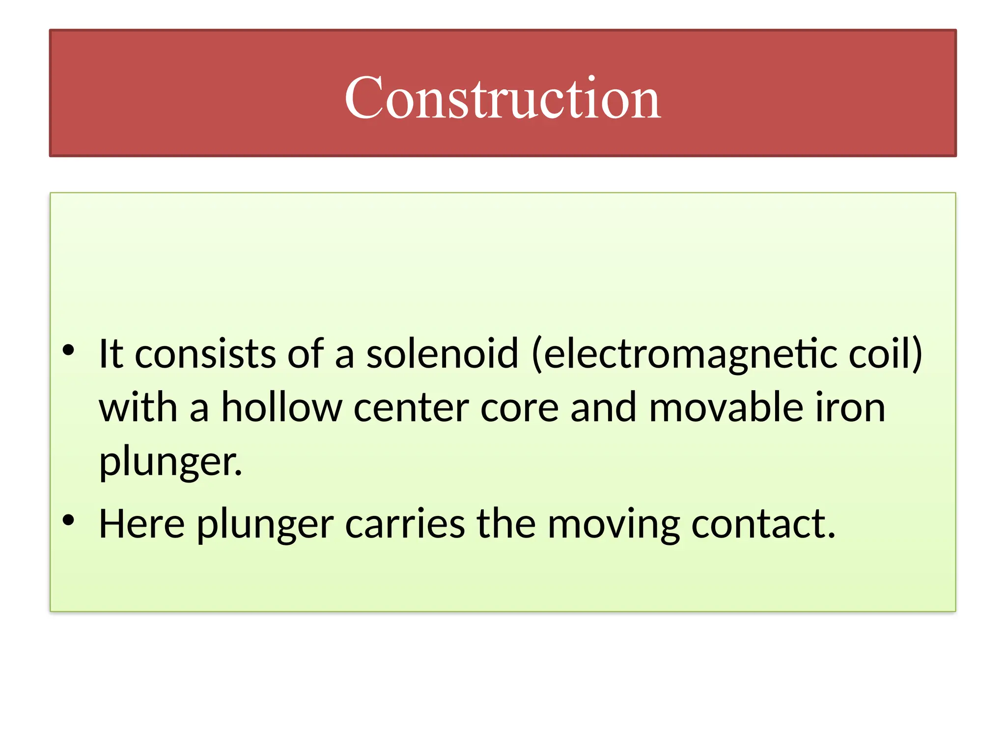
Construction
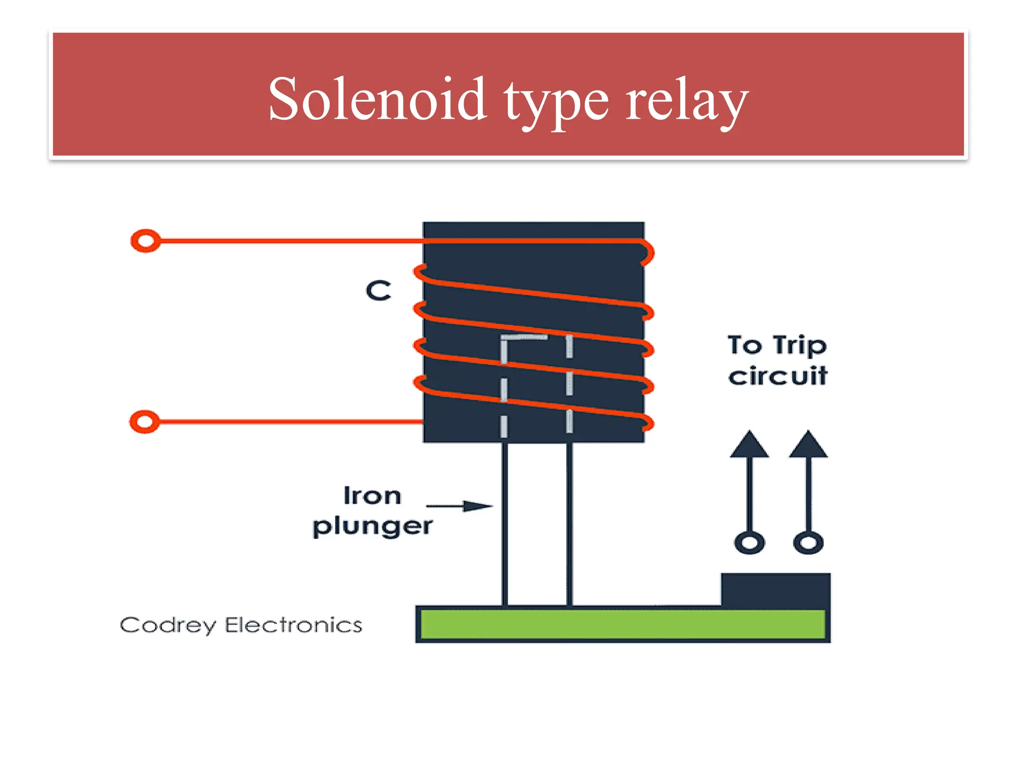
• It consistsof a solenoid (electromagnetic coil)
with a hollow center core and movable iron
plunger.
• Here plunger carries the moving contact.
15.
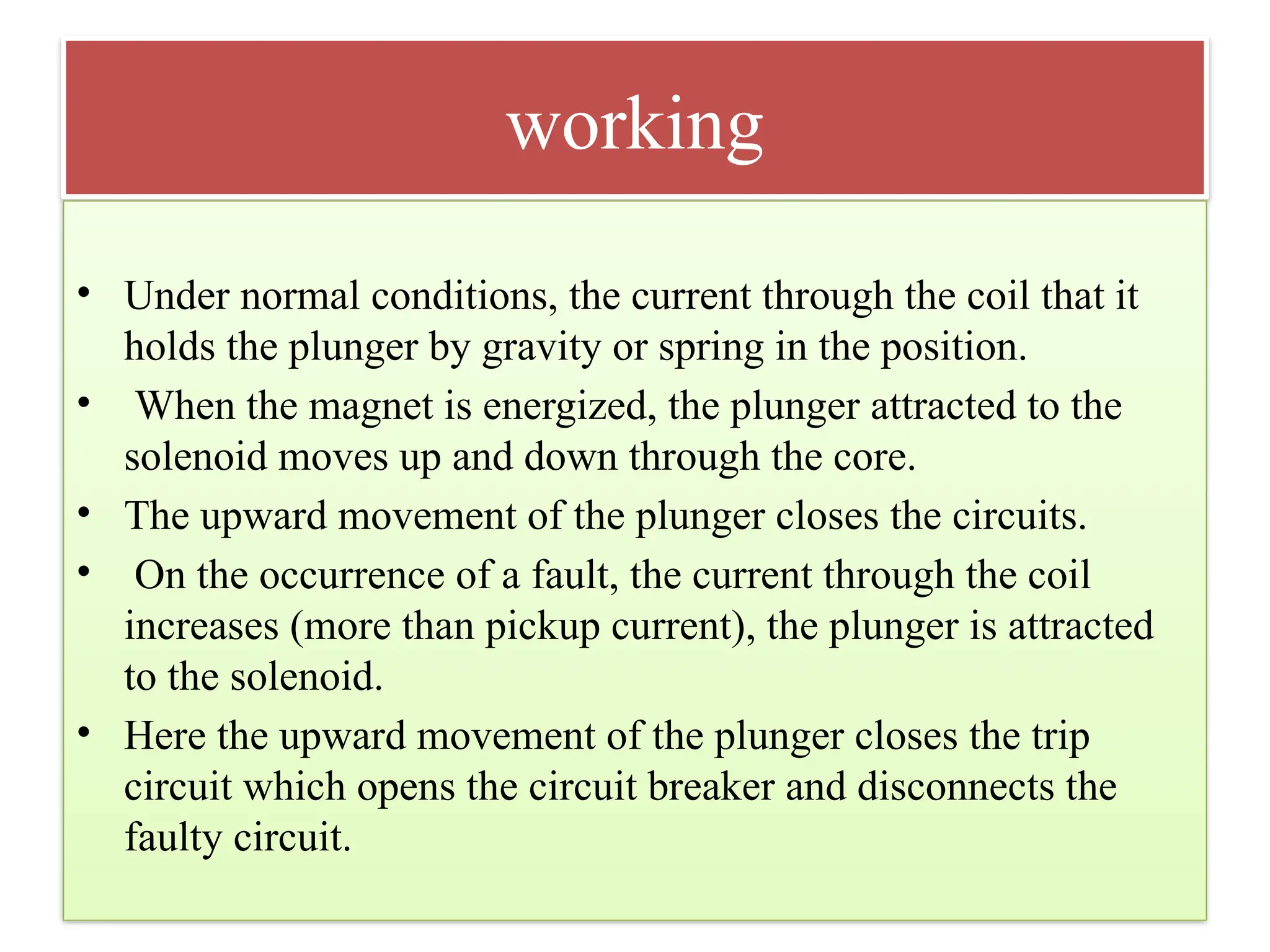
working
• Under normalconditions, the current through the coil that it
holds the plunger by gravity or spring in the position.
• When the magnet is energized, the plunger attracted to the
solenoid moves up and down through the core.
• The upward movement of the plunger closes the circuits.
• On the occurrence of a fault, the current through the coil
increases (more than pickup current), the plunger is attracted
to the solenoid.
• Here the upward movement of the plunger closes the trip
circuit which opens the circuit breaker and disconnects the
faulty circuit.
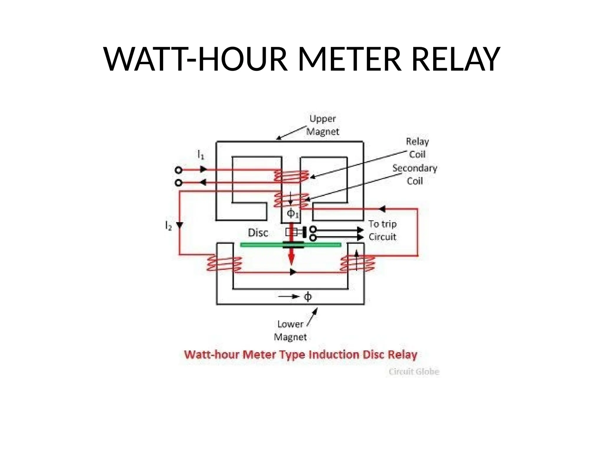
CONSTRUCTION
• It hastwo electromagnets, a series magnet and a shunt
magnet, both are excited from a single source and a
aluminum Spiral disc which freely rotate between them.
• The upper magnet is E shaped and the lower magnet is U
shaped.
• On the middle limb of the upper electromagnet, there are
two windings primary winding and secondary windings.
• The primary current is carrying the relay current I1, while
the secondary winding is connected to the windings of
the U-shaped electromagnet.
19.
working
• When theprimary is connected to the ac supply, it carries alternating current I1, which produces
the flux Φ1.
• Φ1 = Φ1max sin( wt)
• This Φ1 flux links with secondary and induces emf in it.
• The emf circulates current I2 in the secondary,
• I2 produces flux Φ2..
• Φ2 = Φ2max sin(wt + α)
• The fluxes Φ1 and Φ2have phase difference of α between them
• Both Φ1 and Φ2 are alternating fluxes which link with the disc.
• These flux link with the disc and produce eddy currents.
• The eddy current produce their own flux.
• The eddy current flux and Φ1 Φ2 interact and produce resultant torque on the disc.
• T
• The disc rotate and relay contacts are closed due to which trip signal is send to circuit breaker.
• The circuit breaker breaks the circuit and disconnect the faulty part of the system.
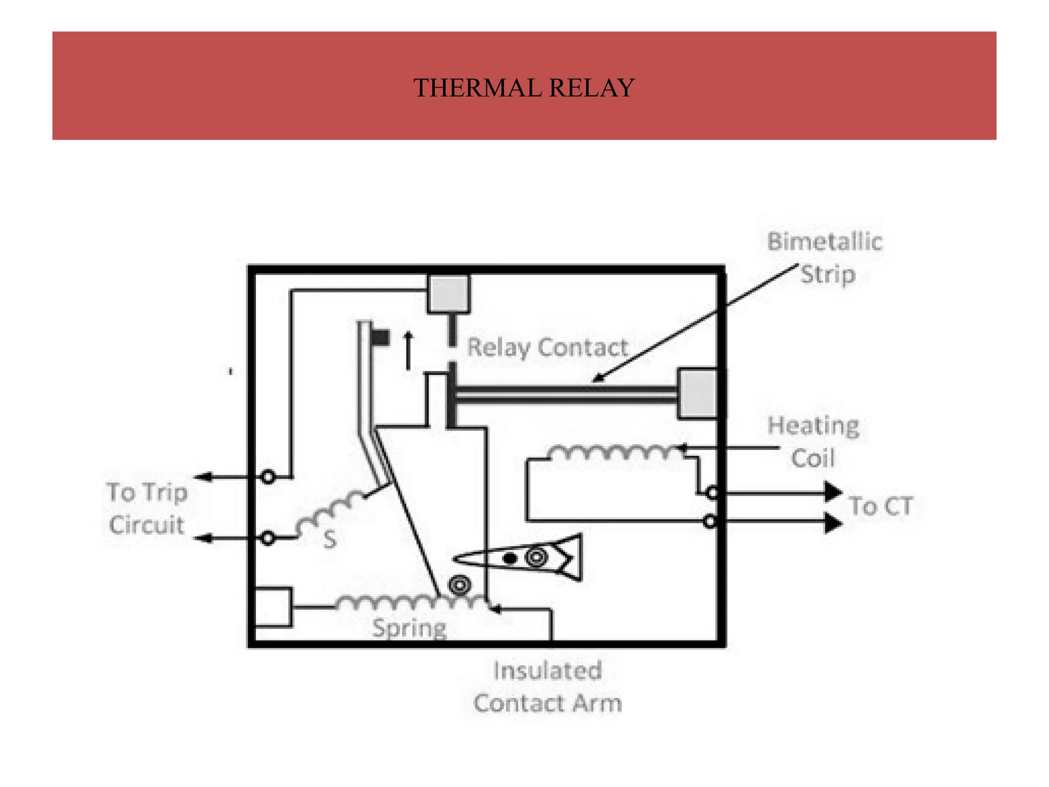
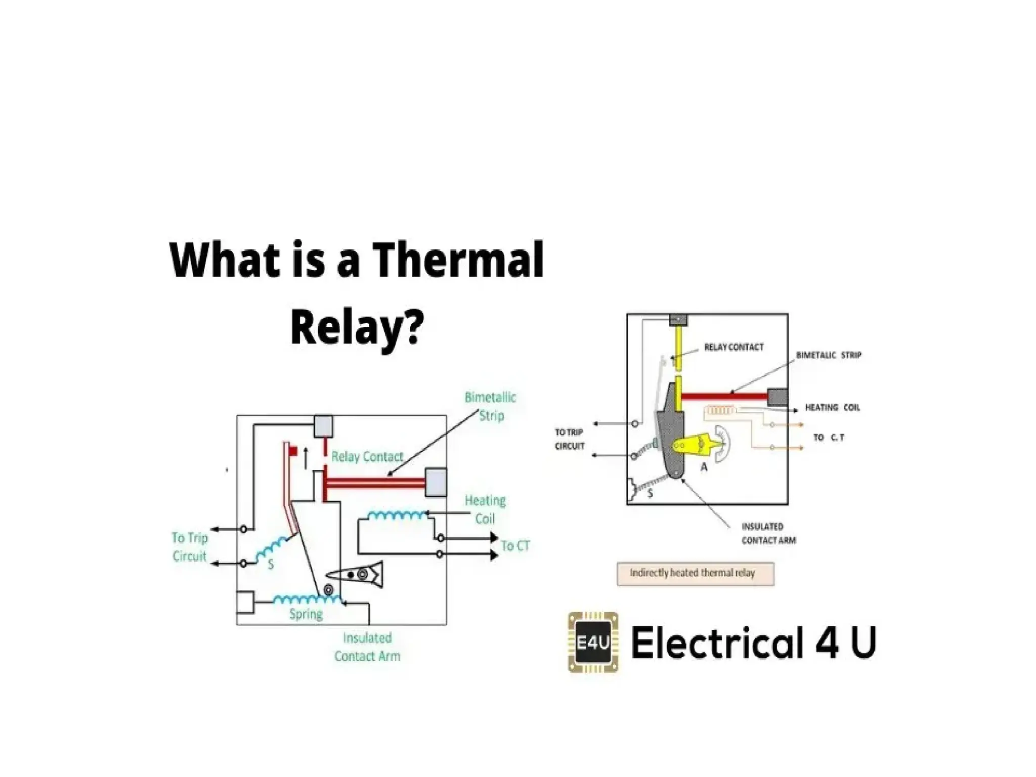
Construction
• It consistof bimetallic strips these strips are
made using different materials like steel & the
alloy of nickel.
• CT is connected with the heating coil.
• The insulated liver arm is connected to the trip
coil along with the spring and the bimetallic
strips. The tension of the spring is varied by
the help of the sector-shaped plate.
23.
Working
• Works onthe principle of thermal effect of electric current.
• The bimetallic strip is heated by heating coil, supplied through
the CT.
• Under normal working condition, the bimetallic strip are
straight .
• Under abnormal condition, high current flows from the CT to the
heating coil, heating coil radiates its heat towards the bimetallic
strip, the bimetallic strip bends, the tension of the spring is
released, thus the relay contact are closed which energizes the trip
circuit.
24.
ADVANTAGE
• Thermal relayshave greater accuracy.
• They protect electrical motors from overheating eventually. So
they can be used conveniently in 1phase & 3 phase motors.
• These relays are installed easily.
• These relays are available with automatic & manual reset
functions for simple operations.
• These are very active on a wide & adjustable range of current.
• They have a trip-free mechanism used for optimal operation.
• They include temperature compensation features used for
precise functioning.
• These can be used readily anywhere.
25.
Disadvantage
• Thermal relaysdo not come with short circuit protection although they offer electrical
protection. A thermal relay is not used for short circuit protection because it is designed to
respond slowly to excessive current over a period of time, whereas a short circuit generates a
very high current almost instantaneously, which a thermal relay cannot react to quickly enough
to provide effective protection; therefore, dedicated devices like fuses or circuit breakers are
needed for short circuit protection.
• Such type of relay is not used under short-circuit condition. The short circuit current increases
the temperature of the bimetallic strips due to which the contacts of the relay close very fast.
• The thermal relay is used with the short circuit relay or with the time limit fuse.
• Most thermal relay-based devices’ operation is slow.
• These are not designed by direct breaking functions but they need to be utilized with other
electrical protection & switching devices for detaching a live circuit.
• They optimally work against low-resistance circuits(Low resistance means that more current
flows).
• When they are used in heavy-duty circuits then they do not perform well always.
• These are not able to withstand vibrations and electrical shocks.
• These relays do not available with a high switching frequency.
26.
Application
• Used inoverload protection of the motor.
• Mainly used in the low voltage Squirrel Cage induction motor and in low output rating DC
motor. The thermal relay has low overloading capability. It is designed to operate under 6 to 7
times more than the full load current.
• This is a protective device mainly designed to cut the power once the electric motor utilizes
extra current for an extended period of time.
• These relays are helpful in protecting electrical devices, motors & transformers from
overheating.
• These are protective electrical appliances mainly used for overload protection of electrical
circuits and devices.
• This is used mainly in low-output rating DC motors & low voltage-based squirrel cage induction
motors.
• These relays are utilized in motor starter circuits to avoid the motor from using extreme current
that is very dangerous to the insulation of the motor.
• These relays avoid motor damage & also keep the equipment working for a very long time.
• This relay is used in a DC motor with a low output rating & squirrel cage induction motor with
low voltage.
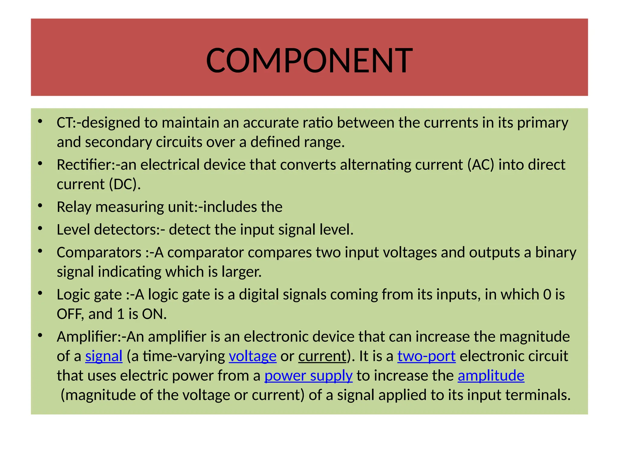
COMPONENT
• CT:-designed tomaintain an accurate ratio between the currents in its primary
and secondary circuits over a defined range.
• Rectifier:-an electrical device that converts alternating current (AC) into direct
current (DC).
• Relay measuring unit:-includes the
• Level detectors:- detect the input signal level.
• Comparators :-A comparator compares two input voltages and outputs a binary
signal indicating which is larger.
• Logic gate :-A logic gate is a digital signals coming from its inputs, in which 0 is
OFF, and 1 is ON.
• Amplifier:-An amplifier is an electronic device that can increase the magnitude
of a signal (a time-varying voltage or current). It is a two-port electronic circuit
that uses electric power from a power supply to increase the amplitude
(magnitude of the voltage or current) of a signal applied to its input terminals.
29.
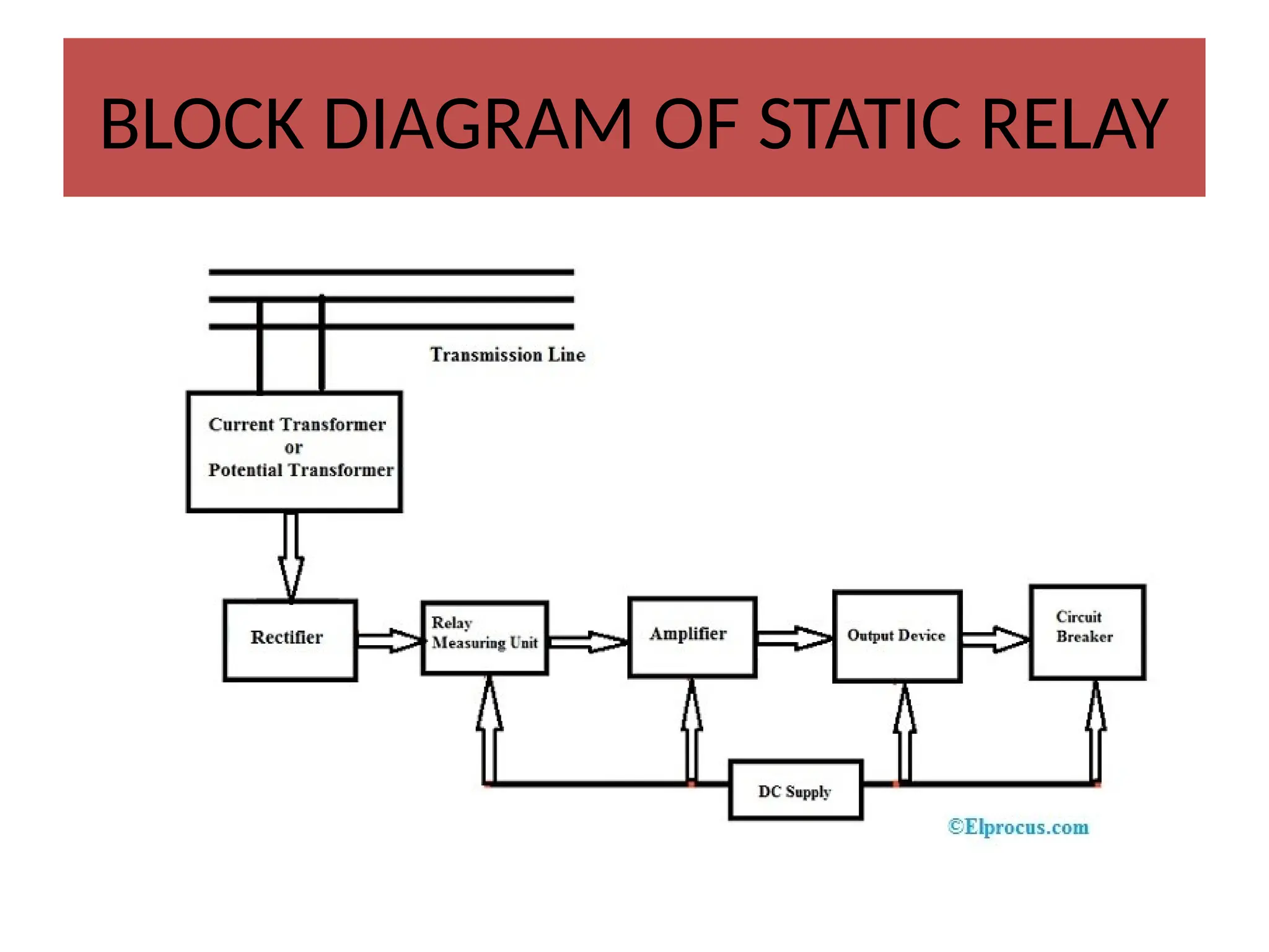
Working
• The outputof the current transformer is given as an input to the rectifier
which rectifies the input AC signal into the DC signal. This DC signal is
given to the measuring unit of a relay.
• In measuring unit, relay detect the input signal level by the level detectors
and evaluates the magnitude & phase of the signal with input signal by the
amplitude comparators and phase comparators to perform the logic gate
operations.
• The main function of the amplitude comparator is to compare the input
signal’s magnitude whereas the phase comparator is used to compare the
phase variation of the input quantity.
• The relay measuring unit o/p is given to the amplifier so that it amplifies
the signal’s magnitude & transmits it to the o/p device.
• So this device will give signal to the trip coil so that it trips the CB (circuit
breaker).
30.
Advantages
• These relaysconsume very less power.
• This relay gives very quick response, high reliability, accuracy, and long
life & it is shockproof.
• This type of relay amplifies the i/p signal which enhances their
sensitivity.
• The unwanted tripping chance is less.
• It needs less maintenance.
• It has a very quick response time.
• These types of relays give resistance to shock & vibrations.
• It has a very quick resetting time.
• It operates for an extremely long period
• It consumes very less power & draws power from a secondary dc supply
31.
Disadvantage
• For theoperation of the amplifier, the
measuring unit of the relay & the o/p device
requires an extra DC supply. So this is the main
drawback of this static relay.
32.
Overcurrent Relay
• Theovercurrent relay is defined as the relay,
which operates only when the value of the
current is greater than the relay setting time. It
protects the equipment of the power system
from the fault current.
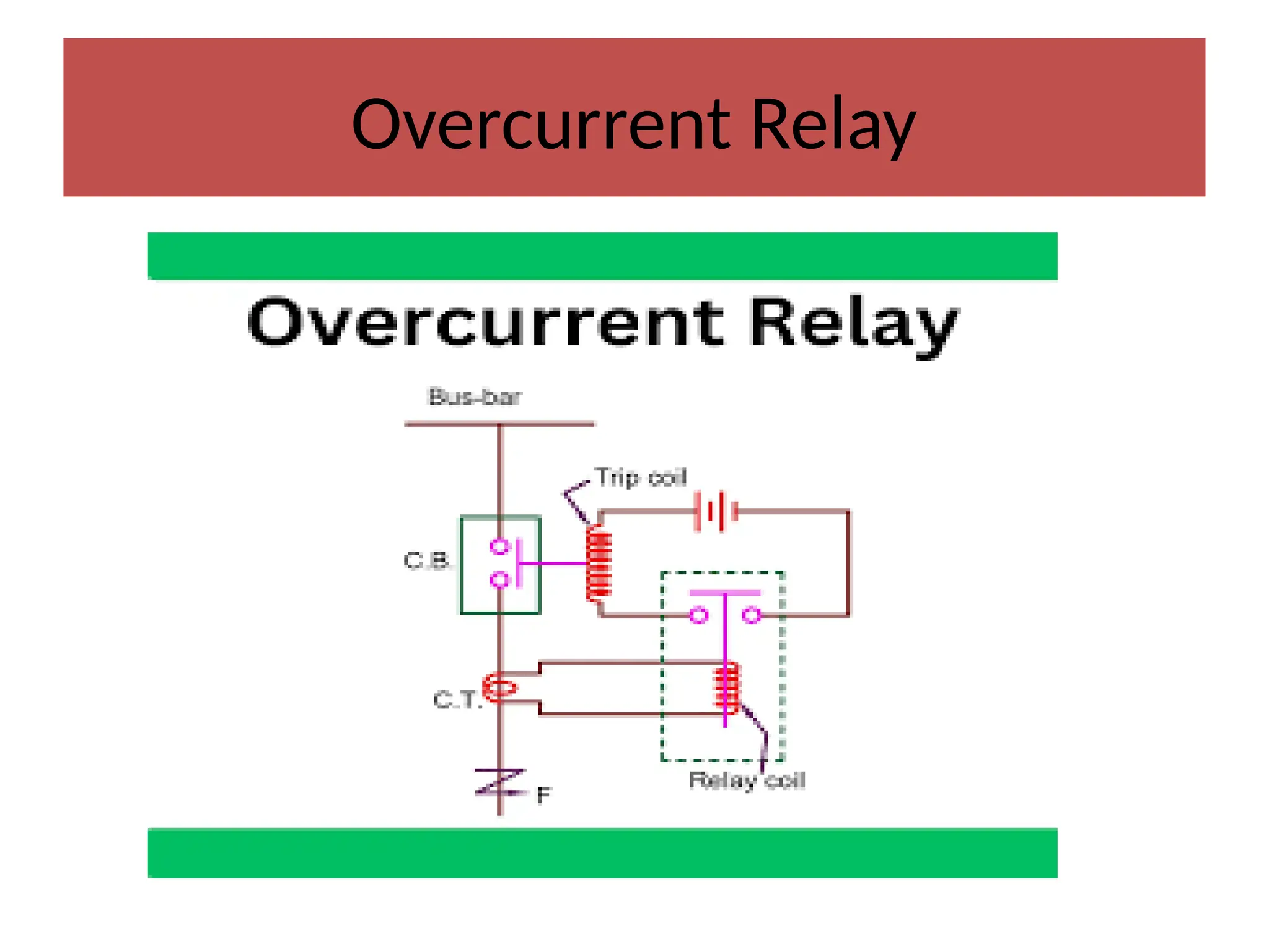
Working
• Under normalworking conditions, the current through the CT which
goes into the relay coil is such that the magnetic field produced by
the coil isn’t enough to attract the handle which goes through the
relay coil. The handle is restrained by a control spring whose force is
higher than the attraction force of the relay coil electromagnet.
• As soon as the current in the main bus bar rises beyond the set
threshold, the current transformer sends a higher current to the
relay coil. This current causes the relay coil to energize highly enough
to attract the handle.
• As it is clear from the image above, the handle causes the circuit of
the trip coil to complete which is connected to a battery. The trip coil
thus breaks the circuit and avoids any overcurrent situation.
35.
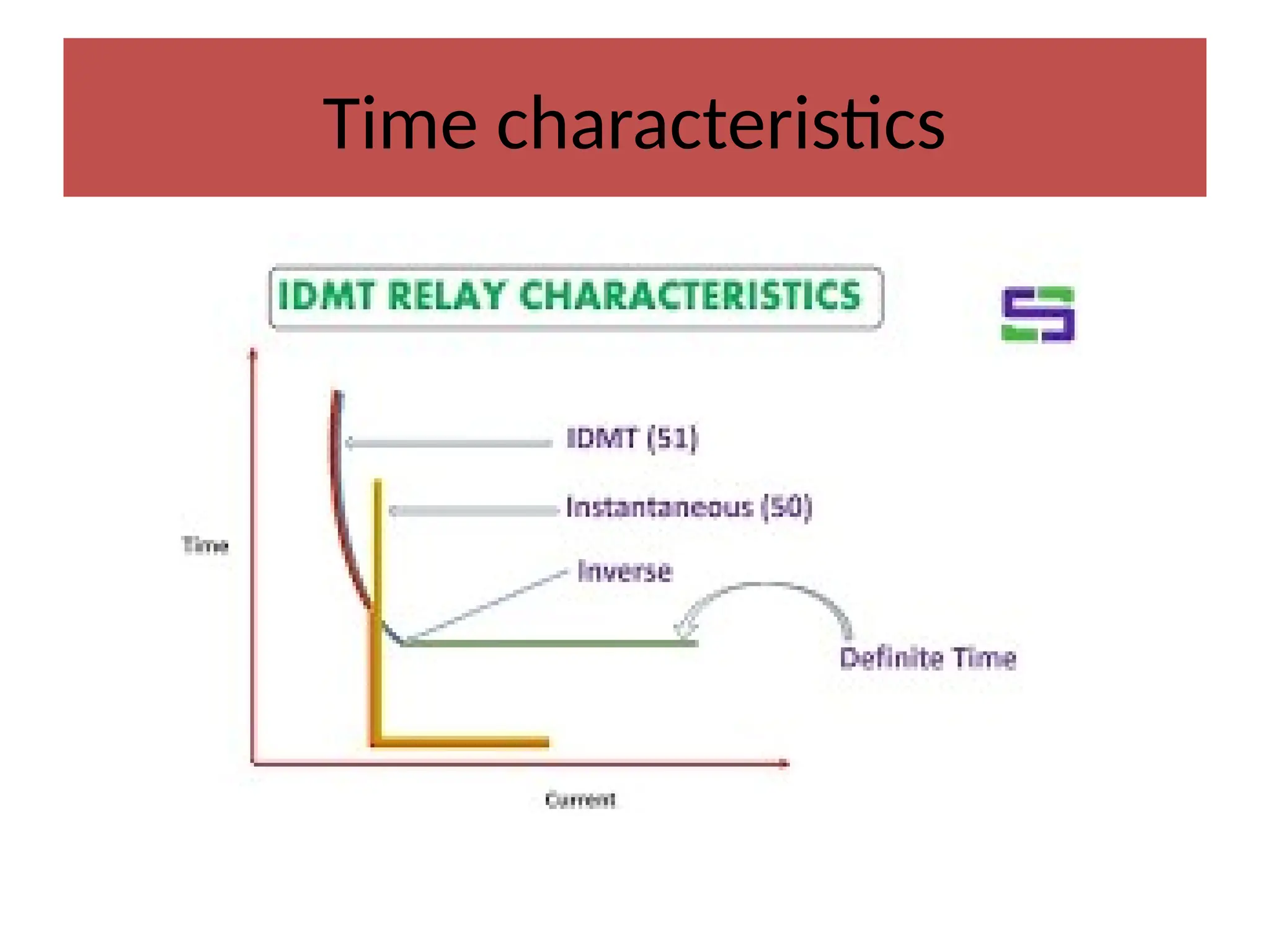
Time- Current characteristicsof
OVERCURRENT RELAY
The time current characteristics of overcurrent relay
are based on the time it takes for the relay to operate,
which is shown by a curve based time and the current.
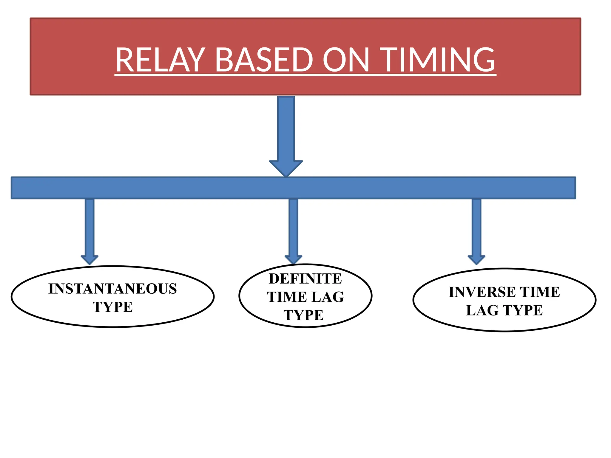
Instantaneous Overcurrent Relay
This relay type is designed to protect against very high
currents(short circuit current) for a short time (less
than 0.1 seconds).
This relay has a low delay time, which means it will trip
the circuit or open it as soon as current is detected.
36.
Instantaneous Overcurrent Relay
•The relay has no intentional time delay for
operation.
• The contacts of the relay are closed instantly
when the current inside the relay rises beyond
the operational value.
• The time interval between the instant pick-up
value and the closing contacts of the relay is very
less.
37.
• Inverse TimeOvercurrent Relay
• The operating time of the inverse-time
overcurrent relay is inversely proportional,
unlike the instantaneous type.
• This means that a higher current will
decrease the time required for the relay's
operation,
• whereas a lower current will increase the time
needed, up to 10 seconds. This is important to
prevent false trips if there is surge of current
used in distribution systems.
38.
Inverse-Time Overcurrent Relay
•The relay operates only when the magnitude
of their operating current is inversely
proportional to the magnitude of the energize
quantities. The operating time of relay
decreases with the increases in the current.
The operation of the relay depends on the
magnitude of the
39.
• Definite TimeDelay Overcurrent Relay
• It is relay type is similar to an inverse time-delay overcurrent
relay in that it will only trip or open the circuit if the current
exceeds a specific level for a specified amount of time.
• The definite time-delay overcurrent relay, however, has a set or
fixed time delay.
• The relay will always trip or open the circuit in the same
amount of time, no matter how much current is flowing. This
is usually set by the user.
• These types of overcurrent relays operate regardless of the
current amount as long as it is above a predetermined value.
• They can be used for applications like transmission lines or
transformers, where the trip must occur after a certain time
delay.
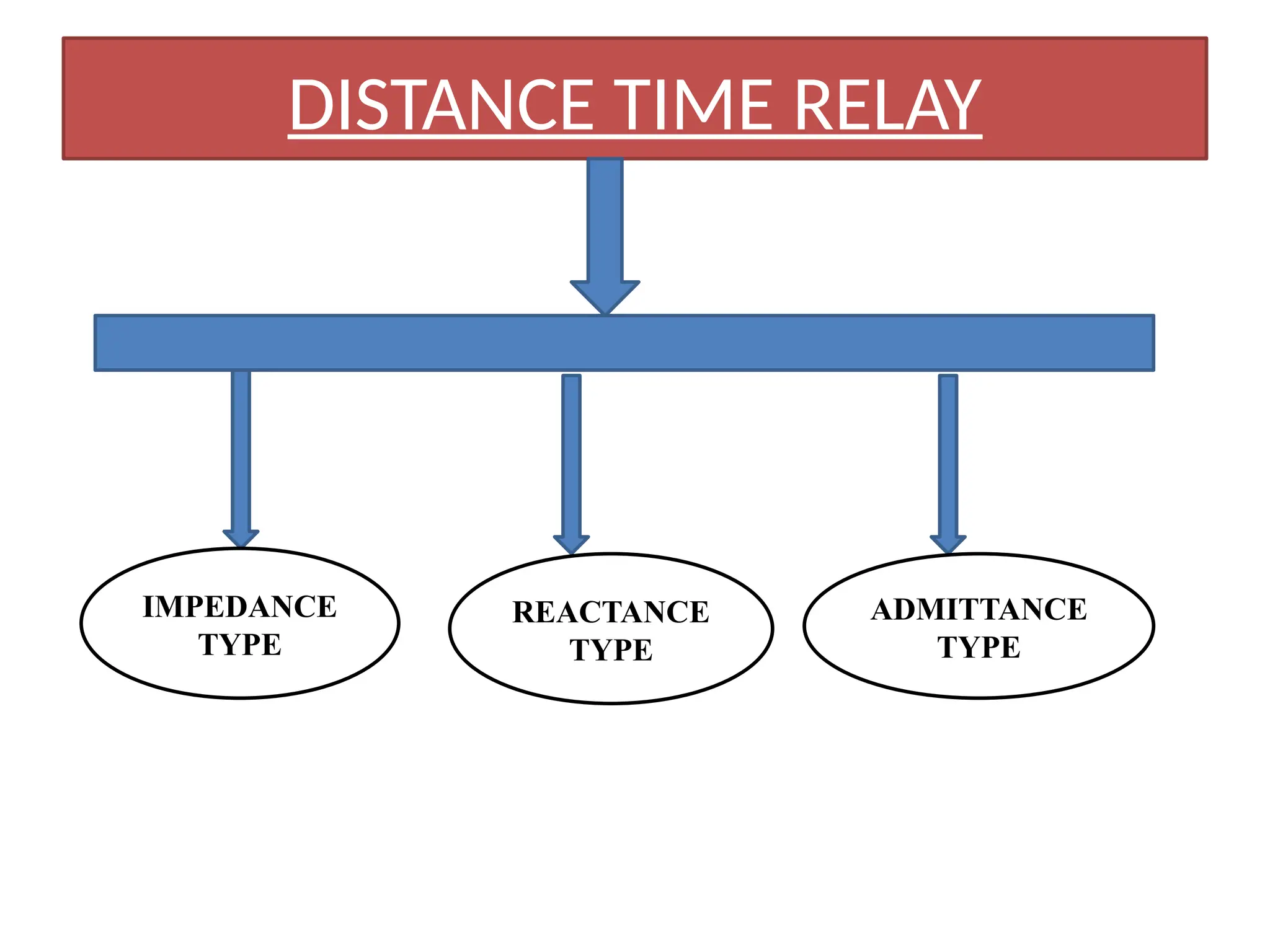
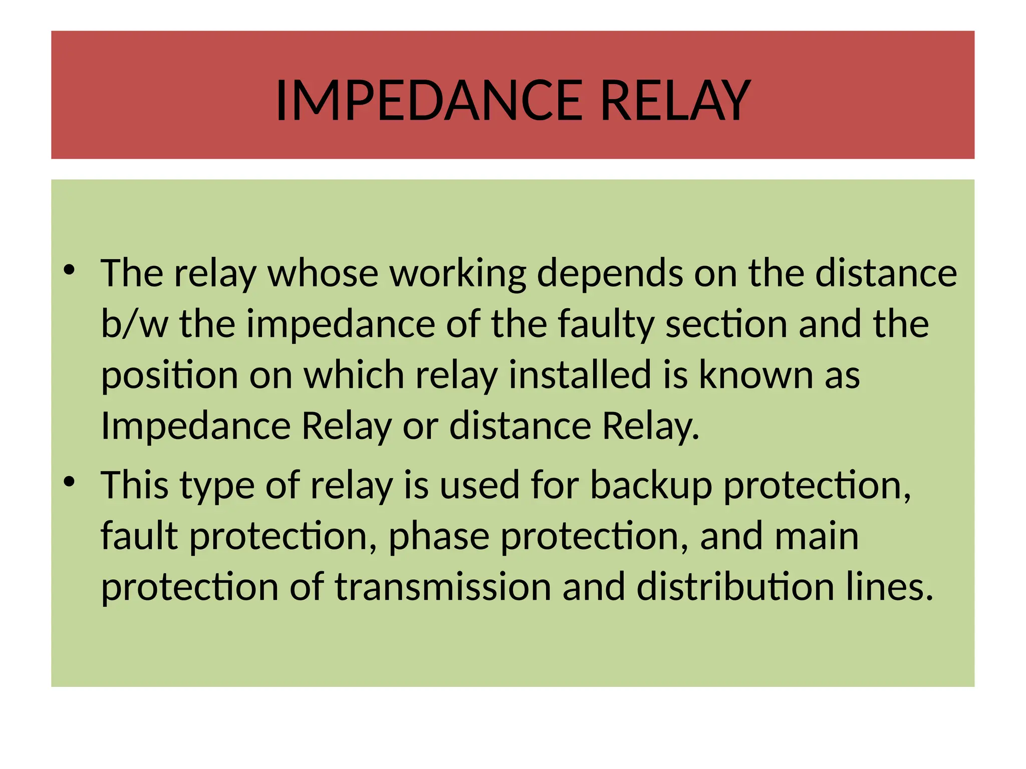
IMPEDANCE RELAY
• Therelay whose working depends on the distance
b/w the impedance of the faulty section and the
position on which relay installed is known as
Impedance Relay or distance Relay.
• This type of relay is used for backup protection,
fault protection, phase protection, and main
protection of transmission and distribution lines.
47.
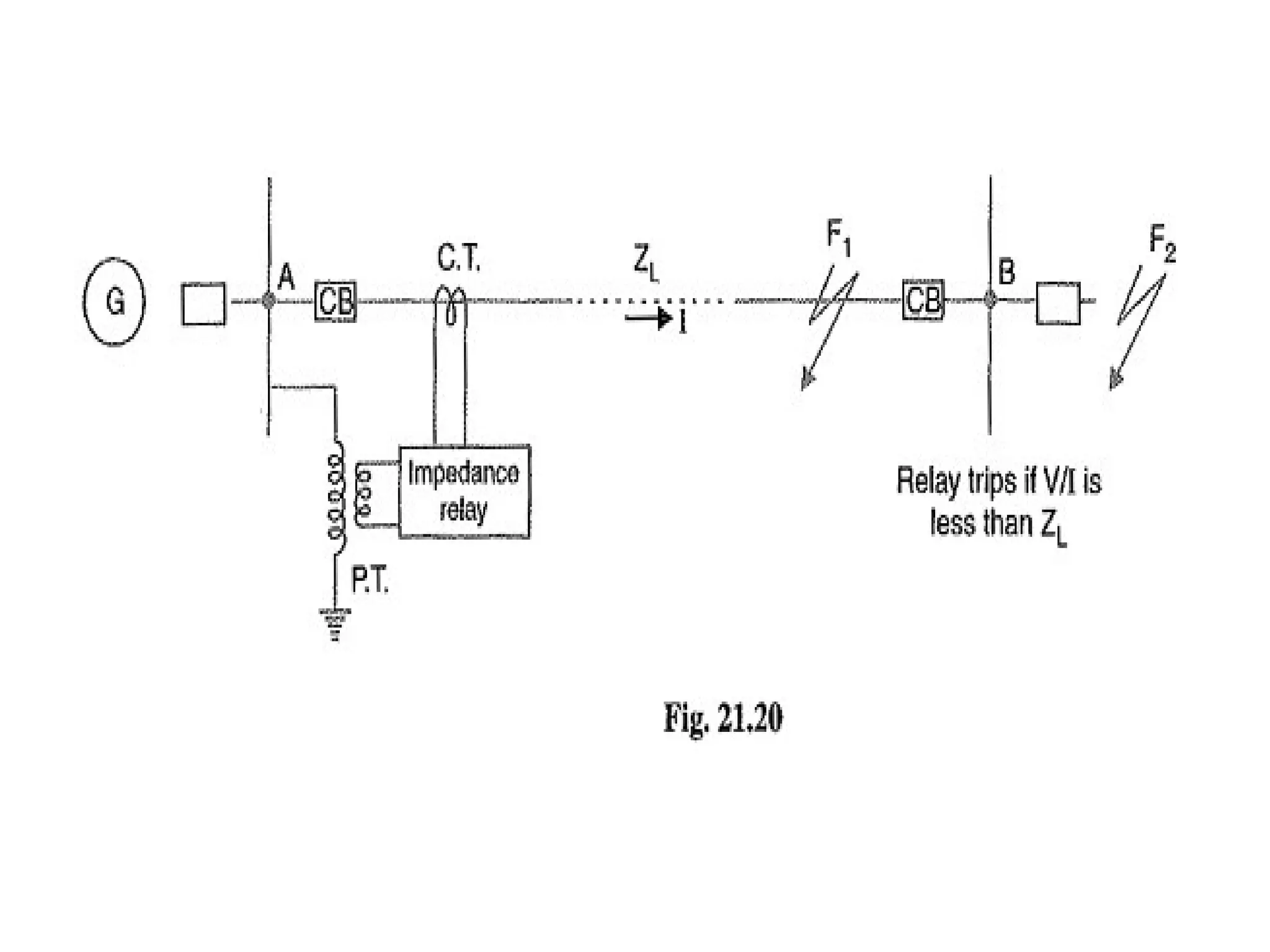
Construction
• It consistof CT, connected in the series of transmission
line, which supplies the current to the transmission line.
Deflecting torque is produced by the secondary current of
CT.
• It consist of PT, which supplies the voltage to the
transmission line, Voltage produces restoring torque.
• It consist of impedance measuring device, which measure
the ratio of voltage and current.
• A and B are the zone which is to be protected, Circuit
breaker are installed on both sides of the protective zone.
48.
Working
• The distancerelay working principle is very simple and it is
based on the ratio of voltage and current i.e, impedance.
• It is a voltage controlled equipment.
• It’s working mainly depends on the distance between the
impedances of the points where the fault occurs and where the
relay is installed (feeding point).
• The relay gets operated when the ratio of voltage and current is
set to a predetermined value or less than the relay.
• This relay contains a potential transformer to supply voltage and
current transformer for the current element, which is connected
in series with the entire circuit.
• The secondary current of CT produces the deflecting torque
whereas the potential transformer produces restoring torque.
49.
Working
• The torqueneeded to move the pointer over a
calibrated scale is known as deflecting torque.
• Controlling torque is damping torque.
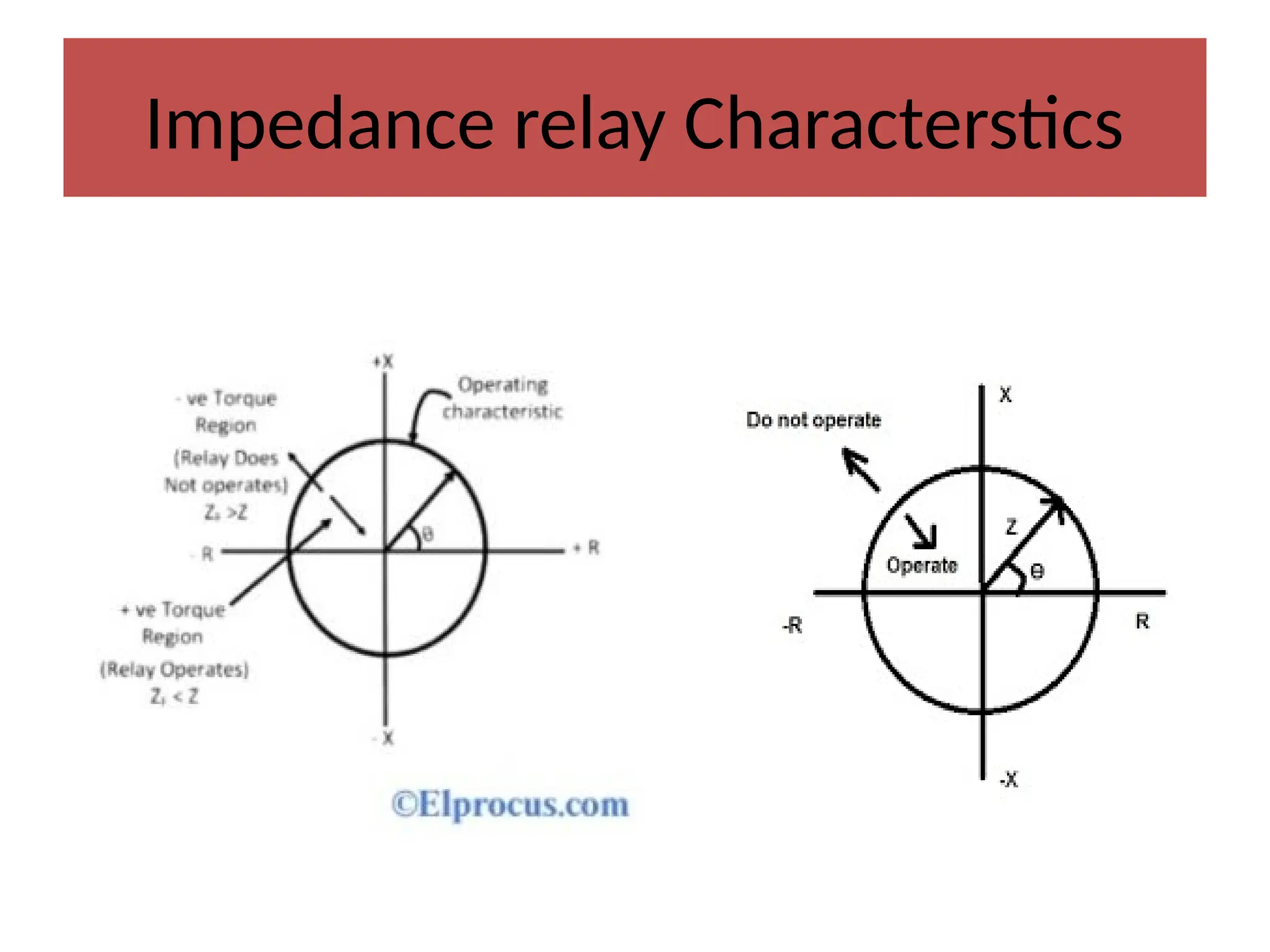
• Normal operating condition:-Under normal
operating conditions, the impedance of the
protected zone is ZL. The relay is so designed that
it closes its contacts whenever impedance of the
protected section falls below the pre-determined
value i.e.ZL .
50.
Working
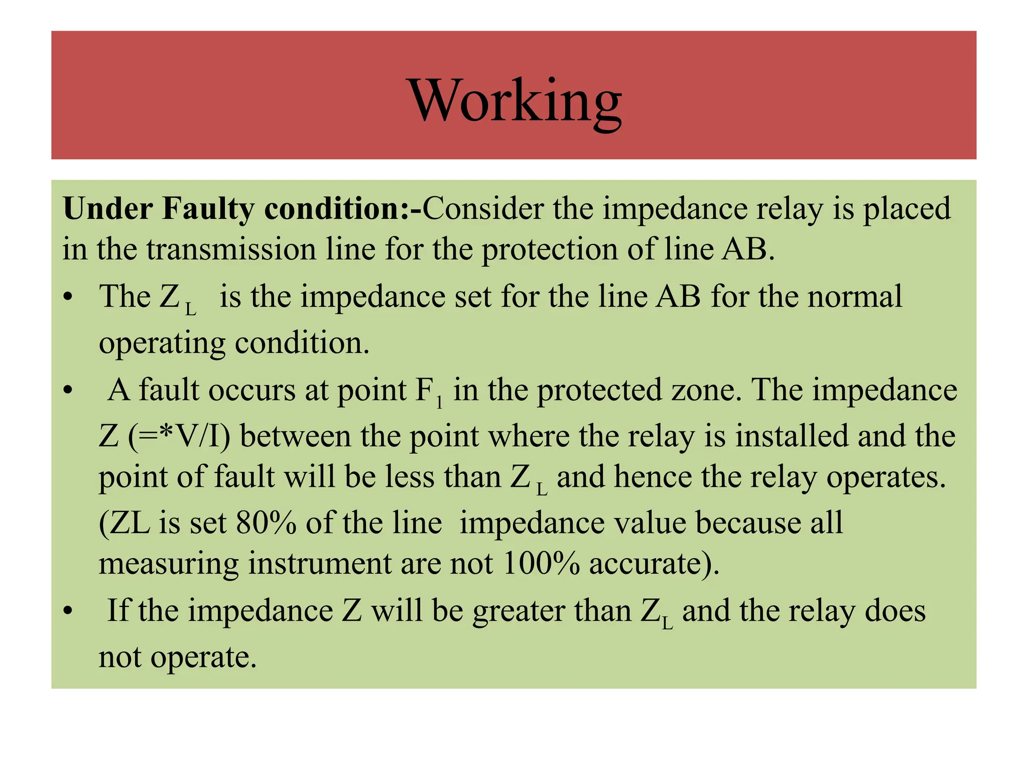
Under Faulty condition:-Considerthe impedance relay is placed
in the transmission line for the protection of line AB.
• The ZL is the impedance set for the line AB for the normal
operating condition.
• A fault occurs at point F1 in the protected zone. The impedance
Z (=*V/I) between the point where the relay is installed and the
point of fault will be less than Z L and hence the relay operates.
(ZL is set 80% of the line impedance value because all
measuring instrument are not 100% accurate).
• If the impedance Z will be greater than ZL and the relay does
not operate.
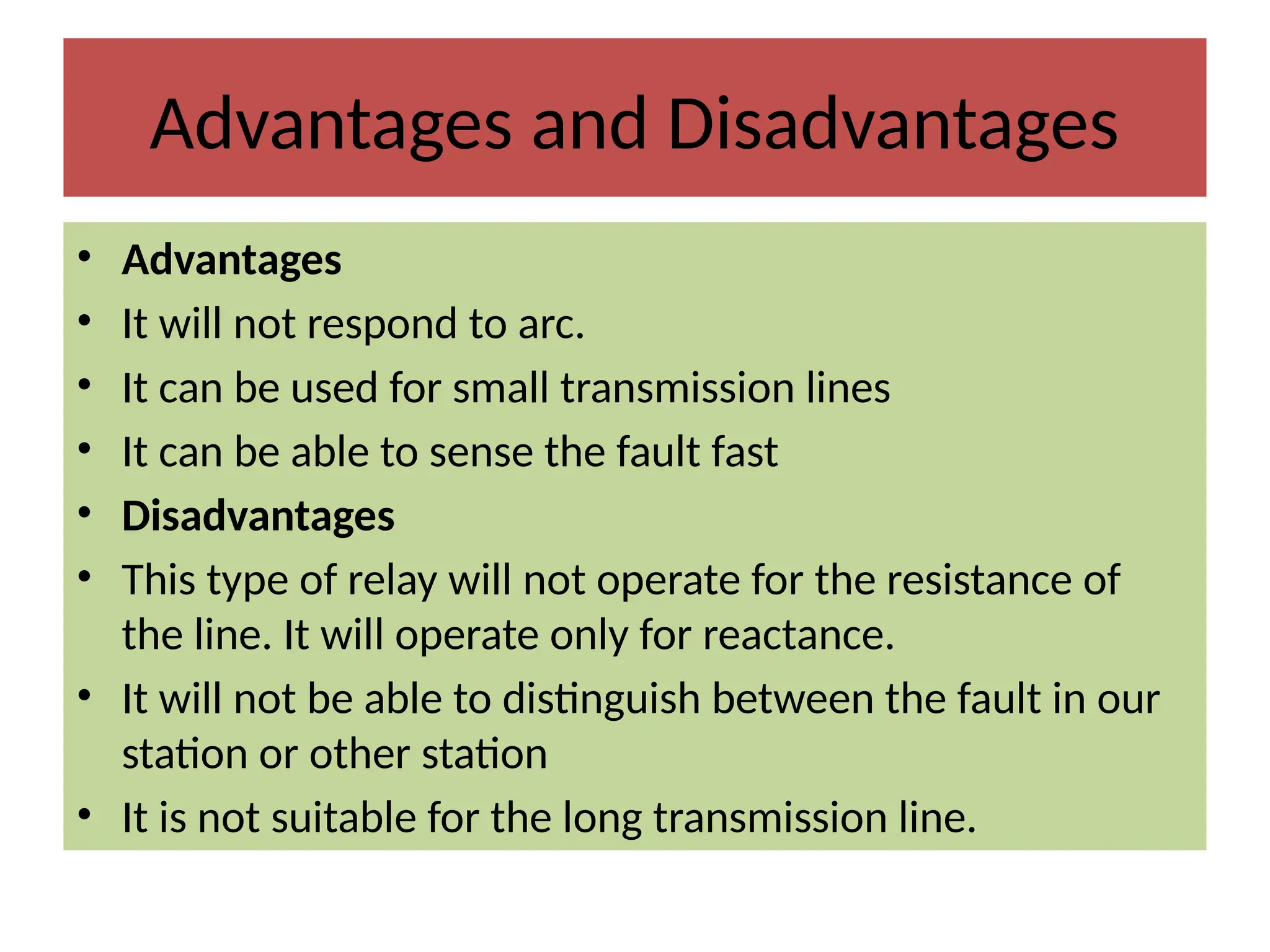
Advantages and Disadvantages
•Advantages
• It will not respond to arc.
• It can be used for small transmission lines
• It can be able to sense the fault fast
• Disadvantages
• This type of relay will not operate for the resistance of
the line. It will operate only for reactance.
• It will not be able to distinguish between the fault in our
station or other station
• It is not suitable for the long transmission line.
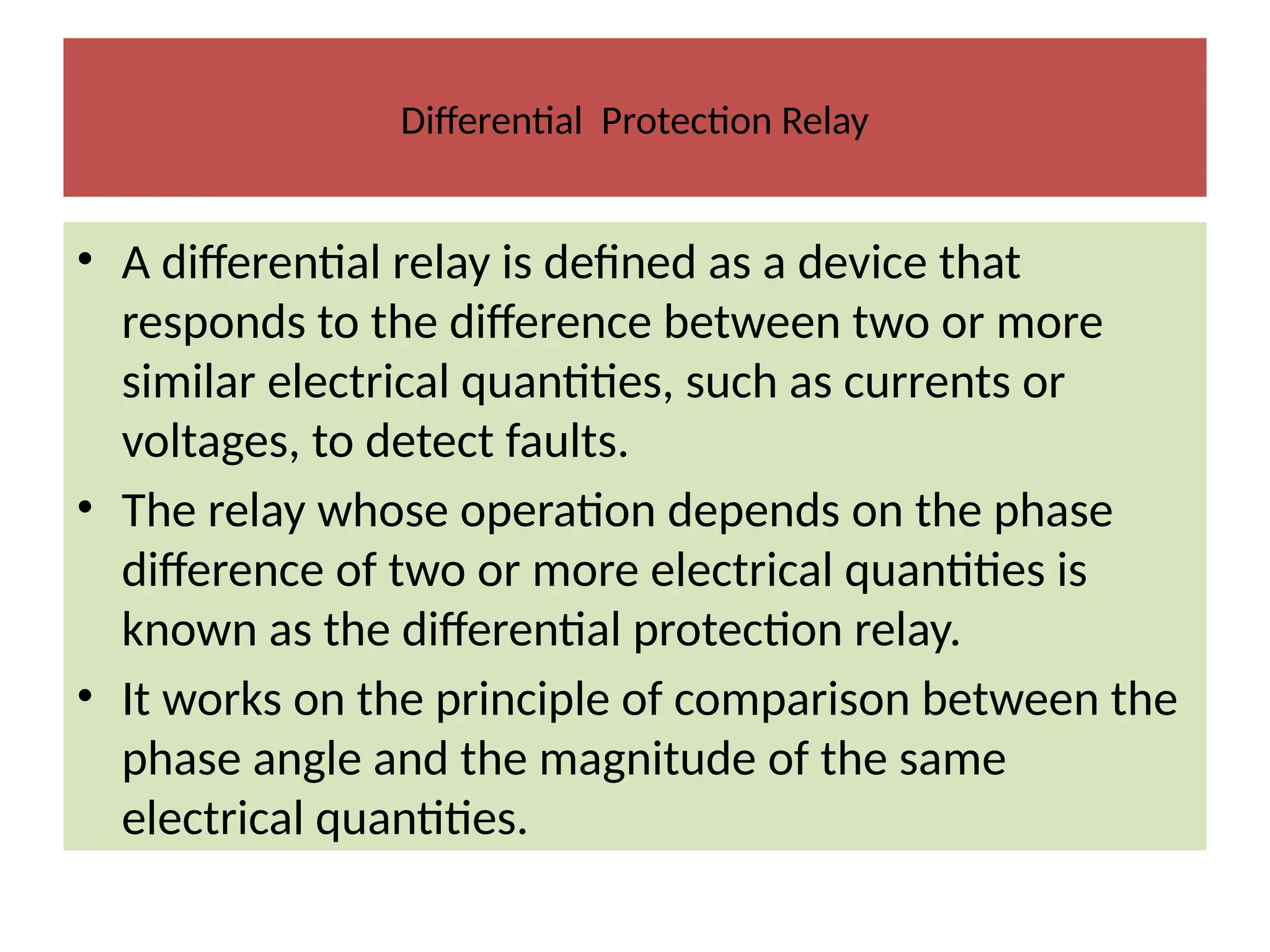
Differential Protection Relay
•A differential relay is defined as a device that
responds to the difference between two or more
similar electrical quantities, such as currents or
voltages, to detect faults.
• The relay whose operation depends on the phase
difference of two or more electrical quantities is
known as the differential protection relay.
• It works on the principle of comparison between the
phase angle and the magnitude of the same
electrical quantities.
55.
Differential Protection Relay
•For example: Consider the comparison of the input and output
current of the transmission line. If the magnitude of the input
current of the transmission line is more than that of output
current that means the additional current flows through it
because of the fault. The difference in the current can operate
the differential protection relay.
• The following are the essential condition requires for the
working of the differential protection relay.
• The network in which the relay use should have two or more
similar electrical quantities.
• The quantities have the phase displacement of approximately
180º.
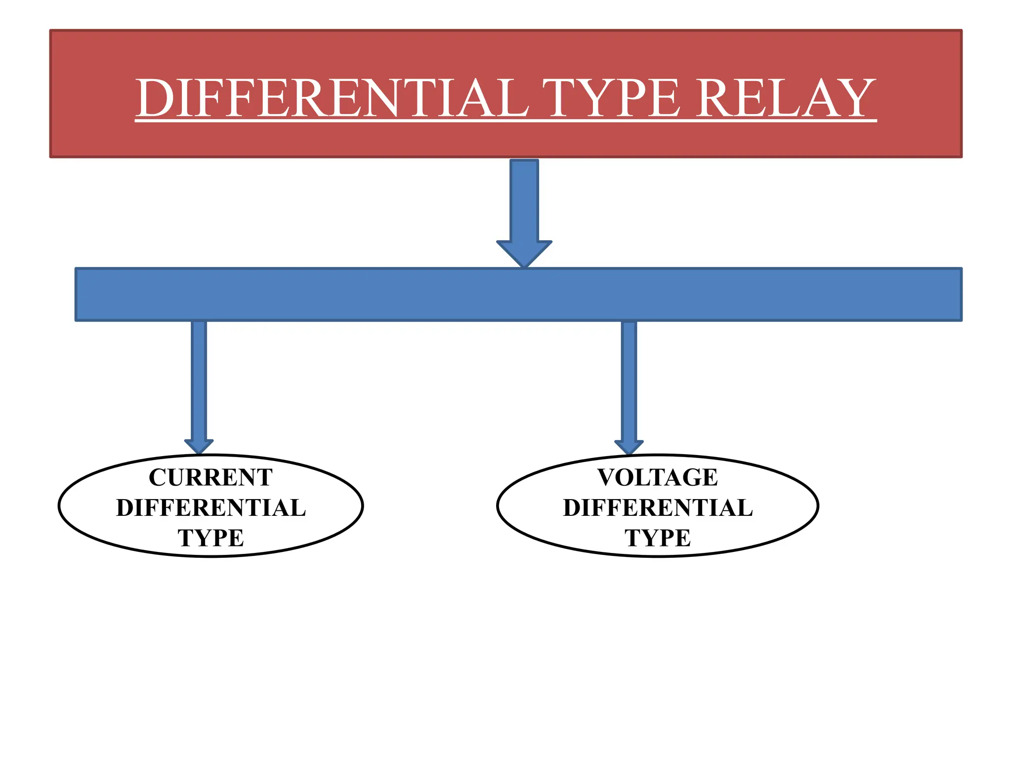
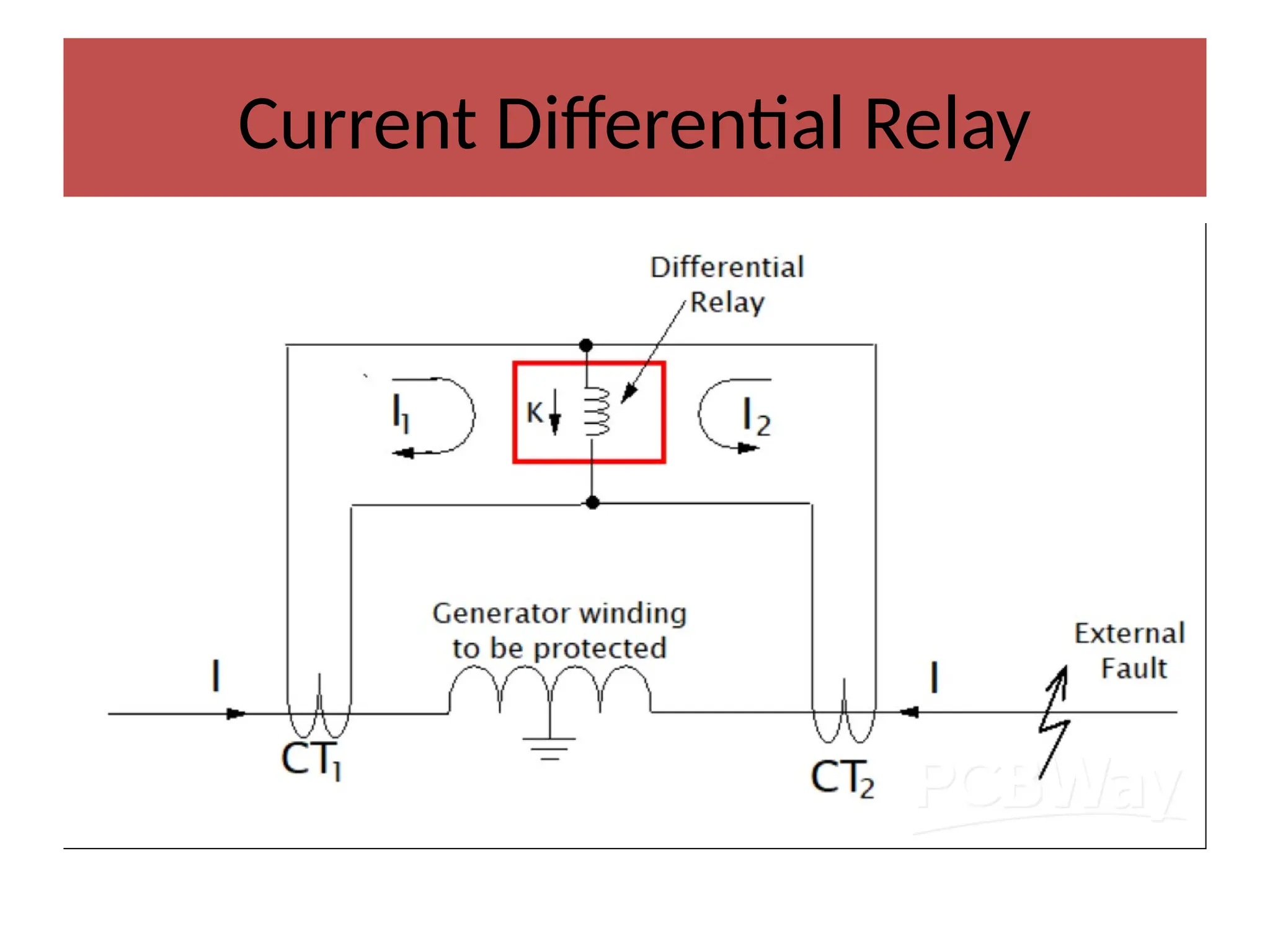
Current differential Relay
•The relay which senses and operates the
phase difference between the current
entering into the electrical system and the
current leaving the electrical system is called a
current differential relay.
• An arrangement of overcurrent relay
connected to operate as a differential relay is
shown in the figure below.
60.
Current differential Relay
•The dotted line shows the section which is
used to be protected.
• The current transformer is placed at both the
ends of the protection zone.
• The secondary of the transformers is
connected in series with the help of the pilot
wire. Thereby, the current induces in the CTs
flows in the same direction.
61.
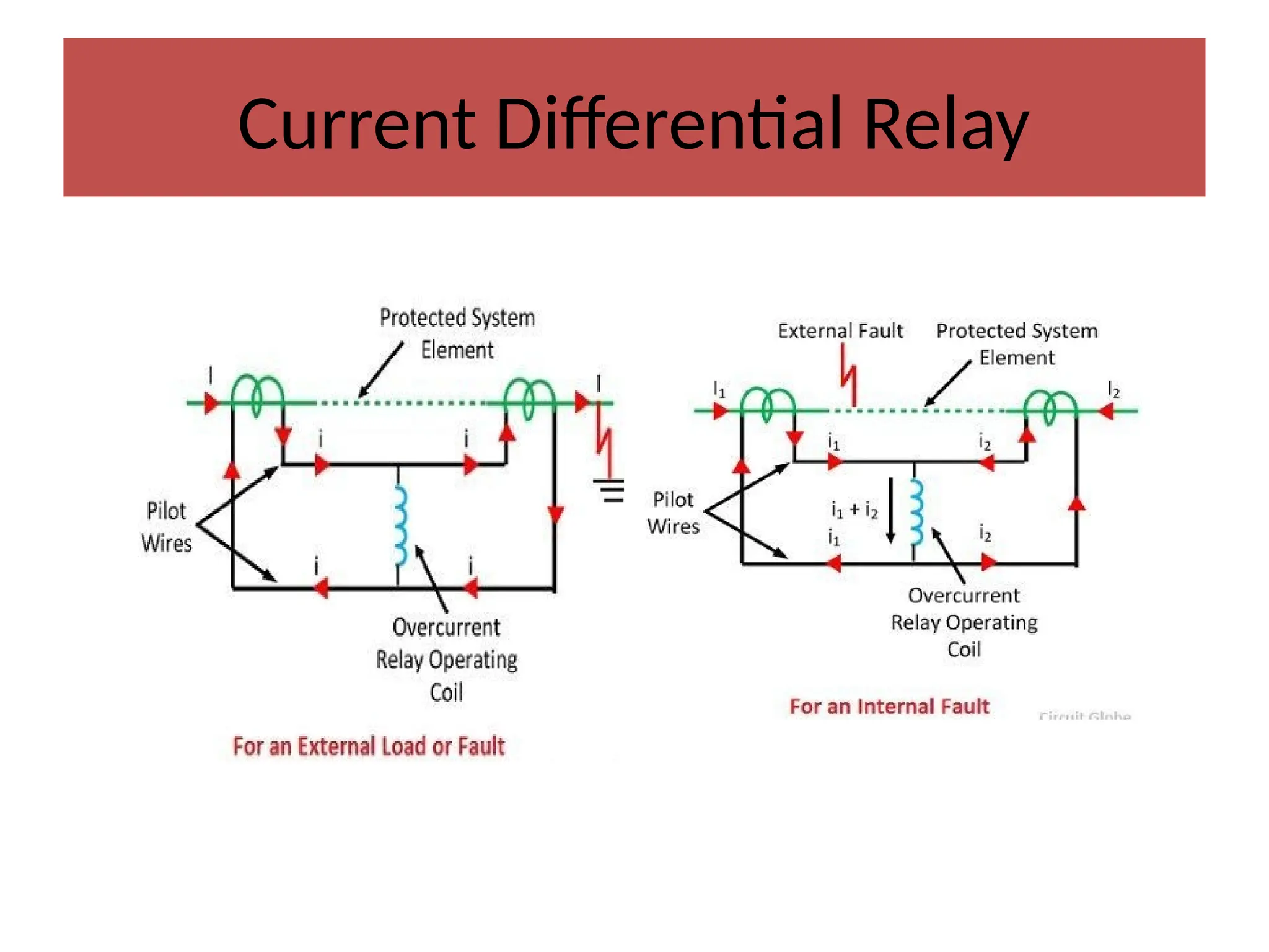
Working
• In thenormal operating condition, the magnitude of current in the
secondary of the CTs remains same. no flow of current throughout the
relay coil in normal conditions. So that malfunctioning of the relay can
be avoided.
• In normal & external fault conditions from the above circuit, the flow
of current moving into the protected region is equivalent to the flow of
current going away from the protected region (I1 – I2 = 0). Therefore
no flow of current will be there throughout the relay coil. So, it
remains out of service.
• The zero current flows through the operating coil. On the occurrence
of the fault, the magnitude of the current on the secondary of CTs
becomes unequal because of which the relay starts operating.
62.
Working
• UNDER NORMAL:-Theoperating coil of the relaying element is
connected across the CT’s secondary circuit. Under normal operating
conditions, the protected equipment (either power transformer or
alternator) carries normal current.
• In this situation, say the secondary current of CT1 is I1 and secondary
current of CT2 is I2. It is also clear from the circuit that the current
passing through the relay coil is nothing but I1-I2. No flow of current
throughout the relay coil in normal conditions (I1 – I2 = 0).
• Now if any fault occurs in the external to the zone covered by the CTs,
faulty current passes through primary of the both current transformers
and thereby secondary currents of both current transformers remain
same as in the case of normal operating conditions. Therefore at that
situation the relay will not be operated.
63.
Working
• UNDER FAULTYCONDITION:- But if any ground fault
occurred inside the protected equipment as shown, two
secondary currents will be no longer equal.
• In an internal fault case from the above figure, the flow of
current into the protected region is dissimilar from the
flow of current leaving it (I1 – I2 ≠ 0). So these current
flow differences are known as the circulating current
which is fed to the operating coil of the relay.
• At that case the differential relay is being operated to
isolate the faulty equipment (transformer or alternator)
from the system.
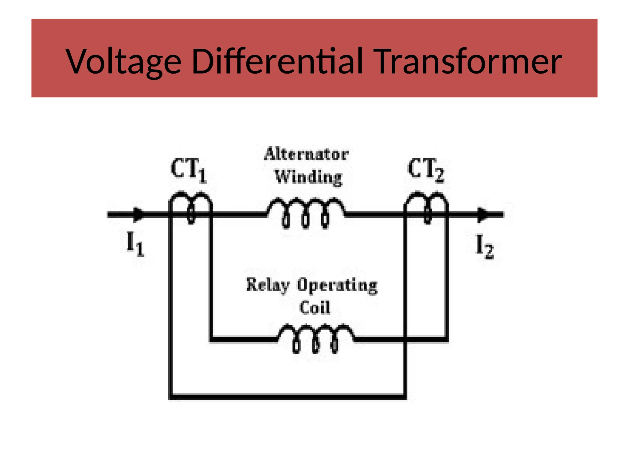
Working
• The twoCTs in the voltage balance differential
relay are simply connected at any side of
alternator to be protected.
• This type of relay simply compares two
voltages either in phase or magnitude or in
both & it trips the relay circuit if the difference
exceeds a fixed set value.
66.
Working
• The CT’sprimary windings have similar current ratios which are connected
with the pilot wire in series. These wires are connected always by simply
connecting two circuit ends as shown in the above figure & CTs secondary
winding is connected to the operating coil of the relay.
Normal operating Condition:-In the above relay circuit, the flow of current in
both the main windings of CTs will be the same at normal operating
conditions. So when the flow of current is the same, then the voltage within
the secondary winding will be the same. So, there is no flow of current in the
operating coil of a relay.
• Faulty Conditions:- A phasor difference will exist within the primary coil’s
currents. Thus, there is a difference in voltage at the second winding.
• Now a phasor difference will exist in the secondary coil’s voltage which is fed
to the operating coil of the relay and it is connected with the secondary
winding in series. Because of this, the flow of current will be there
throughout the operating coil of the relay.
67.
Advantages
• High Sensitivity:Differential relays can detect even minor imbalances
between incoming and outgoing currents, enabling them to identify
faults quickly and accurately.
• Fast Operation: The Fast response of differential relays allows for the
isolation of faulty sections, reducing the risk of equipment damage.
• Reliability: Differential relays are highly reliable in detecting internal
faults and have a low false tripping, ensuring the stability and safety
of power systems.
• Flexibility: With various types of differential relays available, they
meet the specific requirements of different power system
components, such as transformers, generators, motors, and bus bars.
68.
Disadvantages
• Differential relaysare very sensitive to the faults
occurred within the zone of protection but they are
least sensitive to the faults that occur outside the
protected zone.
• There may be a probability of mismatching in
current from CT secondary.
69.
Application
• Protection ofgenerators from faults that are
localized.
• Used in protecting the equipment against
internal faults.
• Applied to protect the windings of the
transformer.
70.
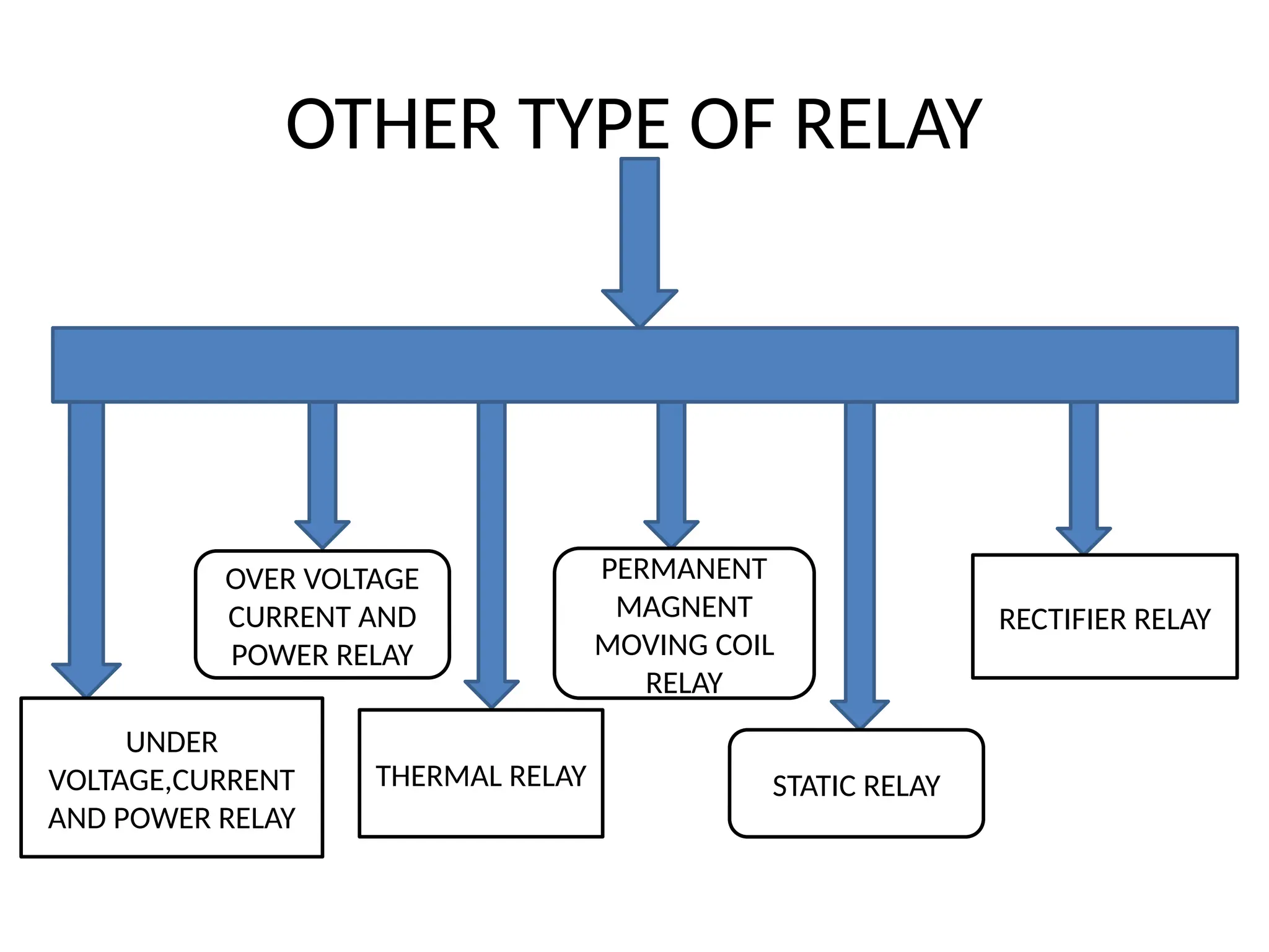
OTHER TYPE OFRELAY
UNDER
VOLTAGE,CURRENT
AND POWER RELAY
OVER VOLTAGE
CURRENT AND
POWER RELAY
THERMAL RELAY
PERMANENT
MAGNENT
MOVING COIL
RELAY
STATIC RELAY
RECTIFIER RELAY
71.
Microprocessor based overcurrentRelay
• A microprocessor relay is a type of protection relay that
uses a microprocessor to process inputs and control the
outputs of the relay system.
• Microprocessor relays are digital and programmable,
allowing for more complex and flexible functionality.
• They are widely used in modern power systems for the
protection of electrical equipment, automation, and
control.
• A microprocessor-based overcurrent relay is a device that
uses a microprocessor to protect electrical power systems
from overcurrent.
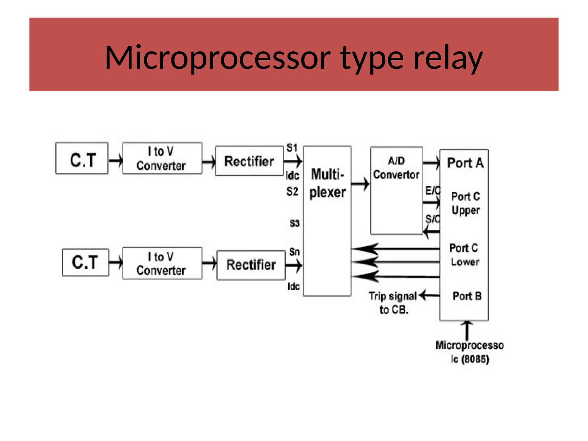
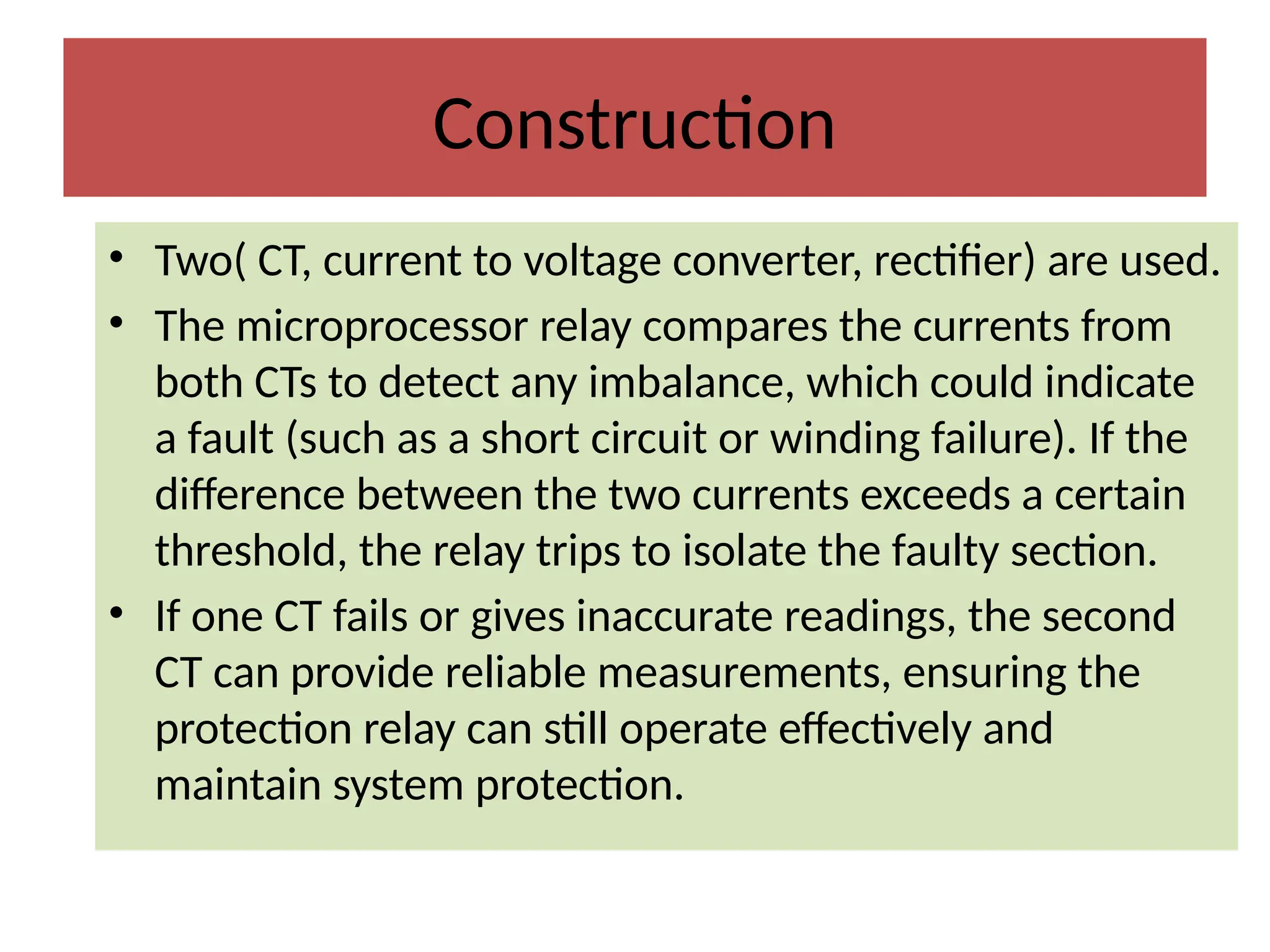
Construction
• Two( CT,current to voltage converter, rectifier) are used.
• The microprocessor relay compares the currents from
both CTs to detect any imbalance, which could indicate
a fault (such as a short circuit or winding failure). If the
difference between the two currents exceeds a certain
threshold, the relay trips to isolate the faulty section.
• If one CT fails or gives inaccurate readings, the second
CT can provide reliable measurements, ensuring the
protection relay can still operate effectively and
maintain system protection.
75.
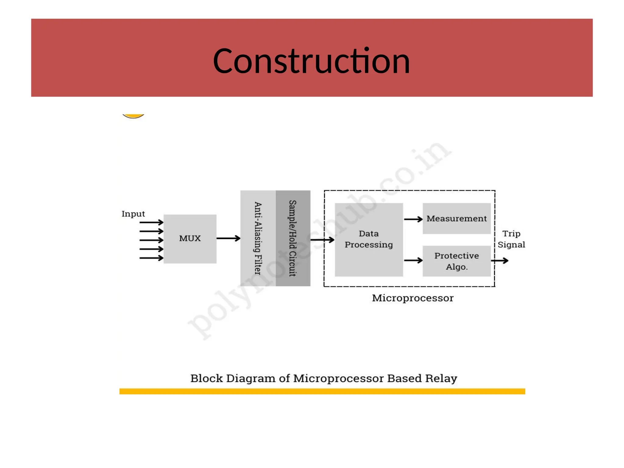
Construction
• MUX orMultiplexer: The multiplexer selects and routes different input signals to the analog-
to-digital converter (ADC). It enables the microprocessor to sample several input signals
sequentially.
• Anti-Aliasing Filter: An anti-aliasing filter is applied to the signals prior to their sampling by the
ADC. In order to avoid aliasing, which can skew the signal’s digital representation, this filter
eliminates high-frequency components from the signals.
• Sample-and-Hold (S/H): Throughout the conversion process, the sample-and-hold circuit
catches and maintains a steady level of the analog signal. This ensures that the signal remains
stable as it is translated to digital form by the ADC.
• Analog-to-Digital Converter (ADC): The ADC converts analog input signals into digital data that
can be processed by the microprocessor. It converts a continuous analog signal into discrete
digital values.
• Microprocessor: The microprocessor is the relay system’s primary processing unit. It receives
digital signals from the ADC, processes them using pre-programmed algorithms, and then
makes decisions depending on the relay’s operating logic. The microprocessor also controls the
relay’s output using internal computations and external orders.
• Output Control: The microprocessor transmits control signals to the output stage, which may
include trip signals to open circuit breakers or other control actions to address power system
problems or abnormalities.
76.
Working
• Current istaken from C.T. and given to I to V converter because many electronics circuit
require voltage signal for operation.
• The A.C. voltage is converted into D.C. voltage by using rectifier.
• This D.C. voltage is proportional to load current only.(the voltage reflects changes in the
load's current).
• The output of rectifier is given to Multiplexer.
• The Multiplexer gives output to A/D Converter where Analog DC voltage is converted to
Digital form (in form of O and 1 i.e. binary form).
• Microprocessor understands only codes in 0 and 1 form.
• Microprocessor gives S/C (start of conversion) signal to A/D converter (I.e. analog to
digital conversion is started and microprocessor gives permission to A/D convertor for
this by sending S/C)
• When converting from analog to digital is over (finish) then A/D converter sends E/C
signal to microprocessor (E/C – End of Conversion).
• When work of A/D is over then up compare the magnitude of this incoming current with
required current value (I.e. set value or reference value).
• If incoming value is more – fault is occurring and trip signal is send to CB circuit breaker.
77.
Advantages
• Very efficientand reliable.
• Highly accurate.
• Very fast in operation.
• Programmable in nature. The program can handle the online calculations and make the decision.
• A unit can perform retransmission of several systems. (Retransmission refers to the process of sending
data or a message again after a failure or error in the initial transmission. It is commonly used in
communication systems, computer networks, and telecommunications to ensure that data is accurately
received)
• Economical for large systems.
• Useful for centrally coordinated backup protection.
• They can detect issues precisely and quickly, reducing downtime and protecting equipment.
• They monitor motor performance and respond quickly to avoid motor damage or failure.
• They monitor motor performance and respond quickly to avoid motor damage or failure.
• The digital processing capabilities of microprocessors allow for exact measurement and analysis of
electrical characteristics.
• These relays can be programmed and adjusted to meet different system needs and operating situations.
• Microprocessor-based relays frequently include built-in event recording capabilities, allowing engineers to
examine system performance under abnormal conditions.
78.
Disadvantages
• Complexity OfProgramming:- Microprocessor relays require skilled personnel for setup, programming,
and troubleshooting, making them more complex compared to traditional electromechanical relays.
• Skill and learning: Operators and engineers need specialized knowledge to operate, maintain, and update
microprocessor relays effectively.
• Initial Cost:-Microprocessor relays tend to be more expensive initially compared to conventional relays.
This includes the cost of hardware, software, and training.
• Cyber security Risks:- As digital devices connected to communication networks, microprocessor relays
can be targeted by cyber attacks.
• Power Supply Dependency:-Microprocessor relays rely on an external power supply. If power is lost or
the backup fails, the relay will not function, which may be critical in fault conditions.
• Environmental Sensitivity:- These relays can be sensitive to extreme environmental conditions like high
temperatures, humidity, or electromagnetic interference, potentially reducing their reliability in harsh
environments.
• Updates:- Frequent updates may be required to ensure the relay functions correctly, which can lead to
temporary system disruptions.
• Maintenance Costs: Long-term costs may increase due to the need for regular updates, calibrations, and
maintenance.
• Software Bugs: As microprocessor relays rely on software, there is a risk of bugs or errors in the
programming, which could result in incorrect operations or failures in protective actions.
• Processing Delay: In rare cases, microprocessor-based systems may experience slight delays due to the
time taken for the processor to analyze data and execute commands, although this is typically minimal.
• Shorter Lifespan:-Microprocessor technology advances rapidly, leading to shorter lifecycles compared to
electromechanical relays, which can function for decades with minimal maintenance.
79.
Application
• Microprocessor relayis used to protect power systems from
problems such as overcurrent, overvoltage, under voltage, and
frequency fluctuations.
• In industrial applications, microprocessor-based relays are used to
safeguard motors against overloads, phase imbalances, and other
electrical anomalies.
• They monitor motor performance and respond quickly to avoid
motor damage or failure.
• Microprocessor-based relays can communicate over networks,
allowing for remote monitoring and control of electrical systems.
• They monitor motor performance and respond quickly to avoid
motor damage or failure.
80.
Application
•Transformer Protection: Monitoringand protecting transformers from faults
such as overcurrent, under frequency, and differential issues.
•Generator Protection: Guarding generators against abnormal operating
conditions, including overvoltage, under frequency, or imbalance.
•Motor Protection: Protecting motors from conditions such as overload,
under load, and phase failure.
•Feeder Protection( distribution line): Managing the protection of
distribution lines to prevent damage from overloads and short circuits.
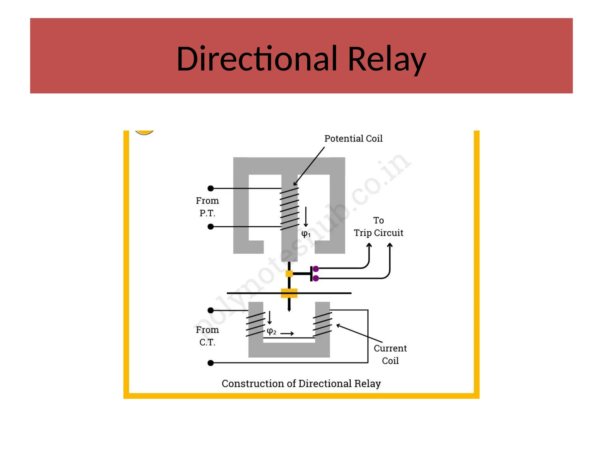
Construction and Working
•PT:-which reduces the voltage of the power system to a level
that the relay can process.
• CT:-current transformers that reduce the current flowing
through the power supply to a level suitable for the relay to
manage. The current transformers send a proportional current
signal to the relay based on the current flow in the system.
• Potential coil:- also called the voltage coil, is a winding inside
the relay that receives the voltage signal from the potential
transformer. It is normally linked in parallel with the system
and serves as a reference for determining the direction of
power flow.
84.
Construction and Working
•Current coil, also known as the directional coil,
receives current signals from the current
transformers. It is normally connected in series
with the system, generating a magnetic field
proportionate to the current running through
it.
• Tripping Circuit:- It perform the tripping
mechanism for the circuit breaker when a fault
is identified.
85.
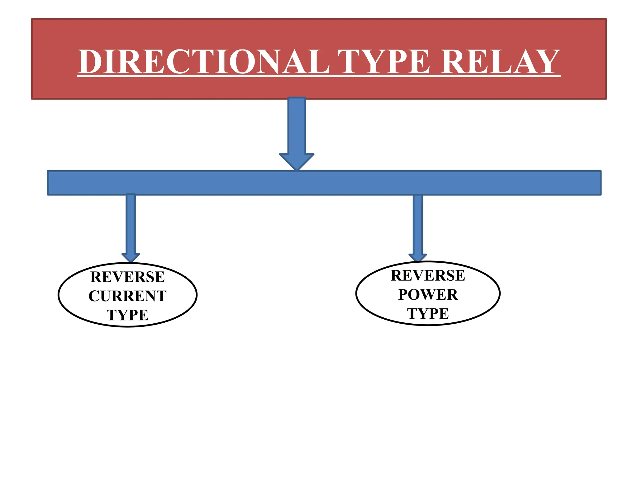
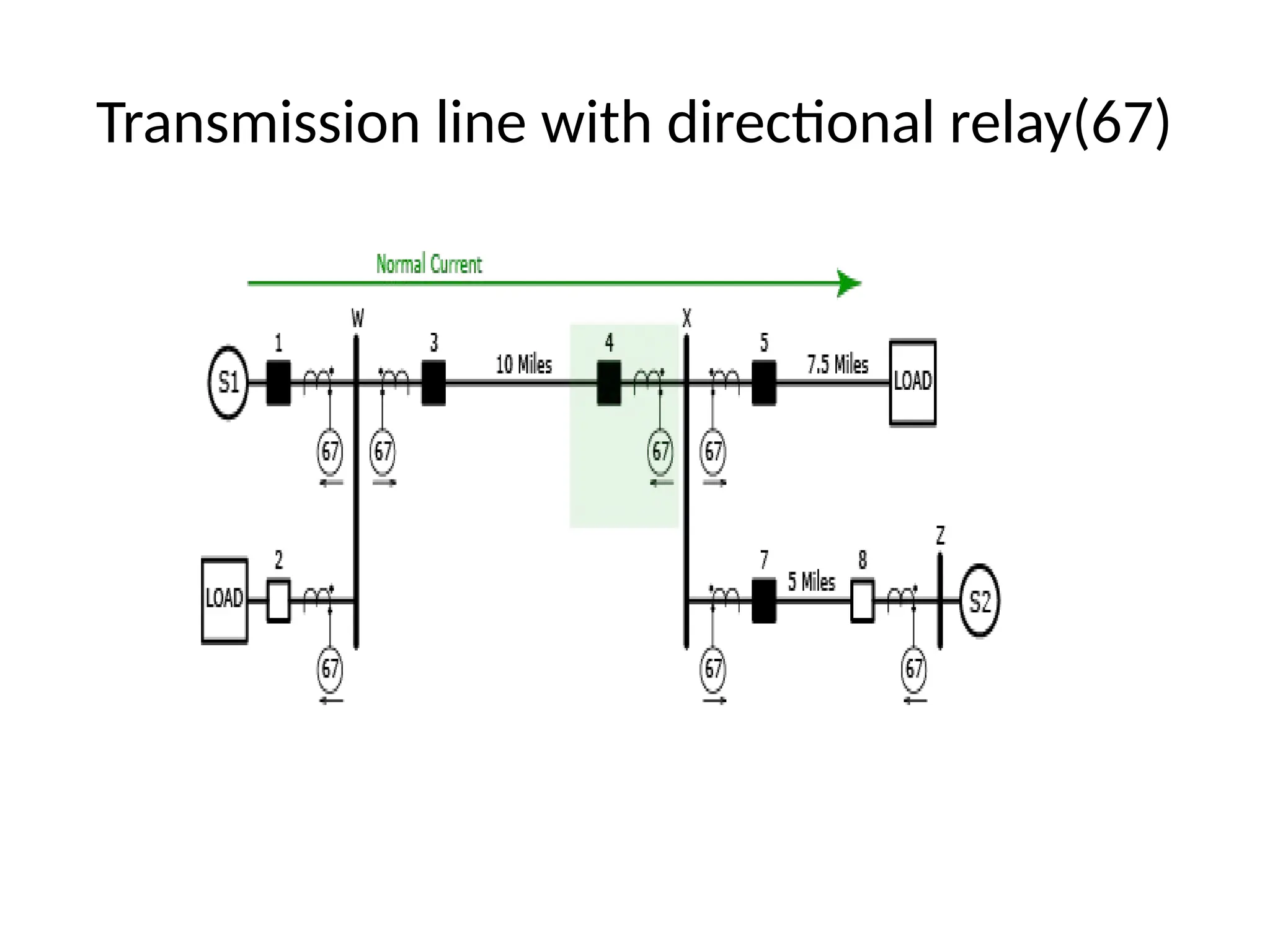
WORKING
• The directionalrelay identifies whether the fault is in the forward or backward direction by
comparing the voltage and current signals received from the potential and current coils. If a
failure is identified in the forward direction, the relay transmits a trip signal to the circuit
breaker, which isolates the faulty component of the system in forward and vice versa.
• The relay constantly monitors the current and voltage signals from the CTs and PTs,
respectively. These transformers reduce the current and voltage levels to reasonable amounts
for the relay to handle.
• The relay compares the phase angle of the current and voltage signals. By examining the
phase connection between current and voltage, the relay can determine the direction of power
flow in the electrical circuit.
• Normal condition:-Based on specified parameters and logic, the relay determines whether the
current flow is in the intended (ahead) or opposing (reverse) direction. If the current flows in
the forward direction according to the established values, it indicates normal operation. Faulty
condition:-However, if the current flows in the opposite direction or exceeds predefined
thresholds, signaling a failure, the relay takes preventative action.
• When the directional relay detects a fault or abnormal state, it sends a trip signal to the circuit
breaker connected with the faulty component of the system. This step separates the system,
preventing equipment damage while also ensuring the electrical network’s stability and safety.
• https://relaytraining.com/finding-directional-overcurrent/ link for directional relay
working(brief understanding).
86.
Advantages
• Timely disconnectingfrom abnormal currents prevents
equipment damage.
• The decreased likelihood of electrical mishaps and fires
improves overall safety.
• Reduced unnecessary tripping of circuit breakers
improves system efficiency.
• Adjustable settings enable customisation to meet
unique system needs.
87.
Disadvantages
• Directional relaysare typically more expensive.
• Determining the direction of a fault can take slightly more
time compared to simpler relays, which might cause minimal
delays in tripping during fault conditions.
• Directional relays depend on a reliable voltage reference to
determine the direction of the fault. If there is a voltage drop,
or if the voltage becomes too low during a fault condition, the
relay may fail to operate or give an incorrect response.
88.
Application
• Installed toprotect transformers, circuit breakers,
and other substation equipment from faults,
hence ensuring transmission system reliability.
• Used to protect electrical equipment and humans
in mines where electrical risks are common.
• Employed to protect important machinery and
equipment from electrical problems, reducing
downtime and production losses.