Download as PDF, PPTX


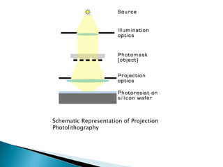
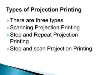


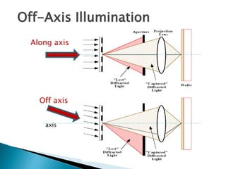


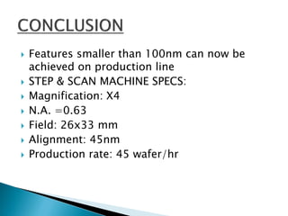


Projection photolithography involves focusing the image of a photomask onto a wafer through an optical system. There are three main types: scanning projection, step-and-repeat, and step-and-scan. Techniques to improve resolution below the diffraction limit include off-axis illumination, proximity optical correction, and phase-shift masks. While decreasing the wavelength and increasing numerical aperture improve resolution, it reduces depth of field, requiring additional techniques. Modern step-and-scan machines can achieve features smaller than 100nm.


