Download to read offline
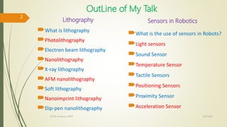
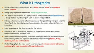
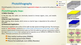
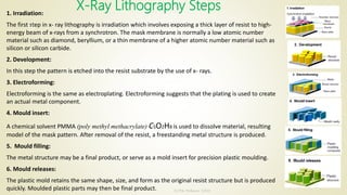
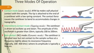


This document outlines Dr. P. Senthilkumar's talk on various lithography techniques. It begins with an introduction to lithography, then discusses specific techniques like photolithography, electron beam lithography, nanolithography, and x-ray lithography. For photolithography, it provides detailed steps including wafer cleaning, photoresist application, exposure, development, and etching. It also discusses applications of lithography in microelectronics fabrication.


![Thin_Film_Technology_introduction[1]](https://cdn.slidesharecdn.com/ss_thumbnails/1b4496c8-2102-411b-8465-a3dd3f398327-150205034538-conversion-gate02-thumbnail.jpg?width=640&height=640&fit=bounds)


