Downloaded 457 times


![MANUFACTURING DEPARTMENT
TYPES OF CNC MACHINES
1} CNC LATHE MACHINE
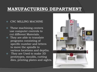
2} CNC MILLING MACHINE
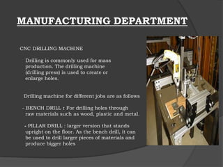
3} CNC DRILLING MACHINE
- BENCH DRILL
- PILLAR DRILL
4} CNC BORING MACHINE
5} CNC GRINDING MACHINE
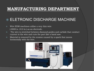
6} ELECTRONIC DISCHARGE MACHINE [EDM]
7} LASER CUTTING MACHINE](https://image.slidesharecdn.com/productiontechnologyppt-130901104346-phpapp02/85/Production-technology-ppt-18-320.jpg)


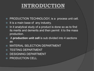
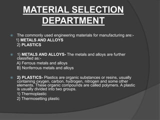
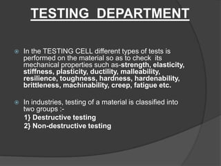
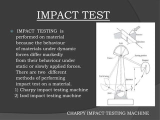
This document provides a summary of a minor training report on production technology. It discusses the various departments within a production unit cell, including the material selection, testing, designing, and manufacturing departments. The material selection department chooses between metals, alloys, and plastics. The testing department evaluates materials through destructive tests like tensile and impact tests, as well as non-destructive tests. The designing department uses CAD and CAM software. Finally, the manufacturing department machines parts using CNC lathes, mills, drills, and other tools programmed based on the CAD/CAM designs.


