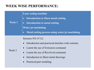
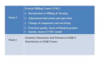
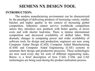
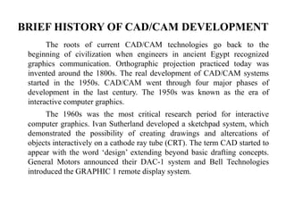
The document provides information about an internship at HRS Engineering Solutions in Bangalore, India. It discusses the company profile, vision, and mission. It then details the intern's weekly activities, including learning Siemens NX software, laser beam machining, vertical milling, water jet machining, and geometric dimensioning and tolerancing. The intern gained experience operating machines and designing parts. The summary provides an overview of the key learnings and experiences from the internship.
THIS PPT CONTAIN VMC TRAINING AT GHANDHY COLLEGE SURAT. THIS INCLUDE ABOUT CNC MACHINE, AXIS IDENTIFICATIONS, PART PROGRAMMING, G CODES, M CODES,OPERATING OF VMC....SIMPLE DRAWING FOR VMC INCLUDING LINEAR N CIRCULAR INTERPOLATIONS
Producing hole is one of the most common machining operation on a machining center.
Machining center have many hole making cycles such as Spot Drilling, Reaming, Deep Hole drilling, Peck drilling etc.
in this Ppt all canned cycle are explained i;e G70 G71 G72 G73 G75 G76 G81
Computer Numerical Control (CNC) Machining is the process through which computers control machine-based processes in manufacturing. The kinds of machines controlled include lathes, mills, routers and grinders – all used for manufacturing of metal and plastic products.
In the manufacturing sector, accuracy is vital. To guarantee top performance and quality, each part and every detail must match precisely. Let us introduce CNC drilling machines, which are revolutionizing modern manufacturing. Let us explore how these devices are opening up new possibilities and changing manufacturing processes.
DesignSpark mechanical martin keenan launch budapest 2013MartinKeenan
this is a slidepack from the launch of DesignSpark Mechanical - 3D design for every engineer. A collaboration between RS Components, Allied Electronics and SpaceClaim, featuring TraceParts
designspark mechanical 3d printing design software freeMartinKeenan
free 3d design software for electronics automation industrial engineering 3d printing concepts prototypes and more
learn more and get your copy today at www.designspark.com/mechanical
Final project report on grocery store management system..pdfKamal Acharya
In today’s fast-changing business environment, it’s extremely important to be able to respond to client needs in the most effective and timely manner. If your customers wish to see your business online and have instant access to your products or services.
Online Grocery Store is an e-commerce website, which retails various grocery products. This project allows viewing various products available enables registered users to purchase desired products instantly using Paytm, UPI payment processor (Instant Pay) and also can place order by using Cash on Delivery (Pay Later) option. This project provides an easy access to Administrators and Managers to view orders placed using Pay Later and Instant Pay options.
In order to develop an e-commerce website, a number of Technologies must be studied and understood. These include multi-tiered architecture, server and client-side scripting techniques, implementation technologies, programming language (such as PHP, HTML, CSS, JavaScript) and MySQL relational databases. This is a project with the objective to develop a basic website where a consumer is provided with a shopping cart website and also to know about the technologies used to develop such a website.
This document will discuss each of the underlying technologies to create and implement an e- commerce website.
Hybrid optimization of pumped hydro system and solar- Engr. Abdul-Azeez.pdffxintegritypublishin
Advancements in technology unveil a myriad of electrical and electronic breakthroughs geared towards efficiently harnessing limited resources to meet human energy demands. The optimization of hybrid solar PV panels and pumped hydro energy supply systems plays a pivotal role in utilizing natural resources effectively. This initiative not only benefits humanity but also fosters environmental sustainability. The study investigated the design optimization of these hybrid systems, focusing on understanding solar radiation patterns, identifying geographical influences on solar radiation, formulating a mathematical model for system optimization, and determining the optimal configuration of PV panels and pumped hydro storage. Through a comparative analysis approach and eight weeks of data collection, the study addressed key research questions related to solar radiation patterns and optimal system design. The findings highlighted regions with heightened solar radiation levels, showcasing substantial potential for power generation and emphasizing the system's efficiency. Optimizing system design significantly boosted power generation, promoted renewable energy utilization, and enhanced energy storage capacity. The study underscored the benefits of optimizing hybrid solar PV panels and pumped hydro energy supply systems for sustainable energy usage. Optimizing the design of solar PV panels and pumped hydro energy supply systems as examined across diverse climatic conditions in a developing country, not only enhances power generation but also improves the integration of renewable energy sources and boosts energy storage capacities, particularly beneficial for less economically prosperous regions. Additionally, the study provides valuable insights for advancing energy research in economically viable areas. Recommendations included conducting site-specific assessments, utilizing advanced modeling tools, implementing regular maintenance protocols, and enhancing communication among system components.
About
Indigenized remote control interface card suitable for MAFI system CCR equipment. Compatible for IDM8000 CCR. Backplane mounted serial and TCP/Ethernet communication module for CCR remote access. IDM 8000 CCR remote control on serial and TCP protocol.
• Remote control: Parallel or serial interface.
• Compatible with MAFI CCR system.
• Compatible with IDM8000 CCR.
• Compatible with Backplane mount serial communication.
• Compatible with commercial and Defence aviation CCR system.
• Remote control system for accessing CCR and allied system over serial or TCP.
• Indigenized local Support/presence in India.
• Easy in configuration using DIP switches.
Technical Specifications
Indigenized remote control interface card suitable for MAFI system CCR equipment. Compatible for IDM8000 CCR. Backplane mounted serial and TCP/Ethernet communication module for CCR remote access. IDM 8000 CCR remote control on serial and TCP protocol.
Key Features
Indigenized remote control interface card suitable for MAFI system CCR equipment. Compatible for IDM8000 CCR. Backplane mounted serial and TCP/Ethernet communication module for CCR remote access. IDM 8000 CCR remote control on serial and TCP protocol.
• Remote control: Parallel or serial interface
• Compatible with MAFI CCR system
• Copatiable with IDM8000 CCR
• Compatible with Backplane mount serial communication.
• Compatible with commercial and Defence aviation CCR system.
• Remote control system for accessing CCR and allied system over serial or TCP.
• Indigenized local Support/presence in India.
Application
• Remote control: Parallel or serial interface.
• Compatible with MAFI CCR system.
• Compatible with IDM8000 CCR.
• Compatible with Backplane mount serial communication.
• Compatible with commercial and Defence aviation CCR system.
• Remote control system for accessing CCR and allied system over serial or TCP.
• Indigenized local Support/presence in India.
• Easy in configuration using DIP switches.
TECHNICAL TRAINING MANUAL GENERAL FAMILIARIZATION COURSEDuvanRamosGarzon1
AIRCRAFT GENERAL
The Single Aisle is the most advanced family aircraft in service today, with fly-by-wire flight controls.
The A318, A319, A320 and A321 are twin-engine subsonic medium range aircraft.
The family offers a choice of engines
Explore the innovative world of trenchless pipe repair with our comprehensive guide, "The Benefits and Techniques of Trenchless Pipe Repair." This document delves into the modern methods of repairing underground pipes without the need for extensive excavation, highlighting the numerous advantages and the latest techniques used in the industry.
Learn about the cost savings, reduced environmental impact, and minimal disruption associated with trenchless technology. Discover detailed explanations of popular techniques such as pipe bursting, cured-in-place pipe (CIPP) lining, and directional drilling. Understand how these methods can be applied to various types of infrastructure, from residential plumbing to large-scale municipal systems.
Ideal for homeowners, contractors, engineers, and anyone interested in modern plumbing solutions, this guide provides valuable insights into why trenchless pipe repair is becoming the preferred choice for pipe rehabilitation. Stay informed about the latest advancements and best practices in the field.
Quality defects in TMT Bars, Possible causes and Potential Solutions.PrashantGoswami42
Maintaining high-quality standards in the production of TMT bars is crucial for ensuring structural integrity in construction. Addressing common defects through careful monitoring, standardized processes, and advanced technology can significantly improve the quality of TMT bars. Continuous training and adherence to quality control measures will also play a pivotal role in minimizing these defects.
Immunizing Image Classifiers Against Localized Adversary Attacksgerogepatton
This paper addresses the vulnerability of deep learning models, particularly convolutional neural networks
(CNN)s, to adversarial attacks and presents a proactive training technique designed to counter them. We
introduce a novel volumization algorithm, which transforms 2D images into 3D volumetric representations.
When combined with 3D convolution and deep curriculum learning optimization (CLO), itsignificantly improves
the immunity of models against localized universal attacks by up to 40%. We evaluate our proposed approach
using contemporary CNN architectures and the modified Canadian Institute for Advanced Research (CIFAR-10
and CIFAR-100) and ImageNet Large Scale Visual Recognition Challenge (ILSVRC12) datasets, showcasing
accuracy improvements over previous techniques. The results indicate that the combination of the volumetric
input and curriculum learning holds significant promise for mitigating adversarial attacks without necessitating
adversary training.
CFD Simulation of By-pass Flow in a HRSG module by R&R Consult.pptxR&R Consult
CFD analysis is incredibly effective at solving mysteries and improving the performance of complex systems!
Here's a great example: At a large natural gas-fired power plant, where they use waste heat to generate steam and energy, they were puzzled that their boiler wasn't producing as much steam as expected.
R&R and Tetra Engineering Group Inc. were asked to solve the issue with reduced steam production.
An inspection had shown that a significant amount of hot flue gas was bypassing the boiler tubes, where the heat was supposed to be transferred.
R&R Consult conducted a CFD analysis, which revealed that 6.3% of the flue gas was bypassing the boiler tubes without transferring heat. The analysis also showed that the flue gas was instead being directed along the sides of the boiler and between the modules that were supposed to capture the heat. This was the cause of the reduced performance.
Based on our results, Tetra Engineering installed covering plates to reduce the bypass flow. This improved the boiler's performance and increased electricity production.
It is always satisfying when we can help solve complex challenges like this. Do your systems also need a check-up or optimization? Give us a call!
Work done in cooperation with James Malloy and David Moelling from Tetra Engineering.
More examples of our work https://www.r-r-consult.dk/en/cases-en/
Pile Foundation by Venkatesh Taduvai (Sub Geotechnical Engineering II)-conver...
Vmc.pptx
1. YENEPOYA INSTITUTE OF TECHNOLOGY
Department of Mechanical Engineering
Internship On CNC
Under Guidance of Presented by:
Prof. Venkatesh Rao Abdul Khader Shanan
4DM19ME001
2. COMPANY PROFILE
HRS Engineering Solutions is a mechanical engineering service company,
that specializes in product design, Engineering Analysis, Technical
Documentation & manufacturing Support. We believe in collaboration with
cross functional teams for effective and timely development of Ideas from
concept to manufacturing.
VISION:
Part of customer success and progress by supporting in Engineering design
and manufacturing and deliver the intended product to be competent in
market.
3. MISSION:
• Foster by creativity through knowledge sharing.
• Increase productivity through continual improvements and quality
practices.
• Raising awareness by enhancing ideas to improve the products.
• Ensuring certainty of high-quality products and on time market release.
STRATEGIC AND ENABLING PILLARS :
• Customer.
• Latest technology.
• Highly skilled workforce.
• Responsive IT infrastructure.
• Operational Excellence.
5. ABOUT THE INTERNSHIP:
The main objective of the Internship was to learn and gain knowledge
regarding the Siemens NX Version 12 software, Laser Beam Machining,
Vertical Milling Centre Machines Operations, Water Jet Machining, and
basics of Geometry Dimensions and Tolerances Symbols. We have gained
significant amount of experience in operating Machines and designing for
the given drawings for a span of 4 weeks at HRS Engineering Solutions,
Bangalore.
I even received training on basics of Geometry Dimensions and
Tolerance Symbols. This Internship has immensely helped us to gain
confidence in the environment and knowledge regarding the design and
executions software used in industry, GD&T Symbols, quality checking of
finished products and industrial CNC machines. I received training on
designing sheet metal parts using Siemens NX12 and also regarding
handling of the work piece by various methods and its centralization and
dimensioning the way it is to be done as per standards. Maximum of
designing and programs were done using the Siemens NX Version 12
software for all the CNC machines. We were exposed to all of its functions
from designing the product to the final finished product. Also got know
about the quality checking of final finished products.
6. WEEK WISE PERFORMANCE:
Week 1
Laser cuting machine
Introduction to Sheet metal cutting
Introduction to metal cutting
Water jet machining
Metal cutting process using water jet machining
Week 2
Siemens NX (V12)
Introduction and practiced sketches with contrain.
Learnt the use of Extrusion command
Learnt the use of Revolved command
Introduction to Sheet metal drawings
Practiced part modeling
7. Week 3
Vertical Milling Centre (VMC)
Introduction to Milling & Turning
Adjustment lubrication and operation
Change of component and tool fixing
Practiced quality check of finished product
Quality check of VMC model
Week 4
Geometry Dimensions and Tolerances (GD&T)
•Introduction to GD&T basics
8. SIEMENS NX DESIGN TOOL
INTRODUCTION:
The modern manufacturing environment can be characterized
by the paradigm of delivering products of increasing variety, smaller
batches and higher quality in the context of increasing global
competition. Industries cannot survive worldwide competition
unless they introduce new products with better quality, at lower
costs and with shorter lead-time. There is intense international
competition and decreased availability of skilled labor. With
dramatic changes in computing power and wider availability of
software tools for design and production, engineers are now using
Computer Aided Design (CAD), Computer Aided Manufacturing
(CAM) and Computer Aided Engineering (CAE) systems to
automate their design and production processes. These technologies
are now used every day for sorts of different engineering tasks.
Below is a brief description of how CAD, CAM, and CAE
technologies are being used during the product realization process.
9. BRIEF HISTORY OF CAD/CAM DEVELOPMENT
The roots of current CAD/CAM technologies go back to the
beginning of civilization when engineers in ancient Egypt recognized
graphics communication. Orthographic projection practiced today was
invented around the 1800s. The real development of CAD/CAM systems
started in the 1950s. CAD/CAM went through four major phases of
development in the last century. The 1950s was known as the era of
interactive computer graphics.
The 1960s was the most critical research period for interactive
computer graphics. Ivan Sutherland developed a sketchpad system, which
demonstrated the possibility of creating drawings and altercations of
objects interactively on a cathode ray tube (CRT). The term CAD started to
appear with the word ‘design’ extending beyond basic drafting concepts.
General Motors announced their DAC-1 system and Bell Technologies
introduced the GRAPHIC 1 remote display system.
10. The present day CAD/CAM development focuses on efficient and fast
integration and automation of various elements of design and manufacturing
along with the development of new algorithms. There are many commercial
CAD/CAM packages available for direct usages that are user-friendly and very
proficient. Below are some of the commercial packages in the present market
• Solid Edge, AutoCAD and Mechanical Desktop are some low-end CAD
software systems, which are mainly used for 2D modeling and drawing.
• NX, Pro-E, CATIA and I-DEAS are high-end modeling and designing
software systems that are costlier but more powerful. These software
systems also have computer aided manufacturing and engineering analysis
capabilities.
• ANSYS, ABAQUS, NASTRAN, and COMSOL are packages mainly used
for analysis of structures and fluids. Different software are used for
different proposes. NX 10 for Engineering Design 5 Missouri University of
Science and Technology.
• Geomagic and Collab CAD are some of the systems that focus on
collaborative design, enabling multiple users of the software to collaborate
on computer-aided design over the internet.
11. VERTICAL MILLING CENTRE MACHINE
MOTION AND OPERATIONS
VMC MACHINE MOTION:
CNC machines use a 3D
Cartesian coordinate system. Figure
Shows a typical Vertical Milling
Centre (VMC). Parts to be
machined is fastened to the
machine table. This table moves in
the XY-Plane. As the operator faces
the machine, the X-Axis moves the
table left-right. The Y-Axis moves
the table forward-backward. The
machine column grips and spins the
tool. The column controls the Z-
axis and moves up-down.
Figure (a)VMC Machine Motion
3/8/2023 11
12. CNC MACHINE COORDINATES:
The CNC Machine Coordinate System is illustrated in Figure . The
control point for the Machine Coordinate System is defined as the centre-
face of the machine spindle. The Origin point for the machine coordinate
system is called Machine Home. This is the position of the centre-face of
the machine spindle when the Z-axis is fully retracted and the table is
moved to its limits near the back-left corner.
When working with a CNC, always think, work, and write CNC
programs in terms of tool motion, not table motion. For example, increasing
+X coordinate values move the tool right in relation to the table (though the
table actually moves left). Likewise, increasing +Y coordinate values move
the tool towards the back of the machine (the table moves towards the
operator). Increasing +Z commands move the tool up (away from the
table).
14. ADVANTAGES OF VMC MACHINE:
• They can run for 24 hours a day.
• They can product jobs with higher accuracy and precision than other
manual machines.
• Operators can make changes easily, which reduces the delay time.
• Fewer workers are needed to operate these machines, which saves labour
costs.
DISADVANTAGES OF VMC MACHINE:
• Basically, you need proper training to operate this machine individually.
• It manufacturer properly as per programming, so it is cost effective & not
suitable for small business.
• It is expensive as compare to manual instruments.
• Need a lot of space to keep that machine.
15. WATER JET MACHINING
INTRODUCTION:
Today, as the competition circumstances get tougher,
manufacturing technology demands materials to be cut more
precisely and faster. In the last years, water jet cutting has come at
first for this purpose. High pressure water jet has been used for
surface cleaning since 1968. Today, in industry, water jet cutting is
used for cutting hard and soft materials except for a few hard-to-cut
materials like diamond and since it is not a hot process, cut materials
are not affected by heat and minimum cutting stresses are introduced
compared to other cutting processes. There are no health-related
hazardous outputs like fume, gas, dust etc. during cutting process, so
it is healthier and more environments friendly compared with other
cutting processes.
16. WATER JET TECHNOLOGY:
In water jet process, water is pressurized to a very high level via
hydraulic pump and intensifier and it forms a very high pressured
steam (4000 ~6000 bar) when focused through a sapphire, ruby or
diamond orifice. In pure water jet cutting, the supersonic stream erodes
the material with its kinetic energy. In abrasive water jet cutting, the
high velocity abrasive particles, usually garnet, are introduced in a
chamber and water with abrasive particles passes through a nozzle,
which is made of tungsten or boron carbide and then impact the kerf
face and do the actual cutting.
WORKING OF WATER JET MACHINING
PROCESS:
• When very high-pressure water is passing through the convergent nozzle the
pressure energy is converted into velocity energy or kinetic energy.
17. • Therefore the water is coming out from the nozzle at a very high velocity
which is obtained to be 200 to 400 m per second.
• When this high-velocity water Jet is impinging onto the work piece, the
continuous impact load is acting onto it.
• Therefore very soft materials will experience plastic deformation and
fracturing.
• From the above, the mechanism of material removal is due to plastic
deformation and fracturing and also called an Etching process.
• In this, the Material Removal Rate(MRR) is directly proportional to the
velocity of the water jet and this velocity depends on the distance between
the nozzle tip and work piece.
• In this, no tool is used and the only nozzle is used and to withstand higher
pressures.
• The nozzle is made by using Tungsten Carbide.
19. ADVANTAGES OF WATERJET CUTTING:
• Use of “green technology” – The waterjet cutter does not create any
hazardous waste and, with a small kerf , it also facilitates the recyclability
of scrap metal. The cutter, thanks to a close-looped system, uses very little
water.
• Cuts almost any material – When compared to other cutters, the waterjet
cutter can handle just about any material or product that a traditional cutter
can. Traditional tough materials such as bullet-proof glass, stone, metals or
even materials with reflective or uneven surfaces can all be cut through
with water jet.
• Less Heat – Water cutters do no overheat the areas adjacent to the cutting
space, therefore these pieces stay intact and uncompromised.
• Extremely Accurate – Waterjet cutter are capable of achieving a
0.13mm accuracy and very intricate cuts or 3-D shapes.
20. DISADVANTAGES OF WATER JET CUTTING:
• Cutting Time – While the water jet cutter can cut most of the same
materials, very often the cutting takes longer than a traditional cutter. More
time cutting means less output.
• Orifice Failure – Low quality water jet orifices have a tendency to break
down and disrupt cutting, resulting in lost time and productivity.
• Greater Thickness, Less Accuracy – The thicker a material the further the
stream is away from the nozzle at its point of impact. A less
consistent impact from water jet changes the cutting accuracy from top to
bottom. Often, the jet can spread and make more of a diagonal cut than a
straight up and down cut.
• Starting Costs – In the beginning, finding and implementing the additional
abrasive materials, like granite, to increase the efficacy of the cutter can by
very expensive compared to a simple plasma cutter.
21. LASER BEAM MACHINING
INTRODUCTION:
Laser is an abbreviation for Laser Amplification by Stimulated
Emission of Radiation. It is a device for producing a narrow beam of light,
capable of travelling over vast distances without dispersion. It is also
capable of being focused to give enormous power densities (108 watts per
cm2 for high-energy lasers). A laser converts electrical energy into a highly
coherent light beam.
It works on the principle of conversion of electrical energy of flash lamp
into heat energy to emit the laser beam by pumping the energy. Laser beam
is then focused by a lens to give high energy in the concentrated form and
helps to melt and vaporize the material of work piece. As laser interacts
with the material, the energy of photon is absorbed by the work material
leading to rapid rise in local temperature and result s in melting and
vaporization of the work material.
22. SETUPAND WORKING OF LASER BEAM
MACHINING:
• Laser generation unit: in this unit ruby rod, flash lamp, power supply,
mirrors are used for production of laser beams. The solid-state laser i.e.,
ruby rod is used in the form of cylindrical crystal with 10 mm diameter and
150 mm long. The ends are finished to close optical tolerances. The flash
lamp is wounded around the ruby rod and it is connected to electric power
supply. The inner surface of the container wall is made highly reflective all
the light on the ruby rod. The electrical power supply is designed to give
250 to 1000 watts energy to the flash lamp.
• Cooling arrangement: the ruby rod becomes less efficient at higher
temperatures and gives maximum efficiency at when kept at a very low
temperature. Hence cooling system is provided in which liquid nitrogen is
used, sometimes air- or water-cooled provision is also made, but it has less
effectiveness compared to liquid nitrogen.
• The work piece to be cut is placed on the aluminium work table which is
resistant to the laser beam. The laser head is transverse over the work piece
and table can be moved as per requirement.
24. ADVANTAGES OF LASER BEAM MACHINING:
• There’s no direct contact between tool and work piece as no physical tool is
required.
• Tool’s absence offers no tool wear problems.
• Micro holes with large depth to diameter ratio can be drilled by using
LBM.
• The properties of machined materials or magnetic materials do not get
affected by laser beam machining.
• LBM is capable to cut through air, gas, vacuum and even through liquid.
• In this process no burrs or chips are produced.
• Angular drilling or cutting can be obtained by tilting the work piece.
• Mechanical force is not exerted on the work piece results in smooth
machining of fragile work piece.
• Any metals or non-metals can be machined like tungsten, ceramics,
zincromium, etc.
• It is used for various operations like drilling, engraving, cutting, welding,
trimming, etc.
25. DISADVANTAGES OF LASER BEAM
MACHINING:
• The capital and operating cost is very high.
• The material removing rate is very low.
• It cannot cut the reflective and highly conductive material like aluminium,
copper and its alloys.
• Skilled operator is required for channelling and operating the process.
• The output energy of the laser is difficult to control precisely.
• Safety procedures are to be followed strictly for safe and trouble-free
performance.
• Machined holes may have taper from entry to exit.
26. GEOMETRIC DIMENSIONING AND
TOLERANCING (GD&T)
BENEFITS OF GD&T:
Many companies from a variety of industries are using GD&T. ASME
lists several well-known companies that have purchased the GD&T
standard, ASME Y14.5, including General Electric, Honeywell, Lockheed
Martin, Ford Motor, Eastman Kodak, Hewlett-Packard, and many more.
The design of a mirror is a great example of this concept. The intent of
the design of a mirror is for it to be flat to prevent a distorted reflection.
Using coordinate dimensioning and tolerancing, you could try to avoid a
wavy surface by adding a tight thickness tolerance to the drawing.
However, the thickness could be measured at several points, each point
passing inspection, and the mirror still have a wavy surface. This situation
is prevented using GD&T. As seen in Figure 1, a flatness symbol would be
used to show the intent of the design. By focusing on the function and
indicating the desired form (a flat surface), the thickness tolerance could be
loosened, resulting in a part that meets the function requirements and is
easier to produce.
27. • Size refers to the physical size of a feature. This is usually controlled by the
normal ± tolerancing you are used to seeing, although Profile can also
control size.
• Location is the location of the feature in 3D space, relative to other
features. Most commonly Position is used for this type of control.
• Orientation is how your part is angled, or oriented in 3D space, relative to
other features. Orientation symbols are used as a further refinement of
location. Commonly, Parallelism, Perpendicular, and Angularity are used to
control these. Although many other symbols also will indirectly control the
orientation, such as Run out.
• Form refers to the overall shape of the feature. Form symbols, such as
straightness, flatness, circularity, and cylindricity, are final refinements and
are only used when functionally necessary.
To apply the geometric controls to a feature on a GD&T drawing, a
feature control frame is used. A feature control frame includes four pieces
of information – the GD&T symbol, the tolerance zone type and
dimensions, tolerance zone modifiers, and datum references (when
required).