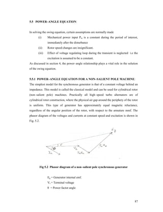
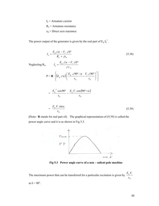
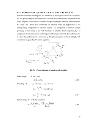
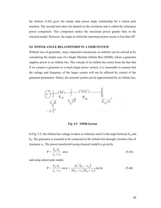
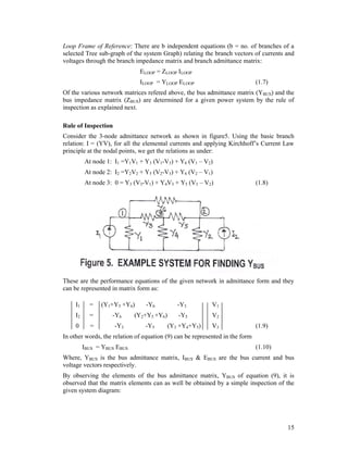
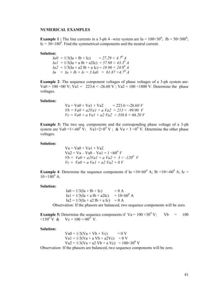
This document provides an overview of power system analysis and stability course content. The course will cover various topics related to power system modeling, analysis, and operation including representation of power systems using one-line diagrams and impedance diagrams, symmetrical and unsymmetrical fault analysis using symmetrical components, and system stability studies. The course will be taught over 35 hours by three subject experts in three weekly sessions, covering each of the five chapters in the textbook.

![CHAPTER 1
REPRESENTATION OF POWER SYSTEMS
[CONTENTS: One line diagram, impedance diagram, reactance diagram, per unit
quantities, per unit impedance diagram, formation of bus admittance &
impedance matrices, examples]
1.1 One Line Diagram
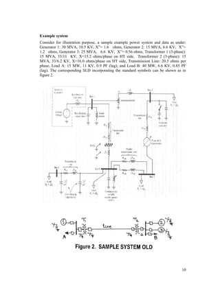
In practice, electric power systems are very complex and their size is unwieldy. It is very
difficult to represent all the components of the system on a single frame. The
complexities could be in terms of various types of protective devices, machines
(transformers, generators, motors, etc.), their connections (star, delta, etc.), etc. Hence,
for the purpose of power system analysis, a simple single phase equivalent circuit is
developed called, the one line diagram (OLD) or the single line diagram (SLD). An SLD
is thus, the concise form of representing a given power system. It is to be noted that a
given SLD will contain only such data that are relevant to the system analysis/study
under consideration. For example, the details of protective devices need not be shown for
load flow analysis nor it is necessary to show the details of shunt values for stability
studies.
Symbols used for SLD
Various symbols are used to represent the different parameters and machines as single
phase equivalents on the SLD,. Some of the important symbols used are as listed in the
table of Figure 1.
9](https://image.slidesharecdn.com/unit1-8-140301074701-phpapp01/85/Unit1-8-9-320.jpg)
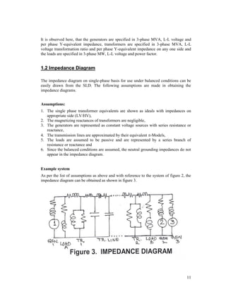
![In an electrical power system, the parameters of interest include the current, voltage,
complex power (VA), impedance and the phase angle. Of these, the phase angle is
dimensionless and the other four quantities can be described by knowing any two of
them. Thus clearly, an arbitrary choice of any two base values will evidently fix the other
base values.
Normally the nominal voltage of lines and equipment is known along with the complex
power rating in MVA. Hence, in practice, the base values are chosen for complex power
(MVA) and line voltage (KV). The chosen base MVA is the same for all the parts of the
system. However, the base voltage is chosen with reference to a particular section of the
system and the other base voltages (with reference to the other sections of the systems,
these sections caused by the presence of the transformers) are then related to the chosen
one by the turns-ratio of the connecting transformer.
If Ib is the base current in kilo amperes and Vb, the base voltage in kilovolts, then the base
MVA is, Sb = (VbIb). Then the base values of current & impedance are given by
Base current (kA), Ib = MVAb/KVb
= Sb/Vb
(1.1)
Base impedance, Zb = (Vb/Ib)
= (KVb2 / MVAb)
(1.2)
Hence the per unit impedance is given by
Zpu = Zohms/Zb
= Zohms (MVAb/KVb2)
(1.3)
In 3-phase systems, KVb is the line-to-line value & MVAb is the 3-phase MVA. [1-phase
MVA = (1/3) 3-phase MVA].
Changing the base of a given pu value:
It is observed from equation (3) that the pu value of impedance is proportional directly to
the base MVA and inversely to the square of the base KV. If Zpunew is the pu impedance
required to be calculated on a new set of base values: MVAbnew & KVbnew from the
already given per unit impedance Zpuold, specified on the old set of base values,
MVAbold & KVbold , then we have
Zpunew = Zpuold (MVAbnew/MVAbold) (KVbold/KVbnew)2
(1.4)
On the other hand, the change of base can also be done by first converting the given pu
impedance to its ohmic value and then calculating its pu value on the new set of base
values.
Merits and Demerits of pu System
Following are the advantages and disadvantages of adopting the pu system of
computations in electric power systems:
Merits:
13](https://image.slidesharecdn.com/unit1-8-140301074701-phpapp01/85/Unit1-8-13-320.jpg)
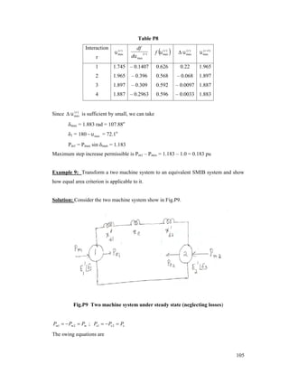
![1.8 Exercises for Practice
Problems
1. Determine the reactances of the three generators rated as follows on a common base of
200 MVA, 35 KV: Generator 1: 100 MVA, 33 KV, sub transient reactance of 10%;
Generator 2: 150 MVA, 32 KV, sub transient reactance of 8% and Generator 3: 110
MVA, 30 KV, sub transient reactance of 12%.
[Answers: XG1 = j 0.1778, Xg2 = j 0.089, Xg3 = j 0.16 all in per unit]
2. A 100 MVA, 33 KV, 3-phase generator has a sub transient reactance of 15%. The
generator supplies 3 motors through a step-up transformer - transmission line – stepdown transformer arrangement. The motors have rated inputs of 30 MVA, 20 MVA and
50 MVA, at 30 KV with 20% sub transient reactance each. The 3-phase transformers are
rated at 100 MVA, 32 KV- /110 KV-Y with 8 % leakage reactance. The line has a
reactance of 50 ohms. By selecting the generator ratings as base values in the generator
circuit, determine the base values in all the other parts of the system. Hence evaluate the
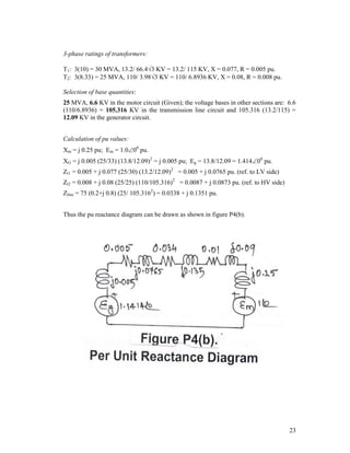
corresponding pu values and draw the equivalent per unit reactance diagram.
[Answers: XG = j 0.15, Xm1 = j 0.551, Xm2 = j 0.826, Xm3 = j 0.331, Eg1=1.0 00, Em1 = Em2
= Em3 = 0.9100, Xt1 = Xt2 = j 0.0775 and Xline = j 0.39 all in per unit]
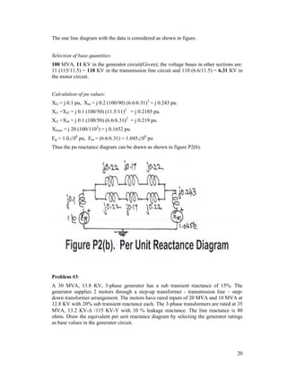
3. A 80 MVA, 10 KV, 3-phase generator has a sub transient reactance of 10%. The
generator supplies a motor through a step-up transformer - transmission line – step-down
transformer arrangement. The motor has rated input of 95 MVA, 6.3 KV with 15% sub
transient reactance. The step-up 3-phase transformer is rated at 90 MVA, 11 KV-Y /110
KV-Y with 10% leakage reactance. The 3-phase step-down transformer consists of three
single phase Y- connected transformers, each rated at 33.33 MVA, 68/6.6 KV with 10%
leakage reactance. The line has a reactance of 20 ohms. By selecting the 11 KV, 100
MVA as base values in the generator circuit, determine the base values in all the other
parts of the system. Hence evaluate the corresponding pu values and draw the equivalent
per unit reactance diagram.
[Answers:
XG = j 1.103, Xm = j 0.165, Eg1=0.9100, Em= 1.02200, Xt1 = j 0.11, Xt2 = j
0.114 and Xline = j 0.17 all in per unit]
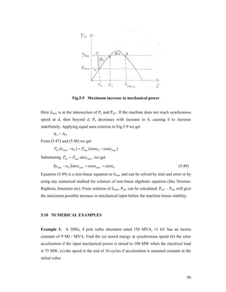
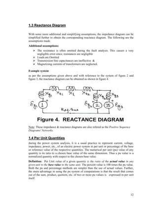
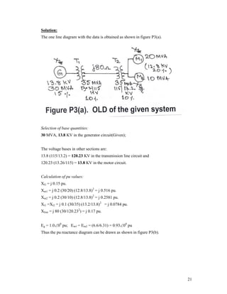
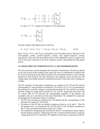
4. For the three-phase system shown below, draw an impedance diagram expressing all
impedances in per unit on a common base of 20 MVA, 2600 V on the HV side of the
transformer. Using this impedance diagram, find the HV and LV currents.
24](https://image.slidesharecdn.com/unit1-8-140301074701-phpapp01/85/Unit1-8-24-320.jpg)
![[Answers: Sb = 20 MVA; Vb=2.6 KV (HV) and 0.2427 KV (LV); Vt=1.000, Xt = j 0.107,
Zcable = 0.136 +j 0.204 and Zload = 5.66 + j 2.26, I = 0.158 all in per unit, I
(hv)= 0.7 A and I (lv) = 7.5 A]
Objective type questions
1. Under no load conditions the current in a transmission line is due to.
a) Corona effects
b) Capacitance of the line
c) Back flow from earth
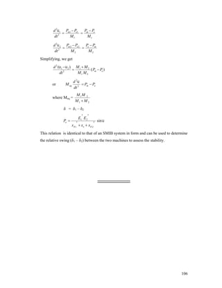
d) None of the above
2. In the short transmission line which of the following is used?
a) - Model
b) T – Model
c) Both (a) and (b)
d) None of the above
3. In the short transmission line which of the following is neglected?
a) I2 R loss
b) Shunt admittance
c) Series impedance
d) All of the above
4. Which of the following loss in a transformer is zero even at full load?
a) Eddy current
b) Hysteresis
c) Core loss
d) Friction loss
5. The transmission line conductors are transposed to
a) Balance the current
b) Obtain different losses
c) Obtain same line drops
d) Balance the voltage
[Ans.: 1(b), 2(a), 3(b), 4(d), 5(c)]
25](https://image.slidesharecdn.com/unit1-8-140301074701-phpapp01/85/Unit1-8-25-320.jpg)
![CHAPTER 2
SYMMETRICAL THREE PHASE FAULTS
[CONTENTS: Preamble, transients on a transmission line, short circuit of an unloaded
synchronous machine- short circuit currents and reactances, short circuit of a loaded
machine, selection of circuit breaker ratings, examples]
2.1 Preamble
in practice, any disturbance in the normal working conditions is termed as a FAULT. The
effect of fault is to load the device electrically by many times greater than its normal
rating and thus damage the equipment involved. Hence all the equipment in the fault line
should be protected from being overloaded. In general, overloading involves the increase
of current up to 10-15 times the rated value. In a few cases, like the opening or closing of
a circuit breaker, the transient voltages also may overload the equipment and damage
them.
In order to protect the equipment during faults, fast acting circuit breakers are put in the
lines. To design the rating of these circuit breakers or an auxiliary device, the fault
current has to be predicted. By considering the equivalent per unit reactance diagrams,
the various faults can be analyzed to determine the fault parameters. This helps in the
protection and maintenance of the equipment.
Faults can be symmetrical or unsymmetrical faults. In symmetrical faults, the fault
quantity rises to several times the rated value equally in all the three phases. For example,
a 3-phase fault - a dead short circuit of all the three lines not involving the ground. On the
other hand, the unsymmetrical faults may have the connected fault quantities in a random
way. However, such unsymmetrical faults can be analyzed by using the Symmetrical
Components. Further, the neutrals of the machines and equipment may or may not be
grounded or the fault may occur through fault impedance. The three-phase fault involving
ground is the most severe fault among the various faults encountered in electric power
systems.
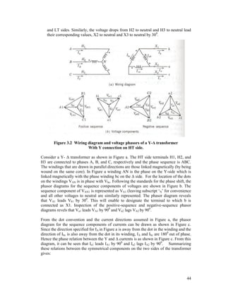
2.2 Transients on a transmission line
Now, let us Consider a transmission line of resistance R and inductance L supplied by an
ac source of voltage v, such that v = Vm sin (t+) as shown in figure 1. Consider the
short circuit transient on this transmission line. In order to analyze this symmetrical 3phase fault, the following assumptions are made:
The supply is a constant voltage source,
The short circuit occurs when the line is unloaded and
26](https://image.slidesharecdn.com/unit1-8-140301074701-phpapp01/85/Unit1-8-26-320.jpg)
![ The line capacitance is negligible.
Figure 1. Short Circuit Transients on an Unloaded Line.
Thus the line can be modeled by a lumped R-L series circuit. Let the short circuit take
place at t=0. The parameter, controls the instant of short circuit on the voltage wave.
From basic circuit theory, it is observed that the current after short circuit is composed of
the two parts as under: i =is +it, Where, is is the steady state current and it is the transient
current. These component currents are determined as follows.
Consider,
v = Vm sin (t+)
= iR + L (di/dt)
(2.1)
and
i = Im sin (t+-)
(22.)
Where
Vm = 2V; Im = 2I; Zmag = [R +(L) ]= tan (L/R)
(2.3)
Thus
is = [Vm/Z] sin (t+-)
(2.4)
2
2
-1
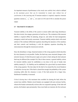
Consider the performance equation of the circuit of figure 1 under circuit as:
iR + L (di/dt) = 0
i.e.,
(R/L + d/dt)i = 0
(2.5)
In order to solve the equation (5), consider the complementary function part of the
solution as: CF = C1 e(-t/)
(2.6)
Where (= L/R) is the time constant and C1 is a constant given by the value of steady
state current at t = 0. Thus we have,
C1 = -is(0)
= - [Vm/Z] sin (-)
= [Vm/Z] sin (-)
(2.7)
Similarly the expression for the transient part is given by:
it = -is(0) e(-t/)
= [Vm/Z] sin (-) e(-R/L)t
(2.8)
Thus the total current under short circuit is given by the solution of equation (1) as
[combining equations (4) and (8)],
27](https://image.slidesharecdn.com/unit1-8-140301074701-phpapp01/85/Unit1-8-27-320.jpg)
![i =is +it
= [2V/Z] sin (t+-) + [2V/Z] sin (-) e(-R/L)t
(2.9)
Thus, is is the sinusoidal steady state current called as the symmetrical short circuit
current and it is the unidirectional value called as the DC off-set current. This causes the
total current to be unsymmetrical till the transient decays, as clearly shown in figure 2.
Figure 2. Plot of Symmetrical short circuit current, i(t).
The maximum momentary current, imm thus corresponds to the first peak. Hence, if the
decay in the transient current during this short interval of time is neglected, then we have
(sum of the two peak values);
imm = [2V/Z] sin (-) + [2V/Z]
(2.10)
now, since the resistance of the transmission line is very small, the impedance angle ,
can be taken to be approximately equal to 900. Hence, we have
imm = [2V/Z] cos + [2V/Z]
(2.11)
28](https://image.slidesharecdn.com/unit1-8-140301074701-phpapp01/85/Unit1-8-28-320.jpg)
![This value is maximum when the value of is equal to zero. This value corresponds to
the short circuiting instant of the voltage wave when it is passing through zero. Thus the
final expression for the maximum momentary current is obtained as:
imm = 2 [2V/Z]
(2.12)
Thus it is observed that the maximum momentary current is twice the maximum value of
symmetrical short circuit current. This is refered as the doubling effect of the short circuit
current during the symmetrical fault on a transmission line.
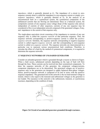
2.3 Short circuit of an unloaded synchronous machine
2.3.1 Short Circuit Reactances
Under steady state short circuit conditions, the armature reaction in synchronous
generator produces a demagnetizing effect. This effect can be modeled as a reactance, Xa
in series with the induced emf and the leakage reactance, Xl of the machine as shown in
figure 3. Thus the equivalent reactance is given by:
Xd = Xa +Xl
(2.13)
Where Xd is called as the direct axis synchronous reactance of the synchronous machine.
Consider now a sudden three-phase short circuit of the synchronous generator on no-load.
The machine experiences a transient in all the 3 phases, finally ending up in steady state
conditions.
Figure 3. Steady State Short Circuit Model
Immediately after the short circuit, the symmetrical short circuit current is limited only by
the leakage reactance of the machine. However, to encounter the demagnetization of the
armature short circuit current, current appears in field and damper windings, assisting the
rotor field winding to sustain the air-gap flux. Thus during the initial part of the short
circuit, there is mutual coupling between stator, rotor and damper windings and hence the
corresponding equivalent circuit would be as shown in figure 4. Thus the equivalent
reactance is given by:
Xd” = Xl +[1/Xa + 1/Xf + 1/Xdw]-1
(2.14)
29](https://image.slidesharecdn.com/unit1-8-140301074701-phpapp01/85/Unit1-8-29-320.jpg)
![Where Xd” is called as the sub-transient reactance of the synchronous machine. Here, the
equivalent resistance of the damper winding is more than that of the rotor field winding.
Hence, the time constant of the damper field winding is smaller. Thus the damper field
effects and the eddy currents disappear after a few cycles.
Figure 4. Model during Sub-transient Period of Short Circuit
In other words, Xdw gets open circuited from the model of Figure 5 to yield the model as
shown in figure 4. Thus the equivalent reactance is given by:
Xd’ = Xl +[1/Xa + 1/Xf ]-1
(2.15)
Where Xd’ is called as the transient reactance of the synchronous machine.
Subsequently, Xf also gets open circuited depending on the field winding time constant
and yields back the steady state model of figure 3.
Figure 5. Model during transient Period of Short Circuit
Thus the machine offers a time varying reactance during short circuit and this value of
reactance varies from initial stage to final one such that: Xd Xd’ Xd’
2.3.2 Short Circuit Current Oscillogram
Consider the oscillogram of short circuit current of a synchronous machine upon the
occurrence of a fault as shown in figure 6. The symmetrical short circuit current can be
divided into three zones: the initial sub transient period, the middle transient period and
finally the steady state period. The corresponding reactances, Xd,” Xd’ and Xd
respectively, are offered by the synchronous machine during these time periods.
30](https://image.slidesharecdn.com/unit1-8-140301074701-phpapp01/85/Unit1-8-30-320.jpg)
![Figure 6. SC current Oscillogram of Armature Current.
The currents and reactances during the three zones of period are related as under in terms
of the intercepts on the oscillogram (oa, ob and oc are the y-intercepts as indicated in
figure 6):
RMS value of the steady state current = I = [oa/2] = [Eg/Xd]
RMS value of the transient current = I’ = [ob/2] = [Eg/Xd’]
RMS value of the sub transient current = I = [oc/2] = [Eg/Xd”]
(2.16)
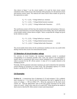
2.4 short circuit of a loaded machine
In the analysis of section 2.3 above, it has been assumed that the machine operates at no
load prior to the occurrence of the fault. On similar lines, the analysis of the fault
occurring on a loaded machine can also be considered.
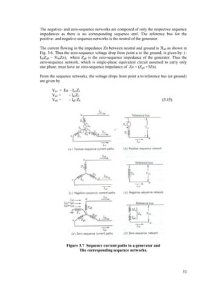
Figure 7 gives the circuit model of a synchronous generator operating under steady state
conditions supplying a load current Il to the bus at a terminal voltage Vt. Eg is the induced
emf under the loaded conditions and Xd is the direct axis synchronous reactance of the
generator.
Figure 7. Circuit models for a fault on a loaded machine.
31](https://image.slidesharecdn.com/unit1-8-140301074701-phpapp01/85/Unit1-8-31-320.jpg)
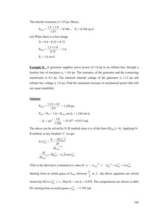
![Solution:
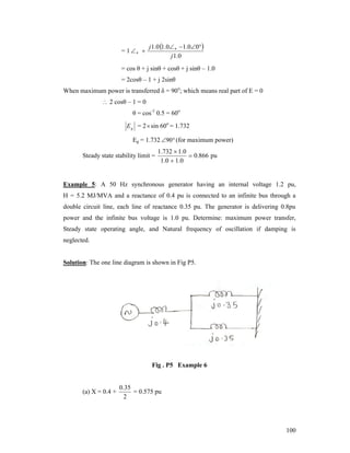
Figure P1.
Consider the expression for voltage applied to the transmission system given by
v = Vm sin(t+) = 100 sin (100t+150)
Thus we get: Vm = 100 volts; f = 50 Hz and
= 150.
Consider the impedance of the circuit given by:
Z = R + jL = 5 + j (100) (0.1) = 5 + j 31.416 ohms.
Thus we have: Zmag=31.8113 Ohms; =80.9570 and =L/R=0.1/5=0.02 seconds.
The short circuit current is given by:
i(t) = [Vm/Z] sin (t+-) + [Vm/Z] sin (-) e-(R/L)t
= [100/31.8113] [sin (100t+150-80.9570) + sin(80.9570-150) e-(t/0.02)]
= 3.1435 sin(314.16 t – 65.96) +2.871 e–50t
Thus we have:
i) imm = 3.1435 + 2.871 e–50t
where t is the time instant of maximum of symmetrical short circuit current. This instant
occurs at (314.16 tc – 65.960) = 900 ; Solving we get, t = 0.00867 seconds so that imm = 5
Amps.
ii) imm = 2Vm/Z = 6.287 A; for =0, and =900 (Also, imm = 2 (3.1435) = 6.287 A)
iii) DC offset current = [Vm/Z] sin (-) e-(R/L)t
= zero, if (-) = zero, i.e., = ,
or
= maximum if (-) = 900, i.e., = - 900, or
= 80.9570
= - 9.0430.
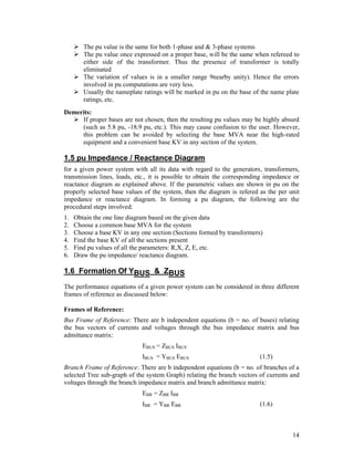
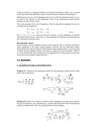
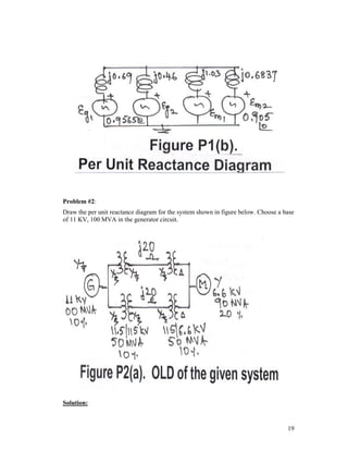
Problem #2: A 25 MVA, 11 KV, 20% generator is connected through a step-up
transformer- T1 (25 MVA, 11/66 KV, 10%), transmission line (15% reactance on a base
of 25 MVA, 66 KV) and step-down transformer-T2 (25 MVA, 66/6.6 KV, 10%) to a bus
that supplies 3 identical motors in parallel (all motors rated: 5 MVA, 6.6 KV, 25%). A
circuit breaker-A is used near the primary of the transformer T1 and breaker-B is used
near the motor M3. Find the symmetrical currents to be interrupted by circuit breakers A
and B for a fault at a point P, near the circuit breaker B.
33](https://image.slidesharecdn.com/unit1-8-140301074701-phpapp01/85/Unit1-8-33-320.jpg)
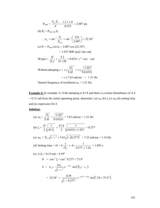
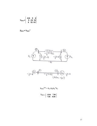
![Solution:
Consider the SLD with the data given in the problem statement. The base values are
selected as under:
Figure P2(a)
Selection of bases:
Sb = 25 MVA (common); Vb = 11 KV (Gen. circuit)- chosen so that then Vb = 66 KV
(line circuit) and Vb = 6.6 KV (Motor circuit).
Pu values:
Xg=j0.2 pu, Xt1=Xt2=j0.1 pu; Xm1=Xm2=Xm3=j0.25(25/5)=j1.25 pu; Xline=j0.15 pu.
Since the system is operating at no load, all the voltages before fault are 1 pu.
Considering the pu reactance diagram with the faults at P, we have:
Figure P2(b)
Current to be interrupted by circuit breaker A = 1.0 /j[0.2+0.1+0.15+0.1]
= - j 1.818 pu = - j 1.818 (25/[3(11)]) = - j 1.818 (1.312) KA = 2.386 KA
And Current to be interrupted by breaker B = 1/j1.25 = - j 0.8 pu
= - j0.8 (25/[3(6.6)]) = - j0.8 (2.187) KA = 1.75 KA.
34](https://image.slidesharecdn.com/unit1-8-140301074701-phpapp01/85/Unit1-8-34-320.jpg)
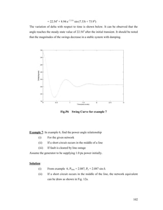
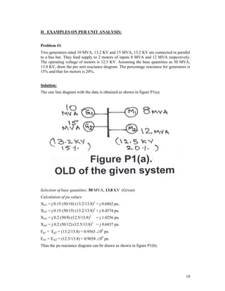
![Problem #3: Two synchronous motors are connected to a large system bus through a
short line. The ratings of the various components are: Motors(each)= 1 MVA, 440 volts,
0.1 pu reactance; line of 0.05 ohm reactance and the short circuit MVA at the bus of the
large system is 8 at 440 volts. Calculate the symmetrical short circuit current fed into a
three-phase fault at the motor bus when the motors are operating at 400 volts.
Solution:
Consider the SLD with the data given in the problem statement. The base values are
selected as under:
Figure P3.
Sb = 1 MVA; Vb = 0.44 KV (common)- chosen so that Xm(each)=j0.1 pu, Em = 1.000,
Xline=j0.05 (1/0.442) = j 0.258 pu and Xlarge-system -= (1/8) = j 0.125 pu.
Thus the prefault voltage at the motor bus; Vt = 0.4/0.44 = 0.90900,
Short circuit current fed to the fault at motor bus (If = YV);
If = [0.125 + 0.258]-1 + 2.0 }0.909 = [20.55 pu] [1000/(3(0.4))]
= 20.55 (1.312) KA = 26.966 KA.
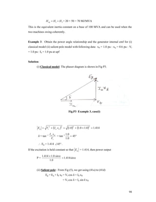
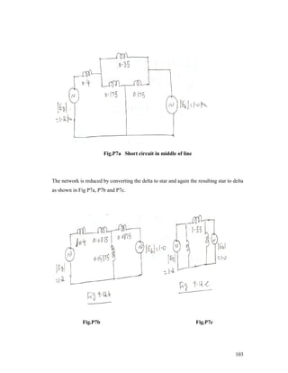
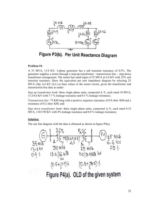
Problem #4: A generator-transformer unit is connected to a line through a circuit
breaker. The unit ratings are: Gen.: 10 MVA, 6.6 KV, Xd” = 0.1 pu, Xd’ = 0.2 pu and Xd
= 0.8 pu; and Transformer: 10 MVA, 6.9/33 KV, Xl = 0.08 pu; The system is operating
on no-load at a line voltage of 30 KV, when a three-phase fault occurs on the line just
beyond the circuit breaker. Determine the following:
(i) Initial symmetrical RMS current in the breaker,
(ii) Maximum possible DC off-set current in the breaker,
(iii) Momentary current rating of the breaker,
(iv) Current to be interrupted by the breaker and the interrupting KVA and
(v) Sustained short circuit current in the breaker.
Solution:
35](https://image.slidesharecdn.com/unit1-8-140301074701-phpapp01/85/Unit1-8-35-320.jpg)
![Consider the base values selected as 10 MVA, 6.6 KV (in the generator circuit) and
6.6(33/6.9) = 31.56 KV(in the transformer circuit). Thus the base current is:
Ib = 10 / [3(31.56)] = 0.183 KA
The pu values are: Xd” = 0.1 pu, Xd’ = 0.2 pu and Xd = 0.8 pu; and XTr = 0.08 (6.9/6.6)2
= 0.0874 pu; Vt = (30/31.6) = 0.9500 pu.
Initial symmetrical RMS current = 0.9500 / [0.1 + 0.0874] = 5.069 pu = 0.9277 KA;
Maximum possible DC off-set current = 2 (0.9277) = 1.312 KA;
Momentary current rating = 1.6(0.9277) = 1.4843 KA; (assuming 60% allowance)
Current to be interrupted by the breaker (5 Cycles) = 1.1(0.9277) = 1.0205 KA;
Interrupting MVA = 3(30) (1.0205) = 53.03 MVA;
Sustained short circuit current in the breaker = 0.9500 (0.183) / [0.8 + 0.0874]
= 0.1959 KA.
2.7 Exercises for Practice
PROBLEMS
1. The one line diagram for a radial system network consists of two generators, rated 10
MVA, 15% and 10 MVA, 12.5 % respectively and connected in parallel to a bus bar A at
11 KV. Supply from bus A is fed to bus B (at 33 KV) through a transformer T 1 (rated: 10
MVA, 10%) and OH line (30 KM long). A transformer T2 (rated: 5 MVA, 8%) is used in
between bus B (at 33 KV) and bus C (at 6.6 KV). The length of cable running from the
bus C up to the point of fault, F is 3 KM. Determine the current and line voltage at 11 kV
bus A under fault conditions, when a fault occurs at the point F, given that Zcable = 0.135
+ j 0.08 ohm/ kM and ZOH-line = 0.27 + j 0.36 ohm/kM.
[Answer: 9.62 kV at the 11 kV
bus]
2. A generator (rated: 25MVA, 12. KV, 10%) supplies power to a motor (rated: 20 MVA,
3.8 KV, 10%) through a step-up transformer (rated:25 MVA, 11/33 KV, 8%),
transmission line (of reactance 20 ohms) and a step-down transformer (rated:20 MVA,
33/3.3 KV, 10%). Write the pu reactance diagram. The system is loaded such that the
motor is drawing 15 MW at 0.9 leading power factor, the motor terminal voltage being
3.1 KV. Find the sub-transient current in the generator and motor for a fault at the
generator bus.
[Answer: Ig” = 9.337 KA; Im” = 6.9 KA]
3. A synchronous generator feeds bus 1 and a power network feed bus 2 of a system.
Buses 1 and 2 are connected through a transformer and a line. Per unit reactances of the
components are: Generator(bus-1):0.25; Transformer:0.12 and Line:0.28. The power
network is represented by a generator with an unknown reactance in series. With the
generator on no-load and with 1.0 pu voltage at each bus, a three phase fault occurring on
bus-1 causes a current of 5 pu to flow into the fault. Determine the equivalent reactance
of the power network.
[Answer: X = 0.6 pu]
4. A synchronous generateor, rated 500 KVA, 440 Volts, 0.1 pu sub-transient reactance is
supplying a passive load of 400 KW, at 0.8 power factor (lag). Calculate the initial
symmetrical RMS current for a three-phase fault at the generator terminals.
[Answer: Sb=0.5 MVA; Vb=0.44 KV; load=0.8–36.90; Ib=0.656 KA; If=6.97 KA]
36](https://image.slidesharecdn.com/unit1-8-140301074701-phpapp01/85/Unit1-8-36-320.jpg)
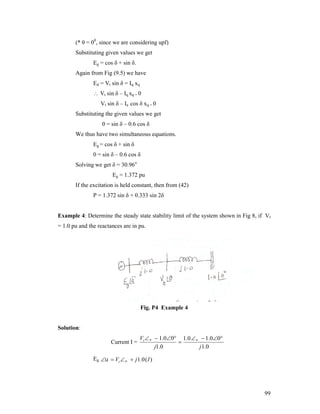
![OBJECTIVE TYPE QUESTIONS
1.
When a 1-phase supply is across a 1-phase winding, the nature of the
magnetic field produced is
a)
b)
Constant in magnitude and rotating at synchronous speed
c)
Pulsating in nature
d)
2.
Constant in magnitude and direction
Rotating in nature
The damper windings are used in alternators to
a)
b)
Reduce hunting
c)
Make rotor dynamically balanced
d)
3.
Reduce eddy current loss
Reduce armature reaction
The neutral path impedance Zn is used in the equivalent sequence network
models as
a)
b)
Zn
c)
3 Zn
d)
4.
Zn2
An ineffective value
An infinite bus-bar should maintain
a)
b)
Infinite frequency and Infinite voltage
c)
Constant frequency and Variable voltage
d)
5.
Constant frequency and Constant voltage
Variable frequency and Variable voltage
Voltages under extra high voltage are
a)
1KV & above
b)
11KV & above
c)
132 KV & above
d)
330 KV & above
[Ans.: 1(c), 2(b), 3(c), 4(a), 5(d)]
37](https://image.slidesharecdn.com/unit1-8-140301074701-phpapp01/85/Unit1-8-37-320.jpg)
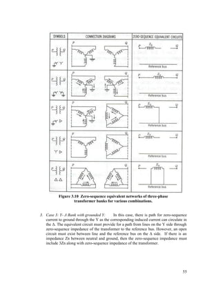
![CHAPTER 3: SYMMETRICAL COMPONENTS
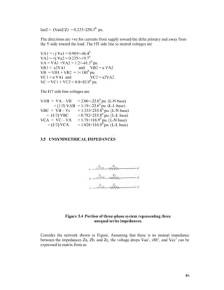
[CONTENTS: Introduction, The a operator, Power in terms of symmetrical components, Phase shift in YΔ transformer banks, Unsymmetrical series impedances, Sequence impedances, Sequence
networks, Sequence networks of an unloaded generator, Sequence networks of elements,
Sequence networks of power system]
3.1 INTRODUCTION
Power systems are large and complex three-phase systems. In the normal operating
conditions, these systems are in balanced condition and hence can be represented as an
equivalent single phase system. However, a fault can cause the system to become
unbalanced. Specifically, the unsymmetrical faults: open circuit, LG, LL, and LLG faults
cause the system to become unsymmetrical. The single-phase equivalent system method
of analysis (using SLD and the reactance diagram) cannot be applied to such
unsymmetrical systems. Now the question is how to analyze power systems under
unsymmetrical conditions? There are two methods available for such an analysis:
Kirchhoff’s laws method and Symmetrical components method.
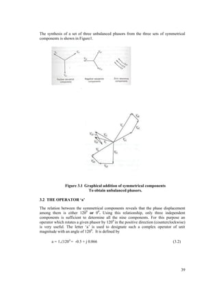
The method of symmetrical components developed by C.L. Fortescue in 1918 is a
powerful technique for analyzing unbalanced three phase systems. Fortescue defined a
linear transformation from phase components to a new set of components called
symmetrical components. This transformation represents an unbalanced three-phase
system by a set of three balanced three-phase systems. The symmetrical component
method is a modeling technique that permits systematic analysis and design of threephase systems. Decoupling a complex three-phase network into three simpler networks
reveals complicated phenomena in more simplistic terms.
Consider a set of three-phase unbalanced voltages designated as Va, Vb, and Vc.
According to Fortescue theorem, these phase voltages can be resolved into following
three sets of components.
1. Positive-sequence components, consisting of three phasors equal in magnitude,
displaced from each other by 1200 in phase, and having the same phase sequence as
the original phasors, designated as Va1, Vb1, and Vc1
2. Negative-sequence components, consisting of three phasors equal in magnitude,
displaced from each other by 1200 in phase, and having the phase sequence opposite
to that of the original phasors, designated as Va2, Vb2, and Vc2
3. Zero-sequence components, consisting of three phasors equal in magnitude, and with
zero phase displacement from each other, designated as Va0, Vb0, and Vc0
Since each of the original unbalanced phasors is the sum of its components, the
original phasors expressed in terns of their components are
Va = Va1 + Va2 + Va0
Vb = Vb1 + Vb2 + Vb0
Vc = Vc1 + Vc2 + Vc0
(3.1)
38](https://image.slidesharecdn.com/unit1-8-140301074701-phpapp01/85/Unit1-8-38-320.jpg)
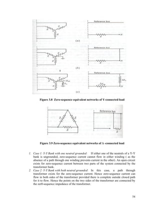
![Example 6: The line b of a 3-ph line feeding a balanced Y-load with neutral grounded is
open resulting in line currents: Ia = 10<00 A & Ic = 10<1200 A. Determine the sequence
current components.
Solution:
Ib = 0 A.
Ia0 = 1/3(Ia + Ib + Ic)
Ia1 = 1/3(Ia + a Ib + a2Ic)
Ia2 = 1/3(Ia + a2 Ib + a Ic)
= 3.33<600 A
= 6.66<00 A
= 3.33<-600 A
Example 7: One conductor of a 3-ph line feeding a balanced delta-load is open.
Assuming that line c is open, if current in line a is 10<00 A , determine the sequence
components of the line currents.
Solution:
Ic = 0 A; Ia = 10<00 A. Ib = 10<1200 A
Ia0 = 1/3(Ia + Ib + Ic)
= 0A
Ia1 = 1/3(Ia + a Ib + a2Ic) = 5.78<-300 A
Ia2 = 1/3(Ia + a2 Ib + a Ic) = 5.78< 300 A
Note: The zero-sequence components of line currents of a delta load (3-ph 3-wire) system
are zero.
3.3 POWER IN TERMS OF SYMMETRICAL COMPONENTS
The power in a three-phase system can be expressed in terms of symmetrical components
of the associated voltages and currents. The power flowing into a three-phase system
through three lines a, b and c is
S = P + j Q = Va Ia* + Vb Ib* + Vc Ic *
(3.9)
where Va , Vb and Vc are voltages to neutral at the terminals and Ia , Ib, and Ic are the
currents flowing into the system in the three lines. In matrix form
S va
vb
I a
v Ib
I c
c
*
Va
Vb
Vc
T
I a
I
b
I c
*
Thus
S = [A V]T [AI]*
Using the reversal rule of the matrix algebra
S = VT AT A* I*
Noting that AT = A and a and a 2 are conjugates,
42](https://image.slidesharecdn.com/unit1-8-140301074701-phpapp01/85/Unit1-8-42-320.jpg)
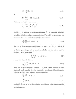
![CHAPTER 4: UNSYMMETRICAL FAULTS
[CONTENTS: Preamble, L-G, L-L, L-L-G and 3-phase faults on an unloaded alternator without and with
fault impedance, faults on a power system without and with fault impedance, open
conductor faults in power systems, examples]
4.1 PREAMBLE
The unsymmetrical faults will have faulty parameters at random. They can be analyzed
by using the symmetrical components. The standard types of unsymmetrical faults
considered for analysis include the following (in the order of their severity):
Line–to–Ground (L-G) Fault
Line–to–Line (L-L) Fault
Double Line–to–Ground (L-L-G)Fault and
Three-Phase–to–Ground (LLL-G) Fault.
Further the neutrals of various equipment may be grounded or isolated, the faults can
occur at any general point F of the given system, the faults can be through a fault
impedance, etc. Of the various types of faults as above, the 3- fault involving the ground
is the most severe one. Here the analysis is considered in two stages as under: (i) Fault at
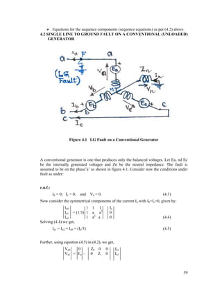
the terminals of a Conventional (Unloaded) Generator and (ii) Faults at any point F, of a
given Electric Power System (EPS).
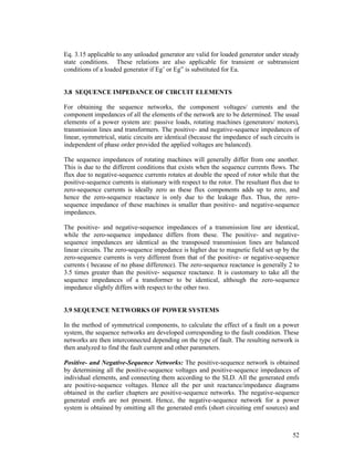
Consider now the symmetrical component relational equations derived from the three
sequence networks corresponding to a given unsymmetrical system as a function of
sequence impedances and the positive sequence voltage source in the form as under:
Va0 = - Ia0Z0
Va1 = Ea - Ia1Z1
Va2 = - Ia2Z2
(4.1)
These equations are refered as the sequence equations. In matrix Form the sequence
equations can be considered as:
Va0
0
Va1 = Ea –
Va2
0
Z0 0 0
0 Z1 0
0 0 Z2
Ia0
Ia1
Ia2
(4.2)
This equation is used along with the equations i.e., conditions under fault (c.u.f.), derived
to describe the fault under consideration, to determine the sequence current Ia1 and hence
the fault current If, in terms of Ea and the sequence impedances, Z1, Z2 and Z0. Thus
during unsymmetrical fault analysis of any given type of fault, two sets of equations as
follows are considered for solving them simultaneously to get the required fault
parameters:
Equations for the conditions under fault (c.u.f.)
58](https://image.slidesharecdn.com/unit1-8-140301074701-phpapp01/85/Unit1-8-58-320.jpg)
![Va2
0
0
0
Z2
Ia1
(4.6)
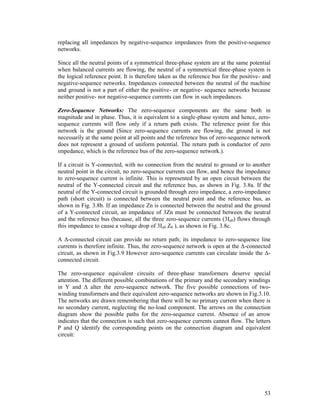
Pre-multiplying equation (4.6) throughout by [1 1 1], we get,
Va1+Va2+Va0 = - Ia1Z0 + Ea – Ia1Z1 – Ia2Z2
i.e.,
Va = Ea – Ia1 (Z1 + Z2 + Z0) = zero,
Or in other words,
Ia1 = [Ea/(Z1 + Z2 + Z0)]
(4.7)
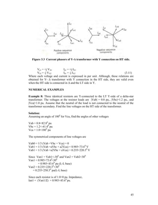
.
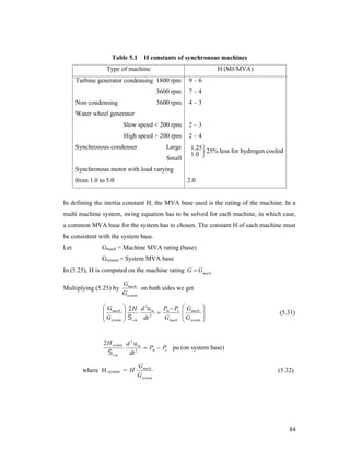
Figure 4.2 Connection of sequence networks for LG Fault
on phase a of a Conventional Generator
The equation (4.7) derived as above implies that the three sequence networks are
connected in series to simulate a LG fault, as shown in figure 4.2. Further we have the
following relations satisfied under the fault conditions:
1.
2.
3.
4.
5.
6.
7.
8.
9.
Ia1 = Ia2 = Ia0 = (Ia/3) = [Ea/(Z1 + Z2 + Z0)]
Fault current If = Ia = 3Ia1 = [3Ea/(Z1 + Z2 + Z0)]
Va1 = Ea - Ia1Z1 = Ea(Z2+Z0)/(Z1+Z2+Z0)
Va2 = - EaZ2/(Z1+Z2+Z0)
Va0 = - EaZ0/(Z1+Z2+Z0)
Fault phase voltage Va = 0,
Sound phase voltages Vb = a2Va1+aVa2+Va0; Vc = aVa1+a2Va2+Va0
Fault phase power: VaIa* = 0, Sound pahse powers: VbIb* = 0, and VcIc* = 0,
If Zn = 0, then Z0 = Zg0,
60](https://image.slidesharecdn.com/unit1-8-140301074701-phpapp01/85/Unit1-8-60-320.jpg)
![Solving (4.11) we get,
Ia0 = 0; and Ia2 = -Ia1
(4.12)
Using equation (4.10) and (4.12) in (4.2), and since Va0 = 0 ( Ia0 being 0), we get,
0
0
Z0 0 0
0
Va1 = Ea – 0 Z1 0
Ia1
Va1
0
0 0 Z2
-Ia1
Pre-multiplying equation (4.13) throughout by [0 1 -1], we get,
(4.13)
Va1-Va1 = Ea – Ia1Z1 – Ia1Z2 = 0
Or in other words,
Ia1 = [Ea/(Z1 + Z2)]
(4.14)
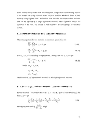
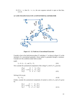
Figure 4.4 Connection of sequence networks for LL Fault
on phases b & c of a Conventional Generator
The equation (4.14) derived as above implies that the three sequence networks are
connected such that the zero sequence network is absent and only the positive and
negative sequence networks are connected in series-opposition to simulate the LL fault,
as shown in figure 4.4. Further we have the following relations satisfied under the fault
conditions:
1.
2.
3.
4.
5.
6.
7.
8.
9.
Ia1 = - Ia2 = [Ea/(Z1 + Z2)] and Ia0 = 0,
Fault current If = Ib = - Ic = [3Ea/(Z1 + Z2)] (since Ib = (a2-a)Ia1 = 3Ia1)
Va1 = Ea - Ia1Z1 = EaZ2/(Z1+Z2)
Va2 = Va1 = EaZ2/(Z1+Z2)
Va0 = 0,
Fault phase voltages;Vb = Vc = aVa1+a2Va2+Va0 = (a+a2)Va1 = - Va1
Sound phase voltage; Va = Va1+Va2+Va0 = 2Va1;
Fault phase powers are VbIb* and VcIc*,
Sound phase power: VaIa* = 0,
62](https://image.slidesharecdn.com/unit1-8-140301074701-phpapp01/85/Unit1-8-62-320.jpg)
![1/Z0
0
1/Z1
0
0
Z =
0
0
-1
0
1/Z2
(4.19)
We get,
-1
Z
Va1
0
Z0 0 0
-1
-1
Va1 = Z Ea – Z 0 Z1 0
Va1
0
0 0 Z2
Ia0
Ia1
Ia2
(4.20)
Using the identity: Va1= (Ea – Ia1Z1) in equation (4.19), pre-multiplying throughout by [1
1 1] and finally adding, we get,
Ea/Z0 - Ia1(Z1/Z0) + (Ea/Z1)- Ia1 + Ea/Z2 - Ia1(Z1/Z2) = (Ea/Z1) – (Ia0+Ia1+Ia2)
= (Ea/Z1) - Ia
= (Ea/Z1)
(4.21)
Since Ia = 0, solving the equation (4.21), we get,
Ia1 = { Ea/ [Z1 + Z2Z0/(Z2+Z0)] }
(4.22)
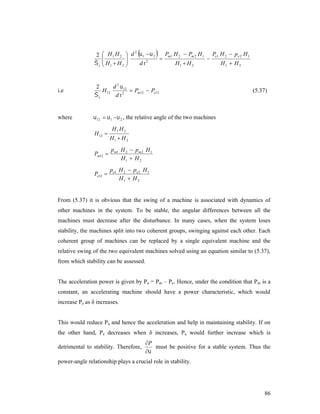
Figure4.6 Connection of sequence networks for LLG Fault on
phases b and c of a Conventional Generator
The equation (4.22) derived as above implies that, to simulate the LLG fault, the three
sequence networks are connected such that the positive network is connected in series
with the parallel combination of the negative and zero sequence networks, as shown in
figure 4.6. Further we have the following relations satisfied under the fault conditions:
1.
2.
3.
4.
5.
6.
Ia1 = {Ea/ [Z1+Z2Z0/(Z2+Z0)]}; Ia2= -Ia1Z0/(Z2 + Z0) and Ia0 = -Ia1Z2/(Z2 + Z0),
Fault current If: Ia0=(1/3)(Ia+Ib+Ic) = (1/3)(Ib+Ic) = If/3, Hence If = 3Ia0
Ia = 0, Vb=Vc=0 and hence Va1=Va2=Va0=Va/3
Fault phase voltages;Vb = Vc = 0
Sound phase voltage; Va = Va1+Va2+Va0 = 3Va1;
Fault phase powers are VbIb* = 0, and VcIc* = 0, since Vb=Vc=0
64](https://image.slidesharecdn.com/unit1-8-140301074701-phpapp01/85/Unit1-8-64-320.jpg)
![7. Healthy phase power: VaIa* = 0, since Ia=0
8. If Z0=, (i.e., the ground is isolated), then Ia0=0, and hence the result is the same
as that of the LL fault [with Z0=, equation (4.22) yields equation (4.14)].
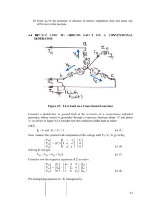
4.5
THREE PHASE
GENERATOR
TO
GROUND
FAULT
ON
A
CONVENTIONAL
Figure 4.7 Three phase ground Fault on a Conventional Generator
Consider a three phase to ground (LLLG) fault at the terminals of a conventional
unloaded generator, whose neutral is grounded through a reactance, between all its three
phases a, b and c, as shown in figure 4.7, Consider now the conditions under fault as
under:
c.u.f.:
Va = Vb = Vc = 0, Ia + Ib + Ic = 0
(4.23)
Now consider the symmetrical components of the voltage with Va=Vb=Vc= 0, given by:
Va0
Va1
Va2
1 1 1
= (1/3) 1 a a2
1 a2 a
0
0
0
(4.24)
65](https://image.slidesharecdn.com/unit1-8-140301074701-phpapp01/85/Unit1-8-65-320.jpg)
![Solving (4.24) we get,
Va1 = Va2 = Va0 = 0
(4.25)
Thus we have
Va1 = Ea1 – Ia1Z1
(4.26)
So that after solving for Ia1 we, get,
Ia1 = [ Ea / Z1 ]
(4.27)
Figure 4.8 Connection of sequence networks for 3-phase ground
Fault on phases b and c of a Conventional Generator
The equation (4.26) derived as above implies that, to simulate the 3-phase ground fault,
the three sequence networks are connected such that the negative and zero sequence
networks are absent and only the positive sequence network is present, as shown in figure
4.8. Further the fault current, If in case of a 3-phase ground fault is given by
If = Ia1= Ia = (Ea/Z1)
(4.28)
It is to be noted that the presence of a neutral connection without or with a neutral
impedance, Zn will not alter the simulated conditions in case of a three phase to ground
fault.
4.6 UNSYMMETRICAL FAULTS ON POWER SYSTEMS
In all the analysis so far, only the fault at the terminals of an unloaded generator have
been considered. However, faults can also occur at any part of the system and hence the
power system fault at any general point is also quite important. The analysis of
unsymmetrical fault on power systems is done in a similar way as that followed thus far
for the case of a fault at the terminals of a generator. Here, instead of the sequence
impedances of the generator, each and every element is to be replaced by their
corresponding sequence impedances and the fault is analyzed by suitably connecting
them together to arrive at the Thevenin equivalent impedance if that given sequence.
Also, the internal voltage of the generators of the equivalent circuit for the positive
66](https://image.slidesharecdn.com/unit1-8-140301074701-phpapp01/85/Unit1-8-66-320.jpg)
![sequence network is now Vf (and not Ea), the pre-fault voltage to neutral at the point of
fault (PoF) (ref. Figure 4.9).
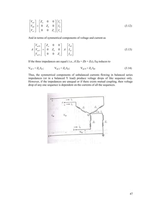
Figure 4.9 Unsymmetrical faults in Power Systems
Thus, for all the cases of unsymmetrical fault analysis considered above, the sequence
equations are to be changed as under so as to account for these changes:
Va0
0
Va1 = Vf –
Va2
0
Z0 0 0
0 Z1 0
0 0 Z2
Ia0
Ia1
Ia2
(i) LG Fault at any point F of a given Power system
Let phase ‘a’ be on fault at F so that then, the c.u.f. would be:
Ib = 0; Ic = 0; and Va = 0.
Hence the derived conditions under fault would be:
Ia1 = Ia2 = Ia0 = (Ia/3)
Ia1 = [Vf / (Z1 + Z2 + Z0)] and
If = 3Ia1
(4.29)
(4.30)
(ii) LL Fault at any point F of a given Power system
Let phases ‘b’ and ‘c’ be on fault at F so that then, the c.u.f. would be:
Ia = 0; Ib = - Ic; and Vb = Vc
Hence the derived conditions under fault would be:
Va1 = Va2; Ia0 = 0; Ia2 = -Ia1
Ia1 = [Vf / (Z1 + Z2)] and
If = Ib = - Ic = [3 Vf / (Z1 + Z2)]
(4.31)
(ii) LLG Fault at any point F of a given Power system
Let phases ‘b’ and ‘c’ be on fault at F so that then, the c.u.f. would be:
Ia = 0 and Vb = Vc = 0
Hence the derived conditions under fault would be:
Va1 = Va2 = Va0 = (Va/3)
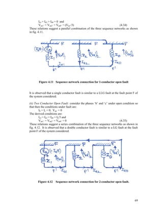
67](https://image.slidesharecdn.com/unit1-8-140301074701-phpapp01/85/Unit1-8-67-320.jpg)
![Ia1 = {Vf / [Z1+Z2Z0/(Z2+Z0)]}
Ia2= -Ia1Z0/(Z2 + Z2); Ia0 = -Ia1Z2/(Z2 + Z2) and
If = 3Ia0
(4.32)
(ii) Three Phase Fault at any point F of a given Power system
Let all the 3 phases a, b and c be on fault at F so that then, the c.u.f. would be:
Va = Vb = Vc = 0, Ia + Ib + Ic = 0
Hence the derived conditions under fault would be:
Va1 = Va2 = Va0 = Va/3
Va0 = Va1 = Va2 = 0; Ia0 = Ia2 = 0,
Ia1 = [Vf /Z1] and If = Ia1=Ia
(4.33)
4.7 OPEN CONDUCTOR FAULTS
Various types of power system faults occur in power systems such as the shunt type faults
(LG, LL, LLG, LLLG faults) and series type faults (open conductor and cross country
faults). While the symmetrical fault analysis is useful in determination of the rupturing
capacity of a given protective circuit breaker, the unsymmetrical fault analysis is useful in
the determination of relay setting, single phase switching and system stability studies.
When one or two of a three-phase circuit is open due to accidents, storms, etc., then
unbalance is created and the asymmetrical currents flow. Such types of faults that come
in series with the lines are refered as the open conductor faults. The open conductor faults
can be analyzed by using the sequence networks drawn for the system under
consideration as seen from the point of fault, F. These networks are then suitably
connected to simulate the given type of fault. The following are the cases required to be
analyzed (ref. fig.4.10).
Figure 4.10 Open conductor faults.
(i) Single Conductor Open Fault: consider the phase ‘a’ conductor open so that then the
conditions under fault are:
Ia = 0; Vbb’ = Vcc’ = 0
The derived conditions are:
68](https://image.slidesharecdn.com/unit1-8-140301074701-phpapp01/85/Unit1-8-68-320.jpg)
![(iii) Three Conductor Open Fault: consider all the three phases a, b and c, of a 3-phase
system conductors be open. The conditions under fault are:
Ia + Ib + Ic = 0
The derived conditions are:
Ia1 = Ia2 = Ia0 = 0 and
Va0 = Va2 = 0 and Va1 = Vf
(4.36)
These relations imply that the sequence networks are all open circuited. Hence, in a strict
analystical sense, this is not a fault at all!
4.8
FAULTS THROUGH IMPEDANCE
All the faults considered so far have comprised of a direct short circuit from one or two
lines to ground. The effect of impedance in the fault is found out by deriving equations
similar to those for faults through zero valued neutral impedance. The connections of the
hypothetical stubs for consideration of faults through fault impedance Zf are as shown in
figure 4.13.
Fig
ure 4.13
Stubs Connections for faults through fault impedance Zf.
(i) LG Fault at any point F of a given Power system through Zf
Let phase ‘a’ be on fault at F through Zf, so that then, the c.u.f. would be:
Ib = 0; Ic = 0; and Va = 0.
Hence the derived conditions under fault would be:
Ia1 = Ia2 = Ia0 = (Ia/3)
Ia1 = [Vf / (Z1 + Z2 + Z0+3Zf)] and
If = 3Ia1
(4.37)
(ii) LL Fault at any point F of a given Power system through Zf
Let phases ‘b’ and ‘c’ be on fault at F through Zf, so that then, the c.u.f. would be:
Ia = 0; Ib = - Ic; and Vb = Vc
Hence the derived conditions under fault would be:
Va1 = Va2; Ia0 = 0; Ia2 = -Ia1
Ia1 = [Vf / (Z1 + Z2+Zf)] and
If = Ib = - Ic = [3 Vf / (Z1 + Z2+Zf)]
(4.38)
(iii) LLG Fault at any point F of a given Power system through Zf
70](https://image.slidesharecdn.com/unit1-8-140301074701-phpapp01/85/Unit1-8-70-320.jpg)
![Let phases ‘b’ and ‘c’ be on fault at F through Zf,, so that then, the c.u.f. would be:
Ia = 0 and Vb = Vc = 0
Hence the derived conditions under fault would be:
Va1 = Va2 = Va0 = (Va/3)
Ia1 = {Vf / [Z1+Z2(Z0+3Zf)/(Z2+Z0+3Zf)]}
Ia2= -Ia1(Z0+3Zf)/(Z2+Z0+3Zf); Ia0 = -Ia1Z2/(Z2+(Z0+3Zf) and
If = 3Ia0
(4.39)
(iv) Three Phase Fault at any point F of a given Power system through Zf
Let all the 3 phases a, b and c be on fault at F, through Zf so that the c.u.f. would be: Va =
IaZf ; Hence the derived conditions under fault would be: Ia1 = [Vf /(Z1+Zf); The
connections of the sequence networks for all the above types of faults through Zf are as
shown in figure 4.14.
LG Fault
LLG Fault
LL Fault
3-Ph. Fault
71](https://image.slidesharecdn.com/unit1-8-140301074701-phpapp01/85/Unit1-8-71-320.jpg)
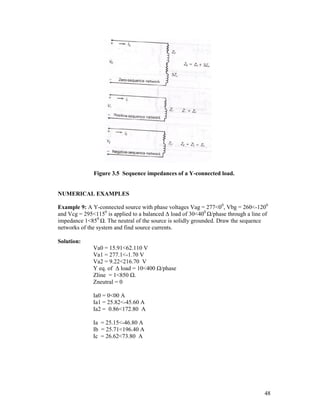
![Figure 4.15
4.9
Sequence network connections for faults through impedance
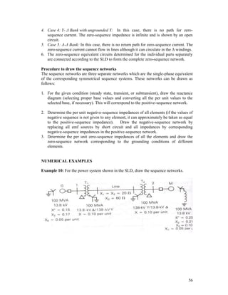
EXAMPLES
Example-1: A three phase generator with constant terminal voltages gives the following
currents when under fault: 1400 A for a line-to-line fault and 2200 A for a line-to-ground
fault. If the positive sequence generated voltage to neutral is 2 ohms, find the reactances
of the negative and zero sequence currents.
Solution: Case a) Consider the conditions w.r.t. the LL fault:
Ia1 = [Ea1/(Z1 + Z2)]
If = Ib = - Ic = 3 Ia1
=3 Ea1 / (Z1 + Z2) or
(Z1 + Z2) = 3 Ea1 / If
i.e., 2 + Z2 = 3 [2000/1400]
Solving, we get,
Z2 = 0.474 ohms.
Case b) Consider the conditions w.r.t. a LG fault:
Ia1 = [Ea1/(Z1 + Z2+Z0)]
If = 3 Ia1
= 3 Ea1 / (Z1 + Z2+Z0) or
(Z1 + Z2+Z0) = 3 Ea1 / If
i.e., 2 + 0.474 + Z0 = 3 [2000/2200]
Solving, we get,
Z0 = 0.253 ohms.
Example-2: A dead fault occurs on one conductor of a 3-conductor cable supplied y a 10
MVA alternator with earhed neutral. The alternator has +ve, -ve and 0-sequence
components of impedances per phase respectively as: (0.5+j4.7), (0.2+j0.6) and (j0.43)
ohms. The corresponding LN values for the cable up to the point of fault are:
(0.36+j0.25), (0.36+j0.25) and (2.9+j0.95) ohms respectively. If the generator voltage at
no load (Ea1) is 6600 volts between the lines, determine the (i)Fault current, (ii)Sequence
components of currents in lines and (iii)Voltages of healthy phases.
Solution: There is LG fault on any one of the conductors. Consider the LG fault to be on
conductor in phase a. Thus the fault current is given by:
(i) Fault current: If = 3Ia0 = [3Ea/(Z1 + Z2 + Z0)]
= 3(6600/3)/ (4.32+j7.18)
= 1364.24 58.970.
72](https://image.slidesharecdn.com/unit1-8-140301074701-phpapp01/85/Unit1-8-72-320.jpg)
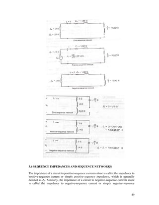
![(ii) Sequence components of line currents:
Ia1 = Ia2 = Ia0 = Ia/3 = If/3 = 454.75 58.970.
(iii) Sound phase voltages:
Va1 = Ea - Ia1Z1 = Ea(Z2+Z0)/(Z1+Z2+Z0) = 1871.83 -26.170,
Va2 = - EaZ2/(Z1+Z2+Z0) = 462.91 177.60,
Va0 = - EaZ0/(Z1+Z2+Z0) = 1460.54 146.50,
Thus,
Sound phase voltages Vb = a2Va1+aVa2+Va0 = 2638.73 -165.80 Volts,
And Vc = aVa1+a2Va2+Va0 = 3236.35 110.80 Volts.
Example-3: A generator rated 11 kV, 20 MVA has reactances of X1=15%, X2=10% and
X0=20%. Find the reactances in ohms that are required to limit the fault current to 2 p.u.
when a a line to ground fault occurs. Repeat the analysis for a LLG fault also for a fault
current of 2 pu.
Solution: Case a: Consider the fault current expression for LG fault given by:
If = 3 Ia0
i.e., 2.0 = 3Ea / j[X1+X2+X0]
= 3(1.000) / j[0.15+0.1+0.2+3Xn]
Solving we get
3Xn = 2.1 pu
= 2.1 (Zb) ohms = 2.1 (112/20) = 2.1(6.05)
= 12.715 ohms.
Thus
Xn = 4.235 ohms.
Case b: Consider the fault current expression for LLG fault given by:
If = 3Ia0 = 3 { -Ia1X2/(X2 + X0+3Xn)}= 2.0,
where, Ia1 = {Ea/ [X1+X2(X0+3Xn)/(X2+X0+3Xn)]}
Substituting and solving for Xn we get,
Xn = 0.078 pu
= 0.47 ohms.
Example-4: A three phase 50 MVA, 11 kV generator is subjected to the various faults
and the surrents so obtained in each fault are: 2000 A for a three phase fault; 1800 A for a
line-to-line fault and 2200 A for a line-to-ground fault. Find the sequence impedances of
the generator.
Solution: Case a) Consider the conditions w.r.t. the three phase fault:
If = Ia = Ia1 = Ea1/Z1
i.e., 2000 = 11000/ (3Z1)
Solving, we get,
Z1 = 3.18 ohms (1.3 pu, with Zb = (112/50) = 2.42 ohms).
73](https://image.slidesharecdn.com/unit1-8-140301074701-phpapp01/85/Unit1-8-73-320.jpg)
![Case b) Consider the conditions w.r.t. the LL fault:
Ia1 = [Ea1/(Z1 + Z2)]
If = Ib = - Ic = 3 Ia1
=3 Ea1 / (Z1 + Z2) or
(Z1 + Z2) = 3 Ea1 / If
i.e., 3.18 + Z2 = 3 (11000/3)/1800
Solving, we get,
Z2 = 2.936 ohms = 1.213 pu.
Case c) Consider the conditions w.r.t. a LG fault:
Ia1 = [Ea1/(Z1 + Z2+Z0)]
If = 3 Ia1
= 3 Ea1 / (Z1 + Z2+Z0) or
(Z1 + Z2+Z0) = 3 Ea1 / If
i.e., 3.18+ 2.936 + Z0 = 3 (11000/3)/ 2200
Solving, we get,
Z0 = 2.55 ohms = 1.054 pu.
74](https://image.slidesharecdn.com/unit1-8-140301074701-phpapp01/85/Unit1-8-74-320.jpg)