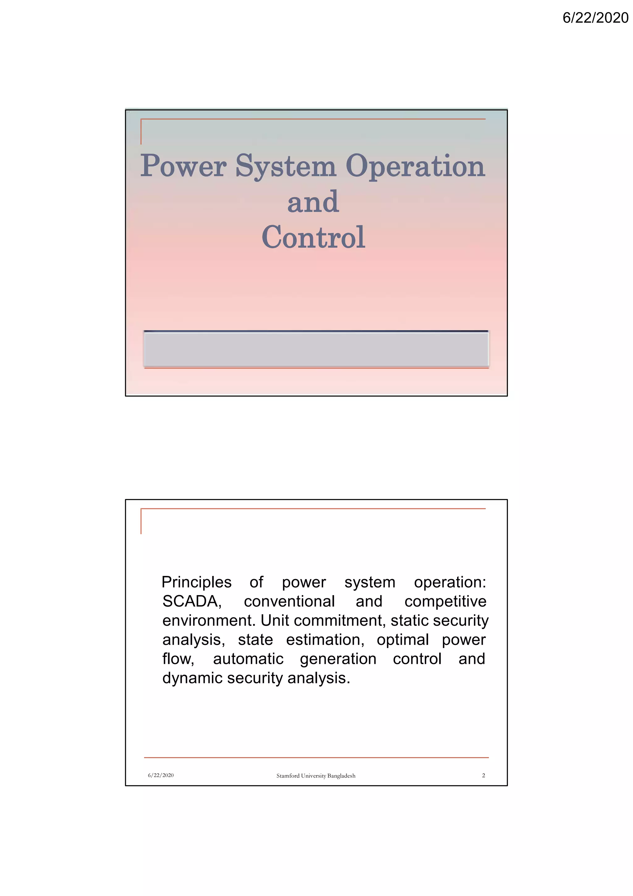
This document discusses a course on power system operation and control. It includes:
- An overview of principles like SCADA systems, unit commitment, and security analysis.
- A list of recommended textbooks and software like PowerWorld and Matlab.
- A description of the general structure of modern power systems including generation, transmission, distribution, and loads.
Power system operation & control( Switching & Controlling System)
1. 6/22/2020
Power System Operation
and
Control
6/22/2020 Stamford University Bangladesh 2
Principles of power system operation:
SCADA, conventional and competitive
environment. Unit commitment, static security
analysis, state estimation, optimal power
flow, automatic generation control and
dynamic security analysis.
2. 6/22/2020
Course Materials
Text Books
1. Power System Stability and Control-by P.
Kundur
2. Power System Analysis- by Hadi Saadat
Reference Books
1. Elements of Power Systems Analysis- by
William D. Stevenson, JR
2. Online[http://nptel.ac.in/downloads/1081010
40/]
6/22/2020 Stamford University Bangladesh 3
Course Materials
Power World Simulator
Matlab Simulink
6/22/2020 Stamford University Bangladesh 4
3. 6/22/2020
General Characteristics of
Modern Power System
Structure of Modern Power System
6/22/2020 Stamford University Bangladesh 5
A power system can be subdivided into four
major parts:
Generation
Transmission and Subtransmission
Distribution
Loads
Generation
Three phase ac generator known as synchronous
generator or alternator.
It can generate high power( 50MW to1500MW) at high
voltage upto 30kV
The source of mechanical power, commonly known as
the prime mover.
Steam turbines operate at relatively high speed of 3600
or 1800 rpm
Transmission
Transfer electric energy from generating units at various
locations to the distribution system.
Economic dispatch of power.
6/22/2020 Stamford University Bangladesh 6
4. 6/22/2020
Transmission
Transfer power between region during emergencies.
Subtransmission
The portion of the transmission system that connects the
high-voltage substations through step down transformer
to the distribution substation are called the
subtransmission network(69kV-138kV)
Loads
Industrial
Commercial
Residential
6/22/2020 Stamford University Bangladesh 7
Structure of power systems
6/22/2020 Stamford University Bangladesh 8
5. 6/22/2020
Power Systems Control
Fundamental Requirements of Sound Power
Systems
6/22/2020 Stamford University Bangladesh 9
Able to meet continually changing the load
demand for active and reactive power.
The system should supply energy at minimum
cost and with minimum ecological impact.
Power Systems Control
Fundamental Requirements of Sound Power
Systems
6/22/2020 Stamford University Bangladesh 10
The “quality” of power supply must meet
certain minimum standards with regards to
the following factors:
Constancy of frequency;
Constancy of voltage; and
Level of reliability
6. 6/22/2020
Subsystems of a power system
and associated control
6/22/2020 Stamford University Bangladesh 11
Subsystems of a power system
and associated control
Prime mover control
I. Speed regulation
II. Control of energy supply system( boiler
pressures, temperature, flows)
Excitation control
Regulate generatorvoltage
Reactive power output
6/22/2020 Stamford University Bangladesh 12
7. 6/22/2020
Subsystems of a power system
and associated control
System generation control (to balance
generation against system load and loss in
order maintain desired frequency with
neighbouring systems( tie flows).
Transmission control includes voltage and
power control devices such as; static vars
compensators, synchronous condensers,
switch capacitor and reactors, tap changing
transformer, phase shifting transformer.
6/22/2020 Stamford University Bangladesh 13
Operating State of a Power
System and Control Strategies
System operating condition can be classified
into five states;
Normal
Alert
Emergency
Extremis
Restorative
6/22/2020 Stamford University Bangladesh 14
8. 6/22/2020
Operating States of a Power
System
6/22/2020 Stamford University Bangladesh 15
Operating States of a Power
System
Normal State
Variables are within normal range
Able to withstand a contingency
Alert State
Possibility of disturbance increases of
adverse weather conditions.
All system variables are still within the
acceptable range.
6/22/2020 Stamford University Bangladesh 16
9. 6/22/2020
Operating States of a Power
System
Emergency
A contingency may cause an overloading of
equipment that places the system in an
emergency state.
In Extremis
If the disturbance is severe, the extremis
state may result directly from the alert
system.
Restorative
6/22/2020 Stamford University Bangladesh 17
Basic Concept and Definition
Preventive action, such as generation shifting
Power system operating constraint
There are two types of constraints which limit
the capability of power system.
Equipment constraint
Maximum current handling capability of a
conductor
Maximum voltage across an insulator before
it breaks down
6/22/2020 Stamford University Bangladesh 18
10. 6/22/2020
Basic Concept and Definition
Stability constraint
A power system may not be able to cater to
power flows beyond a certain point due to
stability constraints. An unstable system is a
one which cannot withstand disturbances,
i.e., it may not settle to an equilibrium
although a post-disturbance equilibrium
condition may exist.
6/22/2020 Stamford University Bangladesh 19
Basic Concept and Definition
There are two major equipment constraint
Thermal
Excessive heat produced by current carrying
conductors results in unacceptable sags in
transmission lines and degradation of
insulation in other equipment.
Dielectric
Over-voltages result in large electric fields
causing dielectric breakdown. Dielectric
breakdown may also occur due to aging or
6/22/2020 Stamford University Bangladesh 20
11. 6/22/2020
Basic Concept and Definition
degradation of insulation due to thermal limit
violations. Typically +/- 10% variation in the
rated voltage is often permissible.
Generator Limit
Voltage Limit
The terminal voltage of a generator is limited
due to 2 reasons : 1) Dielectric 2) Heating in
core due to excess magnetic flux. However,
the maximum continuous limit due to excess
flux is lower than that due to dielectric
6/22/2020 Stamford University Bangladesh 21
Basic Concept and Definition
breakdown consideration.
Armature Winding (heating) Limit
Winding heating results due to the resistive
loss in armature windings.
Field Winding (heating) Limit
Ohmic loss and consequent heating in the
field winding, imposes a restriction on the
maximum field current.
6/22/2020 Stamford University Bangladesh 22
12. 6/22/2020
Basic Concept and Definition
Core-end Heating Limit
Core-end heating results when field current is
low (under-excitation). During under
excitation conditions, the axial flux in the end
region is enhanced. This results in heating
which may limit the capability of a generator.
6/22/2020 Stamford University Bangladesh 23
Basic Concept and Definitions
Power System Stability
Power system stability may be broadly
defined as that property of a power system
that enables it to a remain in a state of a
operating equilibrium under normal operating
conditions and to regain an acceptable state
of equilibrium after being subjected to a
disturbance.
6/22/2020 Stamford University Bangladesh 24
13. 6/22/2020
Power System Stability
Usually power system stability is categorized
into Steady State, Transient and Dynamic Stability.
6/22/2020 Stamford University Bangladesh 25
Steady State
Stability studies are
restricted to small and
gradual changes in the
system operating conditions.
In this we basically
concentrate on restricting the
bus voltages close to their
nominal values. We also
ensure that phase angles
between two buses are not
Power System Stability
too large and check for the overloading of the power
equipment and transmission lines. These checks are
usually done using power flow studies.
Transient Stability involves the study of the power
system following a major disturbance. Following a large
disturbance the synchronous alternator the machine
power (load) angle changes due to sudden acceleration
of the rotor shaft. The objective of the transient stability
study is to ascertain whether the load angle returns to a
steady value following the clearance of the disturbance.
6/22/2020 Stamford University Bangladesh 26
14. 6/22/2020
Power System Stability
Dynamic Stability
The ability of a power system to maintain
stability under continuous small disturbances is
investigated under the name of Dynamic
Stability (also known as small-signal stability).
These small disturbances occur due random
fluctuations in loads and generation levels. In
an interconnected power system, these random
variations can lead catastrophic failure as this
may force the rotor angle to increase steadily.
6/22/2020 Stamford University Bangladesh 27
Power System Security
Difference between reliability and security
Reliability of a power system refers to the probability of satisfactory
operation over the long run. It denotes the ability to supply adequate
electric service on a nearly continuous basis, with few interruptions
over an extended time period. (IEEE Paper on Terms & Definitions,
2004)
Security is a time-varying attribute which can be judged by studying
the performance of the power system under a particular set of
conditions. Reliability, on the other hand, is a function of the time-
average performance of the power system; it can only be judged by
consideration of the system’s behaviour over an appreciable period of
time.
6/22/2020 Stamford University Bangladesh 28
15. 6/22/2020
Power System Security
6/22/2020 Stamford University Bangladesh 29
Contingency Analysis
6/22/2020 Stamford University Bangladesh 30
Generation outages:
The initial imbalance will result in frequency drop which must be
restored.
Other generators must make up the loss of power from the outaged
generator – must have sufficient spinning reserve.
Line flows and bus voltages will be altered – check for violations.
Transmission Outages:
All flows in nearby lines and bus voltages will be affected.
The result can be line flow limit and/or voltage limit violations.
Other outages:
Bus outages
Loss of load
17. 6/22/2020
Synchronous Generator Power and
Torque Equation
6/22/2020 Stamford University Bangladesh 33
Notice that the maximum
power that the generator
can supply occurs when δ
= 90° . At δ = 90°, sin δ =
I , and
the induced torque in this generator can be expressed as
Basic Concept and Definitions
Rotor Angle Stability
Rotor angle stability is the ability of the interconnected
synchronous machine of a power system to remain in
synchronism.
Power versus Angle Relationship
Two synchronous machine connected by a transmission
line having an inductive reactance XL but negligible
resistance and capacitance. Let us assume that machine
1 is a generator feeding power to a synchronous motor
represented by machine 2.
6/22/2020 Stamford University Bangladesh 34
18. 6/22/2020
Power versus Angle Relationship
Power transferred from generator to motor is
a function of angular separation between
rotors of the two machines.
6/22/2020 Stamford University Bangladesh 35
δ
Power versus Angle Relationship
The angular separation is due to the three
components;
Generator internal angle ( angle by which
generator rotor leads the revolving field of
stator.
Angular difference between terminal voltage
of generator and motor( angle by which stator
field of generator that of the motor).
Internal angle of the motor (angle by which
rotor lags the revolving stator field).
6/22/2020 Stamford University Bangladesh 36
19. 6/22/2020
Power versus Angle Relationship
Power transferred from generator to motor is
given by
where
When angle is zero no power is transferred.
As the angle is increased, power transfer
increases up to a maximum, a further
increase in angle results in a decrease in
power transferred.
6/22/2020 Stamford University Bangladesh 37
Power versus Angle Relationship
6/22/2020 Stamford University Bangladesh 38
Power angle curvePhasor diagram
20. 6/22/2020
Basic Concept and Definitions
Voltage Stability
Voltage stability is the ability of power system
to maintain steady acceptable voltages at all
buses in the system under normal operating
conditions after being subjected to a
disturbance.
6/22/2020 Stamford University Bangladesh 39
Voltage Stability and Voltage Collapse
The main factor causing instability is the inability of the power system to
meet the demand for reactive power. The heart of the problem is
usually the voltage drop that occurs when active power and reactive
power flow through inductive reactance associated with the
transmission network.
A criterion for voltage stability is that, at a given operating condition for
every bus in the system, the bus voltage magnitude (V) increases as
the reactive power injection at the same bus is increased. A system is
voltage unstable if, for at least one bus in the system, the bus voltage
magnitude (V) decreases as the reactive power injection (Q) at the
same bus is increased. In other words, a system is voltage stable if V-Q
sensitivity is positive for every bus and voltage unstable if V-Q
sensitivity is negative for at least one bus.
6/22/2020 Stamford University Bangladesh 40
21. 6/22/2020
Voltage Stability Analysis
6/22/2020 Stamford University Bangladesh 41
The expression for
current I for the following
network is
Let assume a constant voltage source Es supplying a load
ZLD through a series impedance ZLN.
Voltage Stability Analysis
6/22/2020 Stamford University Bangladesh 42
The magnitude current is given by
22. 6/22/2020
Voltage Stability Analysis
6/22/2020 Stamford University Bangladesh 43
The magnitude of receiving end voltage is given by
Power supplied to the load
is
Voltage Stability Analysis
6/22/2020 Stamford University Bangladesh 44
23. 6/22/2020
Voltage Stability Analysis
6/22/2020 Stamford University Bangladesh 45
Voltage Stability with Different Power Factor
6/22/2020 Stamford University Bangladesh 46
Load voltage and current are given by
V* is the complex conjugate of V. Assuming E is
1 p.u., Then solving the above equations
This can be further rearranged to give a
quadratic in V of the form
24. 6/22/2020
Voltage Stability with Different Power Factor
6/22/2020 Stamford University Bangladesh 47
Energy Management System (EMS)
Energy management is the
process of monitoring,
coordinating, and
controlling the generation,
transmission, and Energy
management is performed
at control centres, typically
called system control
centres, by computer
systems called energy
management systems
(EMS), distribution of
electrical energy.
6/22/2020 Stamford University Bangladesh 48
25. 6/22/2020
SCADA System
A SCADA system consists of a master station that
communicates with remote terminal units (RTUs) for the
purpose of allowing operators to observe and control
physical plants. Generating plants and transmission
substations certainly justify RTUs, and their installation is
becoming more common in distribution substations as
costs decrease. RTUs transmit device status and
measurements to, and receive control commands and set
point data from, the master station. Communication is
generally via dedicated circuits operating in the range of
600 to 4800 bits/s
6/22/2020 Stamford University Bangladesh 49
Functions of SCADA systems
Data acquisition: Provides telemetered measurements
and status information to operator.
Supervisory control: Allows operator to remotely control
devices, e.g., open and close circuit breakers. A “select
before operate” procedure is used for greater safety.
Tagging: Identifies a device as subject to specific
operating restrictions and prevents unauthorized
operation.
Alarms: Inform operator of unplanned events and
undesirable operating conditions. Alarms are sorted by
criticality, area of responsibility, and chronology.
Acknowledgment may be required.
6/22/2020 Stamford University Bangladesh 50
26. 6/22/2020
Functions of SCADA systems
Logging: Logs all operator entry, all alarms, and selected
information.
Load shed: Provides both automatic and operator
initiated tripping of load in response to system
emergencies.
Trending: Plots measurements on selected time scales.
6/22/2020 Stamford University Bangladesh 51
SCADA System Evolution
6/22/2020 Stamford University Bangladesh 52
27. 6/22/2020
SCADA System Evolution
First generation was monolithic systems
connected via a WAN to the RTUs at the
place of action. However in the second
generation moved towards a more distributed
flavour where LAN was used to interconnect
the components. This approach was more
cost effective than the first generation and
allowed distributed processing and real-time
information sharing among the entities based
on proprietary protocols. The emergence of
third generation moved toward utilizing
6/22/2020 Stamford University Bangladesh 53
SCADA System Evolution
the network as such, using not only WAN but
also Internet, and featured an open system
architecture and open protocols. The next
generation will push further the limits in the
network, albeit taking advantage of integrating
and composing the SCADA-SoS from
capabilities provided by large scale participating
systems, which no longer have a single
controlling/management authority, have
components that are developed and evolve
independently, and are using several emergent
technologies in hardware and software
6/22/2020 Stamford University Bangladesh 54
28. 6/22/2020
SCADA System
A typical SCADA System consists of several
subsystems notably:
A Human-Machine Interface (HMI) where the
information is depicted and is used by human
operators to monitor and control the SCADA
linked processes.
A computer which does the monitoring
(gathering of data) as well as the control
(actuation) of the linked processes.
6/22/2020 Stamford University Bangladesh 55
A typical SCADA subsystems
Remote Terminal Units (RTUs) which collect
data from the field deployed sensors, make
the necessary adjustments and transmit the
data to the monitoring and control system.
Programmable Logic Controllers (PLCs) that
are used as an alternative to RTUs since they
have several advantages over the special-
purpose RTUs.
A communication infrastructure connecting
all components.
6/22/2020 Stamford University Bangladesh 56
29. 6/22/2020
Today's SCADA System
6/22/2020 Stamford University Bangladesh 57
Explanation
The communication infrastructure for power
grids today, shown in figure, evolved to meet
the needs of the regulated electric power
industry several decades ago. This
infrastructure largely revolves around
communication between control centers and
individual substations. Supervisory control
and data acquisition (SCADA) systems built
using this star topology convey status
information (and commands) back and forth
within a period of several seconds.
6/22/2020 Stamford University Bangladesh 58
30. 6/22/2020
Explanation
The control model based on this communication
structure is almost exclusively one of slow
automatic control by the control centers—to
balance load and generation—and of manual
(slower) control by system operators—to open
and close circuit breakers. The only available
fast controls, which serve mainly voltage
controls and special controls, make decisions
based on local measurements. This control
structure has a limited ability to cope with grid-
wide phenomena, which becomes more
valnerable to fast cascading phenomenona.
6/22/2020 Stamford University Bangladesh 59
Explanation
Special protection schemes (SPS),
sometimes called remedial action schemes
(RAS), have been developed to meet some
of the wide-area control needs that cannot be
addressed within this established
communication architecture. An SPS involves
instituting hardwired, point-to-point
communication between two or more
substations, sometimes separated by
hundreds of miles. With an SPS, the
occurrence of particular events or
6/22/2020 Stamford University Bangladesh 60
31. 6/22/2020
Explanation
measurements at one point of the grid
triggers actions (such as breaker tripping) at
another. To date, these schemes have been
one-of-a-kind systems and have not spawned
a generalized communication architecture
that can support fast controls. They are not a
solution to the long term control needs of the
grid.
6/22/2020 Stamford University Bangladesh 61
Two Level SCADA
6/22/2020 Stamford University Bangladesh 62
32. 6/22/2020
Math
A 400 kV transmission line of length 150 km
and reactance 0.33 Ω/km/phase has a 1 GVA
rating. Calculate the maximum power transfer
for voltage stability if the receiving end has a
lagging power factor of 0.9.
Solution:
6/22/2020 Stamford University Bangladesh 63
Math
6/22/2020 Stamford University Bangladesh 64
33. 6/22/2020
Math
6/22/2020 Stamford University Bangladesh 65
Voltage Control
When the load on the system increases,
voltage at the consumer terminal falls due to
increase voltage drops in-
Alternator synchronous impedance
Transmission line
Transformer impedance
Feeders
Distributors
6/22/2020 Stamford University Bangladesh 66
34. 6/22/2020
Importance of Voltage Control
The variations of voltage at the consumer’s
terminals are undesirable and must be kept
within prescribed limits for the following
reasons :
In case of lighting load, the lamp characteristics are very
sensitive to changes of voltage. For instance, if the
supply voltage to an incandescent lamp decreases by
6% of rated value, then illuminating power may decrease
by 20%. On the other hand, if the supply voltage is 6%
above the rated value, the life of the lamp may be
reduced by 50% due to rapid deterioration of the
filament.
6/22/2020 Stamford University Bangladesh 67
Importance of Voltage Control
6/22/2020 Stamford University Bangladesh 68
In case of power load consisting of induction motors, the
voltage variations may cause erratic operation. If the
supply voltage is above the normal, the motor may operate
with a saturated magnetic circuit, with consequent large
magnetising current, heating and low power factor. On the
other hand, if the voltage is too low, it will reduce the
starting torque of the motor considerably.
Too wide variations of voltage cause excessive heating of
distribution transformer. This may reduce their ratings to a
considerable extant.
35. 6/22/2020
Location of Voltage Control
Equipment
Voltage control equipment is used at :
(i) generating stations
(ii) transformer stations
(iii) the feeders if the drop exceeds the
permissible limits
6/22/2020 Stamford University Bangladesh 69
Methods of Voltage Control
The following are the methods of voltage
control in an a.c. power system:
(i) By excitation control
(ii) By using tap changing transformers
(iii) Auto-transformer tap changing
(iv) Booster transformers
(v) Induction regulators
(vi) By synchronous condenser
6/22/2020 Stamford University Bangladesh 70
36. 6/22/2020
Tap Changing Transformer
Off-Load Tap Changing Transformer
6/22/2020 Stamford University Bangladesh 71
Tap-changing transformer
and is commonly employed
where main transformer is
necessary. In this method, a
number of tappings are
provided on the secondary
of the transformer.
The voltage drop in the line is supplied by changing the
secondary e.m.f. of the transformer through the adjustment
of its number of turns.
Off-Load Tap Changing Transformer
When the movable arm makes contact with
stud 1, the secondary voltage is minimum
and when with stud 5, it is maximum. During
the period of light load, the voltage across the
primary is not much below the alternator
voltage and the movable arm is placed on
stud 1. When the load increases, the voltage
across the primary drops, but the secondary
voltage can be kept at the previous value by
placing the movable arm on to a higher stud.
6/22/2020 Stamford University Bangladesh 72
37. 6/22/2020
Off-Load Tap Changing Transformer
Whenever a tapping is to be changed in this type of
transformer, the load is kept off and hence the name off
load tap-changing transformer.
Disadvantages
It cannot be used for tap-changing on load. If contact
with stud 1 is broken before contact with stud 2 is made,
there is break in the circuit and arcing results. On the
other hand, if contact with stud 2 is made before contact
with stud 1 is broken, the coils connected between these
two tappings are short circuited and carry damaging
heavy currents. For this reason, the above circuit
arrangement cannot be used for tap-changing on load.
6/22/2020 Stamford University Bangladesh 73
On-load tap-changing transformer.
6/22/2020 Stamford University Bangladesh 74
The secondary consists of two
equal parallel windings which
have similar tappings 1a ...... 5a
and 1b ......... 5b. In the normal
working conditions, switches a,
b and tappings with the same
number remain closed and
each secondary winding carries
one half of the total current.
The secondary voltage will be maximum when switches a,
b and 5a, 5b are closed. However, the secondary voltage
will be minimum when switches a, b and 1a, 1b are closed.
38. 6/22/2020
Working Principle
Suppose that the transformer is working with tapping
position at 4a, 4b and it is desired to alter its position to
5a, 5b. For this purpose, one of the switches a and b,
say a, is opened. This takes the secondary winding
controlled by switch a out of the circuit. Now, the
secondary winding controlled by switch b carries the total
current which is twice its rated capacity. Then the
tapping on the disconnected winding is changed to 5a
and switch a is closed. After this, switch b is opened to
disconnect its winding, tapping position on this winding is
changed to 5b and then switch b is closed. In this way,
tapping position is changed without interrupting the
supply.
6/22/2020 Stamford University Bangladesh 75
Disadvantages
This method has the following disadvantages:
During switching, the impedance of
transformer is increased and there will be a
voltage surge.
There are twice as many tappings as the
voltage steps.
6/22/2020 Stamford University Bangladesh 76
39. 6/22/2020
Auto-Transformer Tap-changing
6/22/2020 Stamford University Bangladesh 77
A mid-tapped auto-transformer or
reactor is used. One of the lines is
connected to its mid-tapping. One
end, say a of this transformer is
connected to a series of switches
across the odd tappings and the
other end b is connected to
switches across even tappings.
A short-circuiting switch S is connected across the auto-
transformer and remains in the closed position under
normal operation. In the normal operation, there is *no
inductive voltage drop across the auto-transformer. It is
clear that with switch 5 closed, minimum secondary turns
Auto-Transformer Tap-changing
are in the circuit and hence the output voltage
will be the lowest. On the other hand, the
output voltage will be maximum when switch
1 is closed. Suppose now it is desired to alter
the tapping point from position 5 to position 4
in order to raise the output voltage. For this
purpose, short-circuiting switch S is opened,
switch 4 is closed, then switch 5 is opened
and finally short-circuiting switch is closed. In
this way, tapping can be changed without
interrupting the supply.
6/22/2020 Stamford University Bangladesh 78
40. 6/22/2020
Booster Transformer
6/22/2020 Stamford University Bangladesh 79
Sometimes it is desired to control the voltage of a
transmission line at a point far away from the main
transformer. This can be conveniently achieved by the use
of a booster transformer as shown in Fig. The secondary of
the booster transformer is connected in series with the line
whose voltage is to be controlled.
Booster Transformer
The primary of this transformer is supplied from a
regulating transformer fitted with on-load tap-changing
gear. The booster transformer is connected in such a
way that its secondary injects a voltage in phase with the
line voltage. The voltage at AA is maintained constant by
tap-changing gear in the main transformer. However,
there may be considerable voltage drop between AA and
BB due to fairly long feeder and tapping of loads. The
voltage at BB is controlled by the use of regulating
transformer and booster transformer. By changing the
tapping on the regulating transformer, the magnitude of
the voltage injected into the line can be varied. This
permits to keep the voltage at BB to the desired value.
6/22/2020 Stamford University Bangladesh 80
41. 6/22/2020
Booster Transformer
This method of voltage control has three
disadvantages.
It is more expensive than the on-load tap-
changing transformer
It is less efficient owing to losses in the
booster
More floor space is required
6/22/2020 Stamford University Bangladesh 81
Voltage Control by Synchronous Condenser
The voltage at the receiving end of a transmission line
can be controlled by installing specially designed
synchronous motors called synchronous condensers at
the receiving end of the line. The synchronous
condenser supplies wattless leading kVA to the line
depending upon the excitation of the motor. This
wattless leading kVA partly or fully cancels the wattless
lagging kVA of the line, thus controlling the voltage drop
in the line. In this way, voltage at the receiving end of a
transmission line can be kept constant as the load on the
system changes.
6/22/2020 Stamford University Bangladesh 82
42. 6/22/2020
Working Principle
Consider a short transmission line where the effects of
capacitance are neglected. Therefore, the line has only
resistance and inductance. Let V 1 and V 2 be the per
phase sending end and receiving end voltages
respectively. Let I be the load current at a lagging power2
factor of cos φ .2
6/22/2020 Stamford University Bangladesh 83
Without Synchronous Condenser.
the transmission line with resistance R and inductive
reactance X per phase. The load current I 2 can be
resolved into two rectangular components viz I in phasep
with V and I at right angles to V . Each component will2 q 2
produce resistive and reactive drops ; the resistive drops
being in phase with and the reactive drops in quadrature
leading with the corresponding currents. The vector
addition of these voltage drops to V gives the sending2
end voltage V .1
6/22/2020 Stamford University Bangladesh 84
43. 6/22/2020
With Synchronous Condenser.
Synchronous condenser taking a leading current I m is
connected at the receiving end of the line. The vector
diagram of the circuit becomes as shown in Fig. 15.13.
Note that since Im and I are in direct opposition and thatq
Im must be greater than I , the four drops due to theseq
two currents simplify to :
6/22/2020 Stamford University Bangladesh 85
With Synchronous Condenser.
6/22/2020 Stamford University Bangladesh 86
44. 6/22/2020
Math
A load of 10,000 kW at a power factor of 0·8 lagging is
supplied by a 3-phase line whose voltage has to be
maintained at 33kV at each end. If the line resistance
and reactance per phase are 5 Ω and 10 Ω respectively,
calculate the capacity of the synchronous condenser to
be installed for the purpose.
Solution:
6/22/2020 Stamford University Bangladesh 87
Math
6/22/2020 Stamford University Bangladesh 88
50. 6/22/2020
Speed Droop of SG
All generators are driven by a prime mover, which is the
generator's source of mechanical power. The most
common type of prime mover is a steam turbine, but
other types include diesel engines, gas turbines, water
turbines, and even wind turbines.
Regardless of the original power source, all prime
movers tend to behave in a similar fashion- as the power
drawn from them increases, the speed at which they turn
decreases. The decrease in speed is in general
nonlinear, but some form of governor mechanism is
usually included to make the decrease in speed linear
with an increase in power demand.
6/22/2020 Stamford University Bangladesh 99
Speed Droop of SG
6/22/2020 Stamford University Bangladesh 100
51. 6/22/2020
Speed Droop of SG
6/22/2020 Stamford University Bangladesh 101
Voltage Droop
6/22/2020 Stamford University Bangladesh 102
A similar relationship
can be derived for the
reactive power Q and
terminal voltage V . AsT
previously seen, when
a lagging load is added
to a synchronous
generator.
its terminal voltage drops. Likewise, when a leading load is
added to a synchronous generator, its terminal voltage
increases. It is possible to make a plot of terminal voltage
versus reactive power and such a plot has a drooping
characteristic. The characteristic curve can be moved up and
down by changing the no-load terminal voltage set point on the
voltage regulator.
53. 6/22/2020
Importance of Reactive Power
6/22/2020 Stamford University Bangladesh 105
Importance of Reactive Power
6/22/2020 Stamford University Bangladesh 106
54. 6/22/2020
Importance of Reactive Power
6/22/2020 Stamford University Bangladesh 107
Why we need reactive power
6/22/2020 Stamford University Bangladesh 108
55. 6/22/2020
Power Flow Analysis
6/22/2020 Stamford University Bangladesh 109
Impedance can be converted
into admittance
Bus Admittance Matrix
The circuit has been redrawn in terms of admittances
and transformation to current sources.
6/22/2020 Stamford University Bangladesh 110
56. 6/22/2020
Bus Admittance Matrix
Applying KCL to the independent nodes 1
through 4 results in
6/22/2020 Stamford University Bangladesh 111
Bus Admittance Matrix
We can introduce the following admittances
6/22/2020 Stamford University Bangladesh 112
The node equation reduce to
Since there is no connection
between bus 1 and 4,
Y =Y =0, Similarly, Y =Y =014 41 24 42
57. 6/22/2020
Bus Admittance Matrix
6/22/2020 Stamford University Bangladesh 113
Ibus= the vector of the bus
injected currents
Vbus= the vector of bus
voltages measured from
reference node
Ybus= the bus admittance
matrix
The diagonal element of each node is the sum of
admittances connected to it. It is known as self admittance
or driving point admittance.
Find the Bus Admittance Matrix of the
Following Network
6/22/2020 Stamford University Bangladesh 114
58. 6/22/2020
Bus Admittance Matrix
The off-diagonal element is equal to the negative of
admittance between the nodes. It is known as mutual
admittance or transfer admittance.
6/22/2020 Stamford University Bangladesh 115
So, the bus admittance matrix for the network
Matlab Code
6/22/2020 Stamford University Bangladesh 116
60. 6/22/2020
System Buses
The system buses are generally classified
into three types.
Slack bus
One bus, known as slack or swing bus, is
taken as reference where the magnitude and
phase angle of the voltage are specified. This
bus makes up the difference between the
scheduled loads and generated power that
are caused by the losses in the network.
6/22/2020 Stamford University Bangladesh 119
System Buses
Load Buses
At these buses the active and reactive powers are
specified. The magnitude and the phase angle of the bus
voltages are unknown. These buses are called P-Q
buses
Regulated Buses
These buses are the generator buses. They are also
known as voltage-controlled buses. At these buses, the
real power and voltage magnitude are specified. The
phase angles of the voltages and reactive power are to
be determined. The limits on the value of the reactive
power are also specified. These buses are called P-V
buses.
6/22/2020 Stamford University Bangladesh 120
69. 6/22/2020
Line Flows Calculation Previous Example
6/22/2020 Stamford University Bangladesh 137
Line Flows Calculation Previous Example
6/22/2020 Stamford University Bangladesh 138
73. 6/22/2020
Load Flow Analysis
6/22/2020 Stamford University Bangladesh 145
Figure shows the one-line diagram of a simple three-bus power
system with generators at buses 1 and 3. The magnitude of voltage at
bus1 is adjusted to 1.05 pu. Voltage magnitude at bus 3 is fixed at
1.04 pu with real power generation of 200 MW. A load consisting of
400 MW and 250 Mvar is taken from bus 2. Line impedances are
marked in per unit on a 100 MVA base, and the line charging
susceptances are neglected. Obtain the power flow solution by the
Newton Raphson method including line flows and line losses.
Newton Raphson Method
6/22/2020 Stamford University Bangladesh 146
77. 6/22/2020
Active Power and Frequency Control
Why is maintenance of frequency in a
power system important?
Steam turbine blades are designed to operate in a narrow band of
frequencies. Deviation of frequency beyond this band may cause
gradual or immediate turbine damage. Consequently, protective and
control equipment take corrective action in case of under/over
frequency. A 50 Hz steam turbine may not be able to withstand
frequency deviation of +2 Hz to -2.5 Hz for more than an hour in its
entire life!
Loads and other electrical equipment are usually designed to
operate at a particular frequency. Off-nominal frequency operation
causes electrical loads to deviate from the desired output. The
output of power plant auxiliaries like pumps or fans may reduce,
causing reduction in power plant output.
6/22/2020 Stamford University Bangladesh 153
Active Power and Frequency Control
Fundamentals of Speed Governing
6/22/2020 Stamford University Bangladesh 154
78. 6/22/2020
Active Power and Frequency Control
Generator Response to the Load Change
6/22/2020 Stamford University Bangladesh 155
Active Power and Frequency Control
6/22/2020 Stamford University Bangladesh 156
Inertia constant is “the ratio of kinetic energy of a rotor of a synchronous
machine to the rating of a machine (in MVA)”.
79. 6/22/2020
Active Power and Frequency Control
6/22/2020 Stamford University Bangladesh 157
Active Power and Frequency Control
6/22/2020 Stamford University Bangladesh 158
80. 6/22/2020
Load Response to Frequency Deviation
6/22/2020 Stamford University Bangladesh 159
The damping constant is expressed as a percent change in load for one
percent change in frequency.
Mathematical Problem
6/22/2020 Stamford University Bangladesh 160
82. 6/22/2020
Mathematical Problem
6/22/2020 Stamford University Bangladesh 163
The steady state speed deviation is 0.0133 pu. So, for 60Hz of
electrical frequency deviation is 0.0133 pu x 60= 0.8Hz.
Isochronous Governor
6/22/2020 Stamford University Bangladesh 164
87. 6/22/2020
AGC in Isolated Power System
6/22/2020 Stamford University Bangladesh 173
AGC in Interconnected Power System
6/22/2020 Stamford University Bangladesh 174
88. 6/22/2020
AGC in Interconnected Power System
6/22/2020 Stamford University Bangladesh 175
AGC in Interconnected Power System
6/22/2020 Stamford University Bangladesh 176
89. 6/22/2020
AGC in Interconnected Power System
6/22/2020 Stamford University Bangladesh 177
AGC in Interconnected Power System
6/22/2020 Stamford University Bangladesh
178
90. 6/22/2020
AGC in Interconnected Power System
6/22/2020 Stamford University Bangladesh 179
AGC in Interconnected Power System
6/22/2020 Stamford University Bangladesh 180
91. 6/22/2020
AGC Problems
6/22/2020 Stamford University Bangladesh 181
You are given two system areas connected by a time line
with the following characteristics
A load change of 100 MW(0.2pu) occurs in area 1. What is
the new steady state frequency and what is the change in
the tie flow? Assume both areas were at nominal frequency
(60Hz) to begin.
Area 1 Area 2
R=0.01 pu R= 0.02 pu
D=0.8 pu D=1.0 pu
Base MVA=500 Base MVA=500
AGC Problems
6/22/2020 Stamford University Bangladesh 182
93. 6/22/2020
Optimal Power Flow
The Optimal Power Flow (OPF) model
represents the problem of determining the best
operating levels for electric power plants in
order to meet demands given throughout a
transmission network, usually with the objective
of minimizing operating cost.
The optimal condition is attained by adjusting
the available controls to minimise an objective
function subject to specified operating and
security requirements.
6/22/2020 Stamford University Bangladesh 185
Optimal Power Flow
Some well-known objectives can be identified as below
Active power objective
Economic dispatch (minimum cost, losses, MW
generation or transmission losses)
Environmental dispatch
Maximum power transfer
Reactive power objectives
MW and MVAr loss minimization
General goals
Minimum deviation from a target schedule
Minimum control shifts to alleviate Violations
Least absolute shift approximation of control shift
6/22/2020 Stamford University Bangladesh 186
94. 6/22/2020
Optimal Power Flow
Among the above the following objectives are
most commonly used:
Fuel or active power cost optimisation
Active power loss minimisation
VAr planning to minimise the cost of reactive power
support
Optimal Power Flow Challenges
Because of the consideration of large number of variety
of constraints and due to non linearity of mathematical
models OPF poses a big challenge for the
mathematicians as well as for engineers in obtaining
optimum solutions.
6/22/2020 Stamford University Bangladesh 187
Optimal Power Flow Challenges
The deregulated electricity market seeks answer from
OPF, to address a variety of different types of market
participants, data model requirements and real time
processing and selection of appropriate costing for each
unbundled service evaluation.
To cope up with response time requirements, modelling
of externalities (loop flow, environmental and
simultaneous transfers), practicality and sensitivity for on
line use.
How well the future OPF provide local or global control
measures to support the impact of critical contingencies,
which threaten system voltage and angle stability
simulated.
6/22/2020 Stamford University Bangladesh 188
95. 6/22/2020
Optimal Power Flow Challenges
Future OPF has to address the gamut of operation and
planning environment in providing new generation
facilities, unbundled transmission services and other
resources allocations.
OPF SOLUTION METHODOLOGIES
The solution methodologies can be broadly grouped in to
two namely:
Conventional (classical) methods
Intelligent methods.
The further sub classification of each
methodology is given below as per the Tree
diagram.
6/22/2020 Stamford University Bangladesh 189
Optimal Power Flow Challenges
6/22/2020 Stamford University Bangladesh 190
96. 6/22/2020
Power System Restoration
If a blackout (a near total loss of generation and load) takes place,
efforts have to be taken to bring back the system to a normal state
at the earliest. It may surprise you to know that this (black starting!)
is not an easy task. We shall see why in this lecture. Once a
generator is tripped, restarting it requires a significant amount of
power. Power is required for 2 types of activities:
Survival Power: For emergency lighting, battery chargers etc.
Usually the requirement is 0.3% of the generator capacity.
Startup Power: For starting power plant auxiliaries (pumps etc.)
Interestingly, nuclear and thermal units require approximately 8 % of
the unit capacity for auxiliaries alone! Therefore, a 500 MW
generator requires approximately 40 MW for running its auxiliaries.
6/22/2020 Stamford University Bangladesh 191
Power System Restoration
Hydro and Gas units, on the other hand, require only about 0.5-2%
of unit capacity for auxiliaries and can be started usually from in-
house DG sets.
The major steps required for restoration are:
Islands which have survived need to be stabilised for frequency and
need to be used for starting other units
Hydro/Gas units which require less startup power need to be started
using in-house DG sets.
Larger thermal units need to be fed "startup power" from: 1) Islands
which have survived 2) Blackstarted generators 3) Other
synchronous grids (temporarily)
Started units are synchronised with one another.
Loads and Generation have to be matched as much as possible to
avoid large frequency variations. Governors have a major role in
stabilizing frequency in an island.
6/22/2020 Stamford University Bangladesh 192
97. 6/22/2020
Problems of Restoration
Securing Islands:
After a blackout a few islands may survive due to separation of the
system in time. A few hydro or gas generators could be black started
using in-house D-G sets. Therefore some small pockets will be there
in the otherwise blacked out grid wherein generators are supplying
some loads. However, the situation in these islands is usually
precarious due to the small number of generators within the island
(having very little cumulative inertia).
Recall that the initial rate of change of frequency is determined by
cumulative machine inertia and the initial load-generation
imbalance, while the final settling frequency is determined by the
governor and load frequency characteristics. Therefore if the load in
the island is fluctuating (for instance, traction loads), the rate of
change of frequency within the island due to fluctuating loads may
be quite large -- large enough for the island to collapse due to
excessive frequency variations - causing generators to trip.
6/22/2020 Stamford University Bangladesh 193
Restoration of Problems
Therefore control of generated power (by governors) and frequency
based tripping or energisation of load is important.
6/22/2020 Stamford University Bangladesh 194
Black-starting of large generators
is done by availing startup power
from other started generators or
islands. Startup power may also
be availed from neighbouring
synchronous grids if an AC
transmission link exists (normally
disabled). Unfortunately, startup
power cannot be availed via DC
links (which use AC line voltages
for commutating thyristors),
because AC voltages are not
available in the system which is
blacked out.
98. 6/22/2020
Restoration Problems
Therefore a generator at Vindyachal (near the border of the western
region and northern region grid of India, which are not synchronised
but exchange power through DC asynchronous links during normal
conditions) can avail startup power through an AC line from the
northern grid.
6/22/2020 Stamford University Bangladesh 195
Restoration Problems
Extending Power to Loads from Generators which are black-started
The next step in power system restoration is to supply loads from
black-started generators. Some of these loads may be in the form of
the startup (auxiliary) loads of other larger generating plants which
need to be black-started.
6/22/2020 Stamford University Bangladesh 196
These loads are supplied via
transmission lines. Enregising a
transmission line initially without any
load can cause over-voltages (why ?).
This is avoided by:
Energising fewer high voltage lines
Operating generators at minimum
voltage levels (by keeping filed
excitation low).
Deactivating switchable capacitors
Connecting shunt reactors and
tertiary reactors.
99. 6/22/2020
Restoration Problems
Adjusting of transformer taps
Pick up loads with lagging power factor
Charging more transformers
Charging shorter lines
Operating synchronous condensers / SVCs
where available
Avoiding charging lines with series capacitors
6/22/2020 Stamford University Bangladesh 197
Problems in Restoration
Re-integrating the grid
As mentioned before, some islands which have been secured
should be connected with each other so that the system cumulative
inertia increases, a better generation-load balance can be achieved
by encompassing a larger set of loads and generators, and better
redundancy in transmission and generation is achieved.
6/22/2020 Stamford University Bangladesh 198
Note that an important step in
reconnecting islands to one
another is "synchronisation". While
each generator has synchronising
facilities, the interconnection of
two islands may have to be done
at some bus in the network
wherein such facilities are
available.
100. 6/22/2020
Problems in Restoration
The basic requirements for successful synchronisation of two
systems are the same as those for an individual generator
connected to a large grid. In particular, the frequencies should be
practically the same and phase angular difference at the instant of
connection should be small. If two systems are connected at an
inappropriate instant, then the generators in both islands will not
synchronize, and the situation will be akin to an out-of-step scenario;
the link will have to be disconnected.
6/22/2020 Stamford University Bangladesh 199
Unit Commitment
Unit Commitment (UC) is the problem of
determining the schedule of
generating units within a power
system subject to device and operating
constraints. The decision process
selects units to be on or off, the type of fuel,
the power generation for each unit, the fuel
mixture when applicable, and the reserve
margins.
6/22/2020 Stamford University Bangladesh 200
101. 6/22/2020
Unit Commitment
Suppose there are three generators, say, G1, G2 and G3 with
maximum power output of 200 MW, 250 MW and 300 MW
respectively. The cost of energy for the three generators are 2000,
3000 and 2500 Rs/ MW-hr respectively. The total load of 550 MW is
to be shared by the three generators. Consider two generators with
the following cost functions:
C1 = 50 *P1 + 3 * P1², C2 = 50 *P2 + 2.5 * P2²
Find the least cost schedule.
Solution:
The solution for this problem is easy. We just order the generators
as per their cost and utilize the cheapest generator fully. Since the
cheapest generator when load fully cannot accommodate all the
load demand, the next cheapest generator is utilized to the extent
that the load demand is met or up to its maximum output. Therefore
the obvious schedule is:
G1 : 200 MW, G3 : 300 MW and G2 : 50 MW.
6/22/2020 Stamford University Bangladesh 201
Unit Commitment
The average cost of electricity is
C=(200*2000+300*2500+50*3000)/550 = 2364 Rs/MW-hr
Given two generators with the following cost functions:
C1 = 50 *P1 + 3 * P1²
C2 = 50 *P2 + 2.5 * P2²
Let us assume that the generators (G1 and G2) do not have any
maximum limits. Find the least cost schedule.
Total cost is given by : C1+C2 which is to be minimized.
subject to P1+P2 = 550
Since P1+P2=550, P1=550-P2. Substituting this in the cost
equation we obtain:
C=C1+C2 = 50 *P1 + 3 * P1² + 50*(550-P1) + 2.5*(550-P1)²
This yields, C=C1+C2= (50 * 550 + 2.5 * (550)² ) -2.5 * 2 * 550 *
P1+5.5 * P1² = 783750-2750 * P1+5.5 * (P1)²
6/22/2020 Stamford University Bangladesh 202
102. 6/22/2020
Unit Commitment
The cost will be minimum when dC/dP1 =0. Therefore, we obtain
2750=11*P1 which results in P1=250 MW. P2 consequently is 300
MW.
Total cost is C = Rs 4,40,000 /hr.
The price of electricity for a consumer in Rs per MW-hr is Total Cost
/ Total Demand = C/550 = Rs 800 /MW-hr.
6/22/2020 Stamford University Bangladesh 203
Unit Commitment
The incremental fuel costs for two generating units G1 and
G2 are given by
= 25 + 0.2
= 30 + 0.2
Where PG1 and PG2 are real powers generated by the
units. The economic allocation for a total laod of 250MW.
Neglecting transmission loss, is given by
PG1 = 142.5 MW and PG2 = 107.5 MW
PG1 = 109.75 MW and PG2 = 140.25 MW
PG1 = 125 MW and PG2 = 125 MW
PG1 = 100 MW and PG2 = 150 MW
6/22/2020 Stamford University Bangladesh 204
103. 6/22/2020
Unit Commitment
Solution:
6/22/2020 Stamford University Bangladesh 205
P
IC
G2
G1
Since G1 has least incremental cost, G1 should be loaded more
than G2. So, option 1 is correct.
Unit Commitment ( Example )
6/22/2020 Stamford University Bangladesh 206
111. 6/22/2020
State Estimation
Why do we need state estimation?
6/22/2020 Stamford University Bangladesh 221
State Estimation
How can the states be estimated?
6/22/2020 Stamford University Bangladesh 222
112. 6/22/2020
State Estimation
Method of Least Square
6/22/2020 Stamford University Bangladesh 223
State Estimation
6/22/2020 Stamford University Bangladesh 224