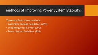
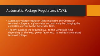
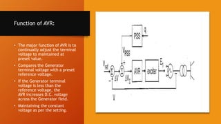
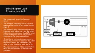
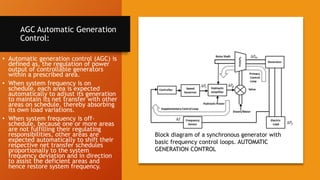
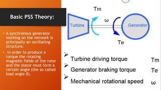
SlideShare a Scribd company logo
IMPROVING POWER
SYSTEM STABILITY
By Ghulam Rasool
Methods of Improving Power System Stability:
There are Basic three methods
• Automatic Voltage Regulators (AVR)
• Load Frequency Control (LFC)
• Power System Stabilizer (PSS)
Automatic Voltage Regulators (AVR):
• Automatic voltage regulator (AVR) maintains the Generator
terminal voltage at a given value automatically by changing the
excitation current to the Generator field.
• The AVR supplies the required D.C. to the Generator field
depending on the load, power factor etc. to maintain a constant
terminal voltage.
Types of AVR:
Single
Channel
AVR
Dual
Channel
AVR
Twin
Channel
AVR
Function of AVR:
• The major function of AVR is to
continually adjust the terminal
voltage to maintained at
preset value.
• Compares the Generator
terminal voltage with a preset
reference voltage.
• If the Generator terminal
voltage is less than the
reference voltage, the
AVR increases D.C. voltage
across the Generator field.
• Maintaining the constant
voltage as per the setting.
Functions of AVR:
• Challenges
The normal feedback control actions of (AVR) & Speed Governor
introducing negative damping which can cause undamped modes of
oscillations (Critically stable).
• Solution
Switching (AVR) from Auto/Manual.
However, removing AVR from service is not realistic solution to the
problem.
Supplementary feedback signal introduced to AVR as PSS.
Load Frequency Control:
• For large scale electric power systems with interconnected areas,
Load Frequency Control (LFC) is important to keep the system
frequency and the inter-area tie power as near to the scheduled
values as possible.
• The input mechanical power to the generators is used to control
the frequency of output electrical power and to maintain the
power exchange between the areas as scheduled.
• The change in frequency is sensed when the rotor angle ∂ is
• changed.
LFC cont.…..
• The change in frequency is sensed when the rotor angle ∂ is changed.
• The error signals are transformed into real power command signal, which is sent to
prime mover to call for an increment in the torque.
• The prime mover then brings change in the generator output by an amount which will
change the values of within the specified tolerance.
• Load frequency control is basic control mechanism in the power system operation.
Whenever there is variation in load demand on a generating unit, there is a
momentarily an occurrence of unbalance between real-power input and output. This
difference is being supplied by the stored energy of the rotating parts of the unit.
• Load Frequency Control (LFC) is being used for several years as part of the Automatic
Generation Control (AGC) scheme in electric power systems. One of the objectives of
AGC is to maintain the system frequency at nominal value (50 Hz).
Block diagram Load
frequency control:
• The frequency is sensed by frequency
sensor.
• The change in frequency and tie line real
power can be measured by change in rotor
angle δ.
• The load frequency controller amplify and
transform error signal, i.e., (Δfi and ΔPtie)
in to real power command signal ΔPci which
is sent to the prime mover via governor
(that control the valve mechanism).
• To call for an increment or decrement in
torque the prime mover balances the output
of governor which will compensate the
value of error signal that is Δfi and ΔPtie.
• The process continues till deviation in form
of Δfi and ΔPtie as well as the specified
tolerance.
Reasons for constant frequency:
• The speed of the alternating current motors depends on the
frequency of the power supply. There are situations where speed
consistency is expected to be of high order.
• If the normal frequency is 50 Hertz and the system frequency falls
below 47.5 Hertz or goes up above 52.5 Hertz then the blades of
the turbine are likely to get damaged so as to prevent the stalling
of the generator.
• Due to the subnormal frequency operation the blast of the
Induced Draft (ID) and Force Draft (FD) fans in the power stations
get reduced and thereby reduce the generation power in the
thermal plants.
AGC Automatic Generation
Control:
• Automatic generation control (AGC) is
defined as, the regulation of power
output of controllable generators
within a prescribed area.
• When system frequency is on
schedule, each area is expected
automatically to adjust its generation
to maintain its net transfer with other
areas on schedule, thereby absorbing
its own load variations.
• When system frequency is off-
schedule, because one or more areas
are not fulfilling their regulating
responsibilities, other areas are
expected automatically to shift their
respective net transfer schedules
proportionally to the system
frequency deviation and in direction
to assist the deficient areas and
hence restore system frequency.
Block diagram of a synchronous generator with
basic frequency control loops. AUTOMATIC
GENERATION CONTROL
Power System Stabilizer:
• The power system stabilizer (PSS) is a device that measures
improvements in system stability when added to a generator’s
automatic voltage regulator (AVR). Therefore, compared to
system reconstruction or enhancement, it offers
overwhelmingly superior cost performance.
• The Power System Stabilizer (PSS) is a supplementary excitation
controller used to damp generator electro-mechanical oscillations
in order to protect the shaft line and stabilise the grid. It
also damps generator rotor angle swings, which are of greater
range in frequencies in power system.
The Main Function of PSS:
• The objectives of PSS is to add damping to rotor oscillations. This
is achieved by modulating the voltage regulator set point to
produce torque variations in phase with speed.
• The PSS will produce variations in electrical torque in phase with
speed and acts to damped out oscillations.
Basic PSS Theory:
• A synchronous generator
working on the network is
principally an oscillating
structure.
• In order to produce a
torque the rotating
magnetic fields of the rotor
and the stator must form a
certain angle (the so called
load angle δ).
Basic PSS Theory: cont…….
• The electrical torque (Te) increases, as the angle (δ) increases,
just similar to a torsion spring. Because during steady-state
operation the electrical torque (Te) of the generator and the
mechanical driving torque (Tm) from the turbine are in
equilibrium, the load angle δ remains in a given position
• The dynamic of the mechanical power (Tm) , electrical power (Te)
, and rotor angular speed (ω) of the synchronous machine is an
origin for theoretical consideration and justifications of the PSS
processing signal.

More Related Content

What's hot

Switchgear presentation
Switchgear presentationSwitchgear presentation
Switchgear presentation
Ahmed Saada, (PRMG)
 
Functions and performance requirements of excitation systems
Functions and performance requirements of excitation systemsFunctions and performance requirements of excitation systems
Functions and performance requirements of excitation systems
Rajshekar Naregal
 
Braking methods of induction motor
Braking methods of induction motorBraking methods of induction motor
Braking methods of induction motor
raviarmugam
 
Frequency Control of Power Systems
Frequency Control of Power SystemsFrequency Control of Power Systems
Frequency Control of Power Systems
Satya Sahoo
 
Transformers protection, an introduction
Transformers protection, an introductionTransformers protection, an introduction
Transformers protection, an introduction
H. Kheir
 
power system analysis PPT
power system analysis PPTpower system analysis PPT
power system analysis PPT
Ziyaulhaq
 
Series & shunt compensation and FACTs Devices
Series & shunt compensation and FACTs DevicesSeries & shunt compensation and FACTs Devices
Series & shunt compensation and FACTs Devices
khemraj298
 
SWITCHYARD EQUIPMENTS & PROTECTION SYSTEMS
SWITCHYARD EQUIPMENTS & PROTECTION SYSTEMSSWITCHYARD EQUIPMENTS & PROTECTION SYSTEMS
SWITCHYARD EQUIPMENTS & PROTECTION SYSTEMS
Partha Parida
 
Power flow solution
Power flow solutionPower flow solution
Power flow solution
Balaram Das
 
Mechanical design of overhead lines
Mechanical design of overhead linesMechanical design of overhead lines
Mechanical design of overhead lines
Md. Rimon Mia
 
Unit 4 Automatic Generation Control
Unit 4 Automatic Generation ControlUnit 4 Automatic Generation Control
Unit 4 Automatic Generation Control
SANTOSH GADEKAR
 
unit-iii- Sphere Gap.ppt
unit-iii- Sphere Gap.pptunit-iii- Sphere Gap.ppt
unit-iii- Sphere Gap.ppt
VijayHiremath26
 
Protection & switchgear
Protection & switchgear   Protection & switchgear
Protection & switchgear
johny renoald
 
Motor protection
Motor protectionMotor protection
Motor protection
H. Kheir
 
Generator and Transformer Protection (PART 1)
Generator and Transformer Protection (PART 1)Generator and Transformer Protection (PART 1)
Generator and Transformer Protection (PART 1)
Dr. Rohit Babu
 
Per unit system
Per unit systemPer unit system
Per unit system
Muhammad Kamran Shaikh
 
Switchgear - complete guide
Switchgear - complete guideSwitchgear - complete guide
Switchgear - complete guide
Slides Hub
 
Electrical machines lecture notes
Electrical machines lecture notesElectrical machines lecture notes
Electrical machines lecture notes
IYAKAREMYE Jean De Dieu
 
statcom
statcomstatcom
statcom
D Målîk
 
Impulse testing of transformer
Impulse testing of transformerImpulse testing of transformer
Impulse testing of transformer
Preet_patel
 

What's hot (20)

Switchgear presentation
Switchgear presentationSwitchgear presentation
Switchgear presentation
 
Functions and performance requirements of excitation systems
Functions and performance requirements of excitation systemsFunctions and performance requirements of excitation systems
Functions and performance requirements of excitation systems
 
Braking methods of induction motor
Braking methods of induction motorBraking methods of induction motor
Braking methods of induction motor
 
Frequency Control of Power Systems
Frequency Control of Power SystemsFrequency Control of Power Systems
Frequency Control of Power Systems
 
Transformers protection, an introduction
Transformers protection, an introductionTransformers protection, an introduction
Transformers protection, an introduction
 
power system analysis PPT
power system analysis PPTpower system analysis PPT
power system analysis PPT
 
Series & shunt compensation and FACTs Devices
Series & shunt compensation and FACTs DevicesSeries & shunt compensation and FACTs Devices
Series & shunt compensation and FACTs Devices
 
SWITCHYARD EQUIPMENTS & PROTECTION SYSTEMS
SWITCHYARD EQUIPMENTS & PROTECTION SYSTEMSSWITCHYARD EQUIPMENTS & PROTECTION SYSTEMS
SWITCHYARD EQUIPMENTS & PROTECTION SYSTEMS
 
Power flow solution
Power flow solutionPower flow solution
Power flow solution
 
Mechanical design of overhead lines
Mechanical design of overhead linesMechanical design of overhead lines
Mechanical design of overhead lines
 
Unit 4 Automatic Generation Control
Unit 4 Automatic Generation ControlUnit 4 Automatic Generation Control
Unit 4 Automatic Generation Control
 
unit-iii- Sphere Gap.ppt
unit-iii- Sphere Gap.pptunit-iii- Sphere Gap.ppt
unit-iii- Sphere Gap.ppt
 
Protection & switchgear
Protection & switchgear   Protection & switchgear
Protection & switchgear
 
Motor protection
Motor protectionMotor protection
Motor protection
 
Generator and Transformer Protection (PART 1)
Generator and Transformer Protection (PART 1)Generator and Transformer Protection (PART 1)
Generator and Transformer Protection (PART 1)
 
Per unit system
Per unit systemPer unit system
Per unit system
 
Switchgear - complete guide
Switchgear - complete guideSwitchgear - complete guide
Switchgear - complete guide
 
Electrical machines lecture notes
Electrical machines lecture notesElectrical machines lecture notes
Electrical machines lecture notes
 
statcom
statcomstatcom
statcom
 
Impulse testing of transformer
Impulse testing of transformerImpulse testing of transformer
Impulse testing of transformer
 

Similar to Power System Control

LOAD FREQUENCY AND VOLTAGE GENERATION CONTROL
LOAD FREQUENCY AND VOLTAGE GENERATION CONTROLLOAD FREQUENCY AND VOLTAGE GENERATION CONTROL
LOAD FREQUENCY AND VOLTAGE GENERATION CONTROL
Preet_patel
 
Power Converters for AC drives CH-1.pptx
Power Converters for AC drives CH-1.pptxPower Converters for AC drives CH-1.pptx
Power Converters for AC drives CH-1.pptx
SuvenduMondal12
 
Different method of frequency and voltage control
Different method of frequency and voltage controlDifferent method of frequency and voltage control
Different method of frequency and voltage control
8141245710
 
Load Frequency Control of Two Area System
Load Frequency Control of Two Area SystemLoad Frequency Control of Two Area System
Load Frequency Control of Two Area System
Manash Deka
 
11305119, roll. no 5, akshay kumar
11305119, roll. no 5, akshay kumar11305119, roll. no 5, akshay kumar
11305119, roll. no 5, akshay kumar
Akshay Kumar
 
Fundamentals of Induction Motor Drives.pptx
Fundamentals of Induction Motor Drives.pptxFundamentals of Induction Motor Drives.pptx
Fundamentals of Induction Motor Drives.pptx
manasideore6
 
Speed Control Of DC Motor
Speed Control Of DC MotorSpeed Control Of DC Motor
Speed Control Of DC Motor
PRAVEEN KUMAR
 
Frequency control & Voltage control.pptx
Frequency control & Voltage control.pptxFrequency control & Voltage control.pptx
Frequency control & Voltage control.pptx
JoseeMusabyimana
 
Frequency Control & AGC.ppt
Frequency Control & AGC.pptFrequency Control & AGC.ppt
Frequency Control & AGC.ppt
Surajit Banerjee
 
Electric-Traction-Railways.ppt
Electric-Traction-Railways.pptElectric-Traction-Railways.ppt
Electric-Traction-Railways.ppt
ssuserf805c8
 
Automatic voltaer regulator and it's modelling
Automatic voltaer regulator and it's modellingAutomatic voltaer regulator and it's modelling
Automatic voltaer regulator and it's modelling
rajani51
 
Introduction_to_Mechatronics_Chapter3.pdf
Introduction_to_Mechatronics_Chapter3.pdfIntroduction_to_Mechatronics_Chapter3.pdf
Introduction_to_Mechatronics_Chapter3.pdf
Bereket Walle
 
PQH 3rd chapter.pptx
PQH 3rd chapter.pptxPQH 3rd chapter.pptx
PQH 3rd chapter.pptx
shitaljadhav591046
 
Automatic Generation Control
Automatic Generation ControlAutomatic Generation Control
Automatic Generation Control
Birju Besra
 
Active front end drive
Active front end driveActive front end drive
Active front end drive
mikkumar5
 
EDS Unit 6.pptx
EDS Unit 6.pptxEDS Unit 6.pptx
EDS Unit 6.pptx
Dr. Rohit Babu
 
load frequency control of two area
load frequency control of two areaload frequency control of two area
load frequency control of two area
Sumit Patel
 
Excitation Systems.pptx
 Excitation Systems.pptx Excitation Systems.pptx
Excitation Systems.pptx
MahimaSrivastava26
 
AVR.pptx
AVR.pptxAVR.pptx
AVR.pptx
AhmedHammam45
 
Duly fed induction generator
Duly fed induction generatorDuly fed induction generator
Duly fed induction generator
SonuKumarBairwa
 

Similar to Power System Control (20)

LOAD FREQUENCY AND VOLTAGE GENERATION CONTROL
LOAD FREQUENCY AND VOLTAGE GENERATION CONTROLLOAD FREQUENCY AND VOLTAGE GENERATION CONTROL
LOAD FREQUENCY AND VOLTAGE GENERATION CONTROL
 
Power Converters for AC drives CH-1.pptx
Power Converters for AC drives CH-1.pptxPower Converters for AC drives CH-1.pptx
Power Converters for AC drives CH-1.pptx
 
Different method of frequency and voltage control
Different method of frequency and voltage controlDifferent method of frequency and voltage control
Different method of frequency and voltage control
 
Load Frequency Control of Two Area System
Load Frequency Control of Two Area SystemLoad Frequency Control of Two Area System
Load Frequency Control of Two Area System
 
11305119, roll. no 5, akshay kumar
11305119, roll. no 5, akshay kumar11305119, roll. no 5, akshay kumar
11305119, roll. no 5, akshay kumar
 
Fundamentals of Induction Motor Drives.pptx
Fundamentals of Induction Motor Drives.pptxFundamentals of Induction Motor Drives.pptx
Fundamentals of Induction Motor Drives.pptx
 
Speed Control Of DC Motor
Speed Control Of DC MotorSpeed Control Of DC Motor
Speed Control Of DC Motor
 
Frequency control & Voltage control.pptx
Frequency control & Voltage control.pptxFrequency control & Voltage control.pptx
Frequency control & Voltage control.pptx
 
Frequency Control & AGC.ppt
Frequency Control & AGC.pptFrequency Control & AGC.ppt
Frequency Control & AGC.ppt
 
Electric-Traction-Railways.ppt
Electric-Traction-Railways.pptElectric-Traction-Railways.ppt
Electric-Traction-Railways.ppt
 
Automatic voltaer regulator and it's modelling
Automatic voltaer regulator and it's modellingAutomatic voltaer regulator and it's modelling
Automatic voltaer regulator and it's modelling
 
Introduction_to_Mechatronics_Chapter3.pdf
Introduction_to_Mechatronics_Chapter3.pdfIntroduction_to_Mechatronics_Chapter3.pdf
Introduction_to_Mechatronics_Chapter3.pdf
 
PQH 3rd chapter.pptx
PQH 3rd chapter.pptxPQH 3rd chapter.pptx
PQH 3rd chapter.pptx
 
Automatic Generation Control
Automatic Generation ControlAutomatic Generation Control
Automatic Generation Control
 
Active front end drive
Active front end driveActive front end drive
Active front end drive
 
EDS Unit 6.pptx
EDS Unit 6.pptxEDS Unit 6.pptx
EDS Unit 6.pptx
 
load frequency control of two area
load frequency control of two areaload frequency control of two area
load frequency control of two area
 
Excitation Systems.pptx
 Excitation Systems.pptx Excitation Systems.pptx
Excitation Systems.pptx
 
AVR.pptx
AVR.pptxAVR.pptx
AVR.pptx
 
Duly fed induction generator
Duly fed induction generatorDuly fed induction generator
Duly fed induction generator
 

Recently uploaded

Data Driven Maintenance | UReason Webinar
Data Driven Maintenance | UReason WebinarData Driven Maintenance | UReason Webinar
Data Driven Maintenance | UReason Webinar
UReason
 
一比一原版(uoft毕业证书)加拿大多伦多大学毕业证如何办理
一比一原版(uoft毕业证书)加拿大多伦多大学毕业证如何办理一比一原版(uoft毕业证书)加拿大多伦多大学毕业证如何办理
一比一原版(uoft毕业证书)加拿大多伦多大学毕业证如何办理
sydezfe
 
DEEP LEARNING FOR SMART GRID INTRUSION DETECTION: A HYBRID CNN-LSTM-BASED MODEL
DEEP LEARNING FOR SMART GRID INTRUSION DETECTION: A HYBRID CNN-LSTM-BASED MODELDEEP LEARNING FOR SMART GRID INTRUSION DETECTION: A HYBRID CNN-LSTM-BASED MODEL
DEEP LEARNING FOR SMART GRID INTRUSION DETECTION: A HYBRID CNN-LSTM-BASED MODEL
ijaia
 
SCALING OF MOS CIRCUITS m .pptx
SCALING OF MOS CIRCUITS m                 .pptxSCALING OF MOS CIRCUITS m                 .pptx
SCALING OF MOS CIRCUITS m .pptx
harshapolam10
 
原版制作(Humboldt毕业证书)柏林大学毕业证学位证一模一样
原版制作(Humboldt毕业证书)柏林大学毕业证学位证一模一样原版制作(Humboldt毕业证书)柏林大学毕业证学位证一模一样
原版制作(Humboldt毕业证书)柏林大学毕业证学位证一模一样
ydzowc
 
SENTIMENT ANALYSIS ON PPT AND Project template_.pptx
SENTIMENT ANALYSIS ON PPT AND Project template_.pptxSENTIMENT ANALYSIS ON PPT AND Project template_.pptx
SENTIMENT ANALYSIS ON PPT AND Project template_.pptx
b0754201
 
Prediction of Electrical Energy Efficiency Using Information on Consumer's Ac...
Prediction of Electrical Energy Efficiency Using Information on Consumer's Ac...Prediction of Electrical Energy Efficiency Using Information on Consumer's Ac...
Prediction of Electrical Energy Efficiency Using Information on Consumer's Ac...
PriyankaKilaniya
 
Mechatronics material . Mechanical engineering
Mechatronics material . Mechanical engineeringMechatronics material . Mechanical engineering
Mechatronics material . Mechanical engineering
sachin chaurasia
 
ITSM Integration with MuleSoft.pptx
ITSM  Integration with MuleSoft.pptxITSM  Integration with MuleSoft.pptx
ITSM Integration with MuleSoft.pptx
VANDANAMOHANGOUDA
 
一比一原版(uofo毕业证书)美国俄勒冈大学毕业证如何办理
一比一原版(uofo毕业证书)美国俄勒冈大学毕业证如何办理一比一原版(uofo毕业证书)美国俄勒冈大学毕业证如何办理
一比一原版(uofo毕业证书)美国俄勒冈大学毕业证如何办理
upoux
 
Open Channel Flow: fluid flow with a free surface
Open Channel Flow: fluid flow with a free surfaceOpen Channel Flow: fluid flow with a free surface
Open Channel Flow: fluid flow with a free surface
Indrajeet sahu
 
P5 Working Drawings.pdf floor plan, civil
P5 Working Drawings.pdf floor plan, civilP5 Working Drawings.pdf floor plan, civil
P5 Working Drawings.pdf floor plan, civil
AnasAhmadNoor
 
LLM Fine Tuning with QLoRA Cassandra Lunch 4, presented by Anant
LLM Fine Tuning with QLoRA Cassandra Lunch 4, presented by AnantLLM Fine Tuning with QLoRA Cassandra Lunch 4, presented by Anant
LLM Fine Tuning with QLoRA Cassandra Lunch 4, presented by Anant
Anant Corporation
 
Digital Twins Computer Networking Paper Presentation.pptx
Digital Twins Computer Networking Paper Presentation.pptxDigital Twins Computer Networking Paper Presentation.pptx
Digital Twins Computer Networking Paper Presentation.pptx
aryanpankaj78
 
Transformers design and coooling methods
Transformers design and coooling methodsTransformers design and coooling methods
Transformers design and coooling methods
Roger Rozario
 
一比一原版(爱大毕业证书)爱荷华大学毕业证如何办理
一比一原版(爱大毕业证书)爱荷华大学毕业证如何办理一比一原版(爱大毕业证书)爱荷华大学毕业证如何办理
一比一原版(爱大毕业证书)爱荷华大学毕业证如何办理
nedcocy
 
Supermarket Management System Project Report.pdf
Supermarket Management System Project Report.pdfSupermarket Management System Project Report.pdf
Supermarket Management System Project Report.pdf
Kamal Acharya
 
一比一原版(USF毕业证)旧金山大学毕业证如何办理
一比一原版(USF毕业证)旧金山大学毕业证如何办理一比一原版(USF毕业证)旧金山大学毕业证如何办理
一比一原版(USF毕业证)旧金山大学毕业证如何办理
uqyfuc
 
1FIDIC-CONSTRUCTION-CONTRACT-2ND-ED-2017-RED-BOOK.pdf
1FIDIC-CONSTRUCTION-CONTRACT-2ND-ED-2017-RED-BOOK.pdf1FIDIC-CONSTRUCTION-CONTRACT-2ND-ED-2017-RED-BOOK.pdf
1FIDIC-CONSTRUCTION-CONTRACT-2ND-ED-2017-RED-BOOK.pdf
MadhavJungKarki
 
AI-Based Home Security System : Home security
AI-Based Home Security System : Home securityAI-Based Home Security System : Home security
AI-Based Home Security System : Home security
AIRCC Publishing Corporation
 

Recently uploaded (20)

Data Driven Maintenance | UReason Webinar
Data Driven Maintenance | UReason WebinarData Driven Maintenance | UReason Webinar
Data Driven Maintenance | UReason Webinar
 
一比一原版(uoft毕业证书)加拿大多伦多大学毕业证如何办理
一比一原版(uoft毕业证书)加拿大多伦多大学毕业证如何办理一比一原版(uoft毕业证书)加拿大多伦多大学毕业证如何办理
一比一原版(uoft毕业证书)加拿大多伦多大学毕业证如何办理
 
DEEP LEARNING FOR SMART GRID INTRUSION DETECTION: A HYBRID CNN-LSTM-BASED MODEL
DEEP LEARNING FOR SMART GRID INTRUSION DETECTION: A HYBRID CNN-LSTM-BASED MODELDEEP LEARNING FOR SMART GRID INTRUSION DETECTION: A HYBRID CNN-LSTM-BASED MODEL
DEEP LEARNING FOR SMART GRID INTRUSION DETECTION: A HYBRID CNN-LSTM-BASED MODEL
 
SCALING OF MOS CIRCUITS m .pptx
SCALING OF MOS CIRCUITS m                 .pptxSCALING OF MOS CIRCUITS m                 .pptx
SCALING OF MOS CIRCUITS m .pptx
 
原版制作(Humboldt毕业证书)柏林大学毕业证学位证一模一样
原版制作(Humboldt毕业证书)柏林大学毕业证学位证一模一样原版制作(Humboldt毕业证书)柏林大学毕业证学位证一模一样
原版制作(Humboldt毕业证书)柏林大学毕业证学位证一模一样
 
SENTIMENT ANALYSIS ON PPT AND Project template_.pptx
SENTIMENT ANALYSIS ON PPT AND Project template_.pptxSENTIMENT ANALYSIS ON PPT AND Project template_.pptx
SENTIMENT ANALYSIS ON PPT AND Project template_.pptx
 
Prediction of Electrical Energy Efficiency Using Information on Consumer's Ac...
Prediction of Electrical Energy Efficiency Using Information on Consumer's Ac...Prediction of Electrical Energy Efficiency Using Information on Consumer's Ac...
Prediction of Electrical Energy Efficiency Using Information on Consumer's Ac...
 
Mechatronics material . Mechanical engineering
Mechatronics material . Mechanical engineeringMechatronics material . Mechanical engineering
Mechatronics material . Mechanical engineering
 
ITSM Integration with MuleSoft.pptx
ITSM  Integration with MuleSoft.pptxITSM  Integration with MuleSoft.pptx
ITSM Integration with MuleSoft.pptx
 
一比一原版(uofo毕业证书)美国俄勒冈大学毕业证如何办理
一比一原版(uofo毕业证书)美国俄勒冈大学毕业证如何办理一比一原版(uofo毕业证书)美国俄勒冈大学毕业证如何办理
一比一原版(uofo毕业证书)美国俄勒冈大学毕业证如何办理
 
Open Channel Flow: fluid flow with a free surface
Open Channel Flow: fluid flow with a free surfaceOpen Channel Flow: fluid flow with a free surface
Open Channel Flow: fluid flow with a free surface
 
P5 Working Drawings.pdf floor plan, civil
P5 Working Drawings.pdf floor plan, civilP5 Working Drawings.pdf floor plan, civil
P5 Working Drawings.pdf floor plan, civil
 
LLM Fine Tuning with QLoRA Cassandra Lunch 4, presented by Anant
LLM Fine Tuning with QLoRA Cassandra Lunch 4, presented by AnantLLM Fine Tuning with QLoRA Cassandra Lunch 4, presented by Anant
LLM Fine Tuning with QLoRA Cassandra Lunch 4, presented by Anant
 
Digital Twins Computer Networking Paper Presentation.pptx
Digital Twins Computer Networking Paper Presentation.pptxDigital Twins Computer Networking Paper Presentation.pptx
Digital Twins Computer Networking Paper Presentation.pptx
 
Transformers design and coooling methods
Transformers design and coooling methodsTransformers design and coooling methods
Transformers design and coooling methods
 
一比一原版(爱大毕业证书)爱荷华大学毕业证如何办理
一比一原版(爱大毕业证书)爱荷华大学毕业证如何办理一比一原版(爱大毕业证书)爱荷华大学毕业证如何办理
一比一原版(爱大毕业证书)爱荷华大学毕业证如何办理
 
Supermarket Management System Project Report.pdf
Supermarket Management System Project Report.pdfSupermarket Management System Project Report.pdf
Supermarket Management System Project Report.pdf
 
一比一原版(USF毕业证)旧金山大学毕业证如何办理
一比一原版(USF毕业证)旧金山大学毕业证如何办理一比一原版(USF毕业证)旧金山大学毕业证如何办理
一比一原版(USF毕业证)旧金山大学毕业证如何办理
 
1FIDIC-CONSTRUCTION-CONTRACT-2ND-ED-2017-RED-BOOK.pdf
1FIDIC-CONSTRUCTION-CONTRACT-2ND-ED-2017-RED-BOOK.pdf1FIDIC-CONSTRUCTION-CONTRACT-2ND-ED-2017-RED-BOOK.pdf
1FIDIC-CONSTRUCTION-CONTRACT-2ND-ED-2017-RED-BOOK.pdf
 
AI-Based Home Security System : Home security
AI-Based Home Security System : Home securityAI-Based Home Security System : Home security
AI-Based Home Security System : Home security
 

Power System Control

  • 2. Methods of Improving Power System Stability: There are Basic three methods • Automatic Voltage Regulators (AVR) • Load Frequency Control (LFC) • Power System Stabilizer (PSS)
  • 3. Automatic Voltage Regulators (AVR): • Automatic voltage regulator (AVR) maintains the Generator terminal voltage at a given value automatically by changing the excitation current to the Generator field. • The AVR supplies the required D.C. to the Generator field depending on the load, power factor etc. to maintain a constant terminal voltage.
  • 5. Function of AVR: • The major function of AVR is to continually adjust the terminal voltage to maintained at preset value. • Compares the Generator terminal voltage with a preset reference voltage. • If the Generator terminal voltage is less than the reference voltage, the AVR increases D.C. voltage across the Generator field. • Maintaining the constant voltage as per the setting.
  • 6. Functions of AVR: • Challenges The normal feedback control actions of (AVR) & Speed Governor introducing negative damping which can cause undamped modes of oscillations (Critically stable). • Solution Switching (AVR) from Auto/Manual. However, removing AVR from service is not realistic solution to the problem. Supplementary feedback signal introduced to AVR as PSS.
  • 7. Load Frequency Control: • For large scale electric power systems with interconnected areas, Load Frequency Control (LFC) is important to keep the system frequency and the inter-area tie power as near to the scheduled values as possible. • The input mechanical power to the generators is used to control the frequency of output electrical power and to maintain the power exchange between the areas as scheduled. • The change in frequency is sensed when the rotor angle ∂ is • changed.
  • 8. LFC cont.….. • The change in frequency is sensed when the rotor angle ∂ is changed. • The error signals are transformed into real power command signal, which is sent to prime mover to call for an increment in the torque. • The prime mover then brings change in the generator output by an amount which will change the values of within the specified tolerance. • Load frequency control is basic control mechanism in the power system operation. Whenever there is variation in load demand on a generating unit, there is a momentarily an occurrence of unbalance between real-power input and output. This difference is being supplied by the stored energy of the rotating parts of the unit. • Load Frequency Control (LFC) is being used for several years as part of the Automatic Generation Control (AGC) scheme in electric power systems. One of the objectives of AGC is to maintain the system frequency at nominal value (50 Hz).
  • 9. Block diagram Load frequency control: • The frequency is sensed by frequency sensor. • The change in frequency and tie line real power can be measured by change in rotor angle δ. • The load frequency controller amplify and transform error signal, i.e., (Δfi and ΔPtie) in to real power command signal ΔPci which is sent to the prime mover via governor (that control the valve mechanism). • To call for an increment or decrement in torque the prime mover balances the output of governor which will compensate the value of error signal that is Δfi and ΔPtie. • The process continues till deviation in form of Δfi and ΔPtie as well as the specified tolerance.
  • 10. Reasons for constant frequency: • The speed of the alternating current motors depends on the frequency of the power supply. There are situations where speed consistency is expected to be of high order. • If the normal frequency is 50 Hertz and the system frequency falls below 47.5 Hertz or goes up above 52.5 Hertz then the blades of the turbine are likely to get damaged so as to prevent the stalling of the generator. • Due to the subnormal frequency operation the blast of the Induced Draft (ID) and Force Draft (FD) fans in the power stations get reduced and thereby reduce the generation power in the thermal plants.
  • 11. AGC Automatic Generation Control: • Automatic generation control (AGC) is defined as, the regulation of power output of controllable generators within a prescribed area. • When system frequency is on schedule, each area is expected automatically to adjust its generation to maintain its net transfer with other areas on schedule, thereby absorbing its own load variations. • When system frequency is off- schedule, because one or more areas are not fulfilling their regulating responsibilities, other areas are expected automatically to shift their respective net transfer schedules proportionally to the system frequency deviation and in direction to assist the deficient areas and hence restore system frequency. Block diagram of a synchronous generator with basic frequency control loops. AUTOMATIC GENERATION CONTROL
  • 12. Power System Stabilizer: • The power system stabilizer (PSS) is a device that measures improvements in system stability when added to a generator’s automatic voltage regulator (AVR). Therefore, compared to system reconstruction or enhancement, it offers overwhelmingly superior cost performance. • The Power System Stabilizer (PSS) is a supplementary excitation controller used to damp generator electro-mechanical oscillations in order to protect the shaft line and stabilise the grid. It also damps generator rotor angle swings, which are of greater range in frequencies in power system.
  • 13. The Main Function of PSS: • The objectives of PSS is to add damping to rotor oscillations. This is achieved by modulating the voltage regulator set point to produce torque variations in phase with speed. • The PSS will produce variations in electrical torque in phase with speed and acts to damped out oscillations.
  • 14. Basic PSS Theory: • A synchronous generator working on the network is principally an oscillating structure. • In order to produce a torque the rotating magnetic fields of the rotor and the stator must form a certain angle (the so called load angle δ).
  • 15. Basic PSS Theory: cont……. • The electrical torque (Te) increases, as the angle (δ) increases, just similar to a torsion spring. Because during steady-state operation the electrical torque (Te) of the generator and the mechanical driving torque (Tm) from the turbine are in equilibrium, the load angle δ remains in a given position • The dynamic of the mechanical power (Tm) , electrical power (Te) , and rotor angular speed (ω) of the synchronous machine is an origin for theoretical consideration and justifications of the PSS processing signal.