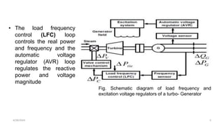
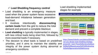
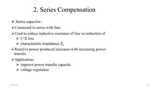
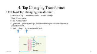
Voltage control: Reactive power, shunt
capacitors; Tap changing transformers
Frequency control: Primary control,
Secondary control, Load shedding
4/28/2024 1
4/28/2024 2
• Frequency control is crucial for maintaining the stability, reliability, and integrity
of power systems. It ensures that the supply and demand of electrical power are
constantly balanced, preventing frequency deviations that could lead to
equipment damage, power outages, or even cascading failures across the grid
• In a power system, the frequency is determined by the balance between power
generation and load demand.
• The frequency is typically set to a specific value, such as 50 Hz or 60 Hz,
depending on the region. Any mismatch between generation and load will
cause the frequency to deviate from this nominal value.
• To ensure proper frequency control, power systems employ various control
mechanisms, including primary control (automatic generation control or AGC),
secondary control (automatic voltage control or AVC) and load frequency
control (LFC) . These mechanisms work together to maintain the system
frequency within an acceptable range
 Frequency control: Primary control, Secondary
control, Load shedding
4/28/2024 3
• The purpose of AGC is maintain power balance in the system
• Primary control, or AGC, operates on a fast timescale (seconds to minutes)
and is responsible for immediate adjustments to the power output of
generators.
• It continuously monitors the frequency and compares it to the reference
value. If the frequency deviates, control signals are sent to the generators to
adjust their power output accordingly.
• Generators increase or decrease their output to bring the system back into
balance.
• To maintain power balance, generators need to produce more or less to
keep up with the load
• When Gen < Load (Gen > Load), generator speed and frequency will drop
(rise).=> We use this generator speed and frequency as control signals!
 Primary Control (AGC) frequency control
4/28/2024 4
 Secondary Control (AVR) frequency control
• Under excitation in a generator occurs when the field current supplied
to the rotor winding of the generator is insufficient to produce the
required magnetic field strength. This condition leads to a decrease in
the generator's terminal voltage compared to the normal or rated
voltage.
• A generator is said to be over-excited when its field current is
increased beyond the level required to produce the rated voltage at the
generator terminals. This over-excitation increases the voltage output
of the generator
Secondary Control (Automatic Voltage Control):
Secondary control, also known as automatic voltage control (AVC), is a
slower control mechanism that operates on a timescale of minutes to
hours. It aims to restore the system frequency and voltage to their
nominal values after primary control has made immediate adjustments.
Secondary control involves more comprehensive coordination between
4/28/2024 5
Fig. Schematic diagram of load frequency and
excitation voltage regulators of a turbo- Generator
• The load frequency
control (LFC) loop
controls the real power
and frequency and the
automatic voltage
regulator (AVR) loop
regulates the reactive
power and voltage
magnitude
4/28/2024 6
• Load shedding is an emergency measure
used when the power system faces excessive
load-demand imbalance between generation
and load.
 Load Shedding frequency control
• Load shedding is typically implemented in stages,
with less critical loads being shed first, followed by
more essential loads if necessary.
Load shedding implemented
stages for example
https://www.linkedin.com/advice/0/how-
can-you-design-load-shedding-strategy-
prevent#:~:text=These%20criteria%20can
%20be%20based,value%2C%20indicating
%20a%20generation%20deficiency.
• It involves intentionally disconnecting
certain loads from the grid to reduce the total
demand and prevent a complete blackout.
• The decision to shed loads is based on predefined
priorities, and it aims to maintain the stability and
integrity of the power system during abnormal or
emergency conditions
4/28/2024 7
 Voltage control: Reactive power, shunt capacitors;
Tap changing transformers
• Voltage control is an important aspect of electrical power systems to
ensure the stability and reliability of the grid.
• Reactive power compensation is one method used for voltage control,
and shunt capacitors play a significant role in this process.
• Tap changing transformers are also employed to regulate voltage levels
in power systems.
• Change in real power affect mainly the system frequency, while
reactive power is less sensitive to changes in frequency and is mainly
dependent on changes in voltage magnitude
Methods of
Voltage Control
1. Shunt compensation
2. Series capacitor
3. Synchronous condenser
4. Tap changing transformer
5. Auto transformer tap
changing
4/28/2024 8
1. Shunt Compensation
 Shunt Reactor :
• Used to compensate effect line capacitance by
limiting voltage rise on an open circuit or light load
• They are connected either:
 directly to the lines at the ends
 Tertiary windings easily switched as VAR
vary.
 In long lines to overcome ferranti effect.
 Connected to bus bar without C.B for switching.
 Shunt Capacitor :
• Supply leading reactive power and boost the voltage
as loading of current reduces.
• Switching substation inductive load absorb
inductive current of lower P.F.
• They are connected either:
• H.V
. bus
• Tertiary winding of transformers
4/28/2024 9
2. Series Compensation
 Series capacitor :
Connected in series with line.
Used to reduce inductive reactance of line so reduction of
 I 2X loss
 characteristic impedance ZC
Reactive power produced increases with increasing power
transfer.
Application :
 improve power transfer capacity.
 voltage regulation
4/28/2024 10
3. Synchronous Condenser
A synchronous machine running without a prime mover or a
mechanical load
Depending on field excitation, it can either absorb or generate VARs
With a voltage regulator, it can automatically adjust VAR to maintain
constant voltage
Started as an induction motor and then synchronized
Normally connected to tertiary windings of transformers
Unlike a SVC, a synchronous condenser has an internal voltage
Speed of response not as fast as that of an SVC
4/28/2024 11
4. Tap Changing Transformer
• Off load Tap changing transformer :
• Position of tap number of turns output voltage.
• Stud 1 : min value
• Stud 5 : max value
• Light load primary voltage = alternator voltages and movable arm is
placed at stud 1.
• Load drop so movement of stud.
4/28/2024 12
• On load Tap changing transformer :
• widely used so no interruption of supply voltage
• Secondary divided into two parallel path so current divided.
• Tap changing operation is performed one after other.
• Disadvantages :
• Voltage surge due to high voltage drop.
• Num of tapings = 2 * voltage steps.
4/28/2024 13
5. Auto Transformer
• Mid tapped auto transformer is used.
• Connected with one side of line, divided into two parts.
• Odd switches and even switches
• Normal operation no drop
• Tap changing high drop large circulating current flow
control by reactor.
4/28/2024 14
Reactive Power and Voltage Control:
Reactive power is the component of power that oscillates between the
generation and consumption points in an alternating current (AC) system. It is
responsible for establishing and maintaining the desired voltage levels within
acceptable limits.
Reactive power compensation is the process of injecting or absorbing reactive
power into or from the power system to regulate voltage. Shunt capacitors are
commonly used for reactive power compensation. These capacitors absorb
reactive power, thereby reducing the system's reactive power flow and
increasing the voltage levels. By compensating for the reactive power demand,
shunt capacitors help maintain voltage stability and improve the power factor of
the system.
4/28/2024 15
Shunt Capacitors:
Shunt capacitors are connected in parallel with the load or on the
distribution feeder to supply reactive power to the system. They consist of
banks of capacitors that are switched on or off based on the system's
reactive power requirements.
When the load on a power system is predominantly inductive (such as
motors and transformers), it consumes reactive power. By installing shunt
capacitors, the reactive power demand is met, leading to a reduction in
the reactive power flow and voltage rise. Shunt capacitors are particularly
useful in distribution systems to compensate for the reactive power
demand of industrial and commercial loads.
4/28/2024 16
4/28/2024 17
Tap Changing Transformers:
Tap changing transformers (also known as on-load tap changers or
OLTCs) are transformers equipped with multiple taps on their windings.
These taps allow for adjustment of the transformer's turns ratio, thereby
regulating the voltage levels.
Tap changing transformers are employed in power systems where
voltage regulation is necessary due to load variations or long
transmission and distribution lines. By changing the tap position, the
transformer's voltage ratio can be adjusted, compensating for voltage
fluctuations and maintaining acceptable voltage levels at the load end.
Automatic tap changers (ATCs) are commonly used in tap changing
transformers to monitor the system voltage and adjust the taps
automatically based on pre-defined control strategies. This ensures
continuous voltage control without interrupting the power supply.

Frequency control & Voltage control.pptx

  • 1.
    Voltage control: Reactivepower, shunt capacitors; Tap changing transformers Frequency control: Primary control, Secondary control, Load shedding 4/28/2024 1
  • 2.
    4/28/2024 2 • Frequencycontrol is crucial for maintaining the stability, reliability, and integrity of power systems. It ensures that the supply and demand of electrical power are constantly balanced, preventing frequency deviations that could lead to equipment damage, power outages, or even cascading failures across the grid • In a power system, the frequency is determined by the balance between power generation and load demand. • The frequency is typically set to a specific value, such as 50 Hz or 60 Hz, depending on the region. Any mismatch between generation and load will cause the frequency to deviate from this nominal value. • To ensure proper frequency control, power systems employ various control mechanisms, including primary control (automatic generation control or AGC), secondary control (automatic voltage control or AVC) and load frequency control (LFC) . These mechanisms work together to maintain the system frequency within an acceptable range  Frequency control: Primary control, Secondary control, Load shedding
  • 3.
    4/28/2024 3 • Thepurpose of AGC is maintain power balance in the system • Primary control, or AGC, operates on a fast timescale (seconds to minutes) and is responsible for immediate adjustments to the power output of generators. • It continuously monitors the frequency and compares it to the reference value. If the frequency deviates, control signals are sent to the generators to adjust their power output accordingly. • Generators increase or decrease their output to bring the system back into balance. • To maintain power balance, generators need to produce more or less to keep up with the load • When Gen < Load (Gen > Load), generator speed and frequency will drop (rise).=> We use this generator speed and frequency as control signals!  Primary Control (AGC) frequency control
  • 4.
    4/28/2024 4  SecondaryControl (AVR) frequency control • Under excitation in a generator occurs when the field current supplied to the rotor winding of the generator is insufficient to produce the required magnetic field strength. This condition leads to a decrease in the generator's terminal voltage compared to the normal or rated voltage. • A generator is said to be over-excited when its field current is increased beyond the level required to produce the rated voltage at the generator terminals. This over-excitation increases the voltage output of the generator Secondary Control (Automatic Voltage Control): Secondary control, also known as automatic voltage control (AVC), is a slower control mechanism that operates on a timescale of minutes to hours. It aims to restore the system frequency and voltage to their nominal values after primary control has made immediate adjustments. Secondary control involves more comprehensive coordination between
  • 5.
    4/28/2024 5 Fig. Schematicdiagram of load frequency and excitation voltage regulators of a turbo- Generator • The load frequency control (LFC) loop controls the real power and frequency and the automatic voltage regulator (AVR) loop regulates the reactive power and voltage magnitude
  • 6.
    4/28/2024 6 • Loadshedding is an emergency measure used when the power system faces excessive load-demand imbalance between generation and load.  Load Shedding frequency control • Load shedding is typically implemented in stages, with less critical loads being shed first, followed by more essential loads if necessary. Load shedding implemented stages for example https://www.linkedin.com/advice/0/how- can-you-design-load-shedding-strategy- prevent#:~:text=These%20criteria%20can %20be%20based,value%2C%20indicating %20a%20generation%20deficiency. • It involves intentionally disconnecting certain loads from the grid to reduce the total demand and prevent a complete blackout. • The decision to shed loads is based on predefined priorities, and it aims to maintain the stability and integrity of the power system during abnormal or emergency conditions
  • 7.
    4/28/2024 7  Voltagecontrol: Reactive power, shunt capacitors; Tap changing transformers • Voltage control is an important aspect of electrical power systems to ensure the stability and reliability of the grid. • Reactive power compensation is one method used for voltage control, and shunt capacitors play a significant role in this process. • Tap changing transformers are also employed to regulate voltage levels in power systems. • Change in real power affect mainly the system frequency, while reactive power is less sensitive to changes in frequency and is mainly dependent on changes in voltage magnitude Methods of Voltage Control 1. Shunt compensation 2. Series capacitor 3. Synchronous condenser 4. Tap changing transformer 5. Auto transformer tap changing
  • 8.
    4/28/2024 8 1. ShuntCompensation  Shunt Reactor : • Used to compensate effect line capacitance by limiting voltage rise on an open circuit or light load • They are connected either:  directly to the lines at the ends  Tertiary windings easily switched as VAR vary.  In long lines to overcome ferranti effect.  Connected to bus bar without C.B for switching.
  • 9.
     Shunt Capacitor: • Supply leading reactive power and boost the voltage as loading of current reduces. • Switching substation inductive load absorb inductive current of lower P.F. • They are connected either: • H.V . bus • Tertiary winding of transformers 4/28/2024 9
  • 10.
    2. Series Compensation Series capacitor : Connected in series with line. Used to reduce inductive reactance of line so reduction of  I 2X loss  characteristic impedance ZC Reactive power produced increases with increasing power transfer. Application :  improve power transfer capacity.  voltage regulation 4/28/2024 10
  • 11.
    3. Synchronous Condenser Asynchronous machine running without a prime mover or a mechanical load Depending on field excitation, it can either absorb or generate VARs With a voltage regulator, it can automatically adjust VAR to maintain constant voltage Started as an induction motor and then synchronized Normally connected to tertiary windings of transformers Unlike a SVC, a synchronous condenser has an internal voltage Speed of response not as fast as that of an SVC 4/28/2024 11
  • 12.
    4. Tap ChangingTransformer • Off load Tap changing transformer : • Position of tap number of turns output voltage. • Stud 1 : min value • Stud 5 : max value • Light load primary voltage = alternator voltages and movable arm is placed at stud 1. • Load drop so movement of stud. 4/28/2024 12
  • 13.
    • On loadTap changing transformer : • widely used so no interruption of supply voltage • Secondary divided into two parallel path so current divided. • Tap changing operation is performed one after other. • Disadvantages : • Voltage surge due to high voltage drop. • Num of tapings = 2 * voltage steps. 4/28/2024 13
  • 14.
    5. Auto Transformer •Mid tapped auto transformer is used. • Connected with one side of line, divided into two parts. • Odd switches and even switches • Normal operation no drop • Tap changing high drop large circulating current flow control by reactor. 4/28/2024 14
  • 15.
    Reactive Power andVoltage Control: Reactive power is the component of power that oscillates between the generation and consumption points in an alternating current (AC) system. It is responsible for establishing and maintaining the desired voltage levels within acceptable limits. Reactive power compensation is the process of injecting or absorbing reactive power into or from the power system to regulate voltage. Shunt capacitors are commonly used for reactive power compensation. These capacitors absorb reactive power, thereby reducing the system's reactive power flow and increasing the voltage levels. By compensating for the reactive power demand, shunt capacitors help maintain voltage stability and improve the power factor of the system. 4/28/2024 15
  • 16.
    Shunt Capacitors: Shunt capacitorsare connected in parallel with the load or on the distribution feeder to supply reactive power to the system. They consist of banks of capacitors that are switched on or off based on the system's reactive power requirements. When the load on a power system is predominantly inductive (such as motors and transformers), it consumes reactive power. By installing shunt capacitors, the reactive power demand is met, leading to a reduction in the reactive power flow and voltage rise. Shunt capacitors are particularly useful in distribution systems to compensate for the reactive power demand of industrial and commercial loads. 4/28/2024 16
  • 17.
    4/28/2024 17 Tap ChangingTransformers: Tap changing transformers (also known as on-load tap changers or OLTCs) are transformers equipped with multiple taps on their windings. These taps allow for adjustment of the transformer's turns ratio, thereby regulating the voltage levels. Tap changing transformers are employed in power systems where voltage regulation is necessary due to load variations or long transmission and distribution lines. By changing the tap position, the transformer's voltage ratio can be adjusted, compensating for voltage fluctuations and maintaining acceptable voltage levels at the load end. Automatic tap changers (ATCs) are commonly used in tap changing transformers to monitor the system voltage and adjust the taps automatically based on pre-defined control strategies. This ensures continuous voltage control without interrupting the power supply.

Editor's Notes

  • #2 https://slideplayer.com/slide/8109404/
  • #5 Leading power factor: If field excitation is such that Eb < V the generator is said to be under excited and it has a leading power factor. So that it absorved reactive power. Lagging power factor: If field excitation is such that Eb > V the generator is said to be over-excited and it draw lagging current.
  • #7 https://www.linkedin.com/advice/0/how-can-you-design-load-shedding-strategy-prevent#:~:text=These%20criteria%20can%20be%20based,value%2C%20indicating%20a%20generation%20deficiency.