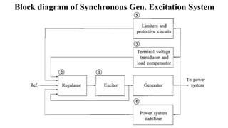
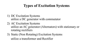
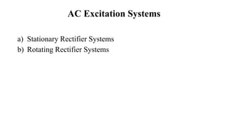
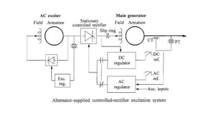
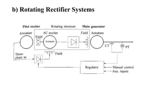
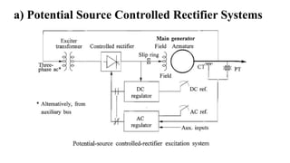
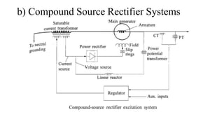
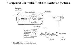
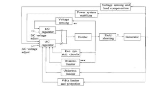
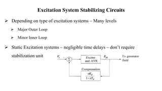
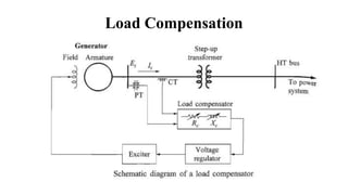
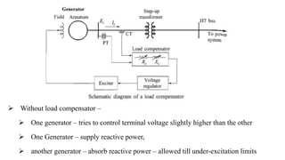
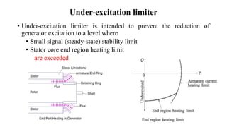
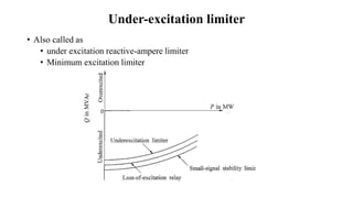
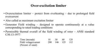
Excitation Systems
Block diagram of Synchronous Gen. Excitation System
Types of Excitation Systems
1) DC Excitation Systems
utilize a DC generator with commutator
2) AC Excitation Systems
utilize an AC generator (Alternators) with stationary or
rotating rectifiers
3) Static (Non Rotating) Excitation Systems
utilize a transformer and Rectifier
DC Excitation Systems
AC Excitation Systems
a) Stationary Rectifier Systems
b) Rotating Rectifier Systems
a) Stationary Rectifier Systems
b) Rotating Rectifier Systems
Static Excitation Systems
a) Potential Source Controlled Rectifier Systems
b) Compound Source Rectifier Systems
c) Compound Controlled Rectifier Excitation Systems
a) Potential Source Controlled Rectifier Systems
b) Compound Source Rectifier Systems
• Field Flashing of Static Exciters
Compound Controlled Rectifier Excitation Systems
Excitation System Control and
Protection Circuits
AC and DC Regulators
 AC Regulator – Maintain the generator stator voltage
 DC Regulator – holds constant generator field voltage – Manual Control
 Primarily – testing, start up and AC regulator is faulty
 Minimize voltage and reactive power excursions
 During abrupt removal of AC regulator
 Caution - During Manual control – machine should not exceed the limits
Excitation System Stabilizing Circuits
 Excitation systems – elements with significant time delays – poor inherent
dynamic performance – particularly for dc and ac type
 Excitation control – becomes unstable – generator – open circuit
 To improve dynamic performance – compensation is essential
 Compensation – minimizes the phase shift – introduced by time delays
 Results in stable offline performance
 Can also be adjusted – online performance
Excitation System Stabilizing Circuits
 Depending on type of excitation systems – Many levels
 Major Outer Loop
 Minor Inner Loop
 Static Excitation systems – negligible time delays – don’t require
stabilization unit
Power System Stabilizers
 Uses auxiliary stabilizing signals to control – excitation system –improve
power system dynamic performance.
 Input signals may be – Shaft speed, terminal frequency and power
 Damping system oscillations – dynamic performance
 Enhance small signal stability performance
Load Compensation
Load Compensation
 Automatic voltage regulator (AVR) – control – generator stator terminal
voltage.
 Load compensation – control voltage – w.r.t to voltage at a point – within or
external to the generator.
 Compensator – Adjustable resistance (Rc) and inductive reactance (Xc) –
impedance between generator terminals and the point at which the voltage
need to be controlled.
Load Compensation
 Using a) Measured Impedance, b) Current, voltage drop is computed, added or subtracted
from the terminal voltage. Compensated voltage fed to AVR
𝑉
𝑐 = 𝐸𝑡 + (𝑅𝑐+𝑗𝑋𝑐) 𝐼𝑡
 If RC & XC are positive – Terminal Voltage + Voltage drop
 Compensator regulates the voltage within the generator provides voltage droop
 Ensures power sharing reactive power between the generators
 Commonly used in hydro power plants
 Reactor power compensator – artificial coupling between the generator
 Without load compensator –
 One generator – tries to control terminal voltage slightly higher than the other
 One Generator – supply reactive power,
 another generator – absorb reactive power – allowed till under-excitation limits
Load Compensation
 When Rc and Ic are negative – regulates the voltage beyond the terminals
 Compensates the voltage drop in across the step-up transformer
 Typically 50 – 80 % of the transformer impedance is compensated
 Ensure the voltage droop – for satisfactory parallel operation of the
generators
 Also called as Line drop compensator
Under-excitation limiter
• Under-excitation limiter is intended to prevent the reduction of
generator excitation to a level where
• Small signal (steady-state) stability limit
• Stator core end region heating limit
are exceeded
Under-excitation limiter
• Also called as
• under excitation reactive-ampere limiter
• Minimum excitation limiter
Over-excitation limiter
• Overexcitation limiter – protect from overheating – due to prolonged field
overcurrent
• Also called as maximum excitation limiter
• Generator Field winding – designed to operate continuously at a value
corresponding to rated loading conditions
• Permissible thermal overall of the field winding of rotor – ANSI standard
C50.13-1977
Over-excitation limiter
• Overexcitation limiting function – detects high field current
• After a time delay – ac regulator to reduce excitation – within 100% to 110%
• Unsuccessful – trips ac regulator – change to dc regulator
• If excitation is not within safe value – limiter initiates breaker and unit trip
Over-excitation limiter
• Two types of time delays used
• Fixed time limiters
• Inverse time limiters – includes field
thermal capability
• For high ceiling voltage exciters
• Additional fault current limiter
• Acts instantaneously through ac regulator
• Limits current to short time limit (160%)
𝐸 = 4.44 ∅𝑚 f N
𝐸 = 𝑘 ∅𝑚 f
∅𝑚 = k
𝐸
𝑓
• Field voltage is controlled to control the generator terminal voltage
Volt-per-Hertz Limiter and Protection
Field Shorting Circuits
Rectifiers can’t conduct in reverse direction – ac and static exciters. Induced current is
negative under pole slipping and system short circuits – causes high voltage
• Thyristor and
• Field Discharge Resistor (FDR)
• During overvoltage – created by induced
current – not having path initially
• Non linear resistor
• Offers high resistance during normal
operation
• During overvoltage - resistance decreases
• Provides path to current flow and limits
the voltage

Excitation Systems.pptx

  • 1.
  • 2.
    Block diagram ofSynchronous Gen. Excitation System
  • 3.
    Types of ExcitationSystems 1) DC Excitation Systems utilize a DC generator with commutator 2) AC Excitation Systems utilize an AC generator (Alternators) with stationary or rotating rectifiers 3) Static (Non Rotating) Excitation Systems utilize a transformer and Rectifier
  • 4.
  • 5.
    AC Excitation Systems a)Stationary Rectifier Systems b) Rotating Rectifier Systems
  • 6.
  • 8.
  • 9.
    Static Excitation Systems a)Potential Source Controlled Rectifier Systems b) Compound Source Rectifier Systems c) Compound Controlled Rectifier Excitation Systems
  • 10.
    a) Potential SourceControlled Rectifier Systems
  • 11.
    b) Compound SourceRectifier Systems
  • 12.
    • Field Flashingof Static Exciters Compound Controlled Rectifier Excitation Systems
  • 13.
    Excitation System Controland Protection Circuits
  • 15.
    AC and DCRegulators  AC Regulator – Maintain the generator stator voltage  DC Regulator – holds constant generator field voltage – Manual Control  Primarily – testing, start up and AC regulator is faulty  Minimize voltage and reactive power excursions  During abrupt removal of AC regulator  Caution - During Manual control – machine should not exceed the limits
  • 16.
    Excitation System StabilizingCircuits  Excitation systems – elements with significant time delays – poor inherent dynamic performance – particularly for dc and ac type  Excitation control – becomes unstable – generator – open circuit  To improve dynamic performance – compensation is essential  Compensation – minimizes the phase shift – introduced by time delays  Results in stable offline performance  Can also be adjusted – online performance
  • 17.
    Excitation System StabilizingCircuits  Depending on type of excitation systems – Many levels  Major Outer Loop  Minor Inner Loop  Static Excitation systems – negligible time delays – don’t require stabilization unit
  • 18.
    Power System Stabilizers Uses auxiliary stabilizing signals to control – excitation system –improve power system dynamic performance.  Input signals may be – Shaft speed, terminal frequency and power  Damping system oscillations – dynamic performance  Enhance small signal stability performance
  • 19.
  • 20.
    Load Compensation  Automaticvoltage regulator (AVR) – control – generator stator terminal voltage.  Load compensation – control voltage – w.r.t to voltage at a point – within or external to the generator.  Compensator – Adjustable resistance (Rc) and inductive reactance (Xc) – impedance between generator terminals and the point at which the voltage need to be controlled.
  • 21.
    Load Compensation  Usinga) Measured Impedance, b) Current, voltage drop is computed, added or subtracted from the terminal voltage. Compensated voltage fed to AVR 𝑉 𝑐 = 𝐸𝑡 + (𝑅𝑐+𝑗𝑋𝑐) 𝐼𝑡  If RC & XC are positive – Terminal Voltage + Voltage drop  Compensator regulates the voltage within the generator provides voltage droop  Ensures power sharing reactive power between the generators  Commonly used in hydro power plants  Reactor power compensator – artificial coupling between the generator
  • 22.
     Without loadcompensator –  One generator – tries to control terminal voltage slightly higher than the other  One Generator – supply reactive power,  another generator – absorb reactive power – allowed till under-excitation limits
  • 23.
    Load Compensation  WhenRc and Ic are negative – regulates the voltage beyond the terminals  Compensates the voltage drop in across the step-up transformer  Typically 50 – 80 % of the transformer impedance is compensated  Ensure the voltage droop – for satisfactory parallel operation of the generators  Also called as Line drop compensator
  • 24.
    Under-excitation limiter • Under-excitationlimiter is intended to prevent the reduction of generator excitation to a level where • Small signal (steady-state) stability limit • Stator core end region heating limit are exceeded
  • 25.
    Under-excitation limiter • Alsocalled as • under excitation reactive-ampere limiter • Minimum excitation limiter
  • 26.
    Over-excitation limiter • Overexcitationlimiter – protect from overheating – due to prolonged field overcurrent • Also called as maximum excitation limiter • Generator Field winding – designed to operate continuously at a value corresponding to rated loading conditions • Permissible thermal overall of the field winding of rotor – ANSI standard C50.13-1977
  • 27.
    Over-excitation limiter • Overexcitationlimiting function – detects high field current • After a time delay – ac regulator to reduce excitation – within 100% to 110% • Unsuccessful – trips ac regulator – change to dc regulator • If excitation is not within safe value – limiter initiates breaker and unit trip
  • 28.
    Over-excitation limiter • Twotypes of time delays used • Fixed time limiters • Inverse time limiters – includes field thermal capability • For high ceiling voltage exciters • Additional fault current limiter • Acts instantaneously through ac regulator • Limits current to short time limit (160%)
  • 29.
    𝐸 = 4.44∅𝑚 f N 𝐸 = 𝑘 ∅𝑚 f ∅𝑚 = k 𝐸 𝑓 • Field voltage is controlled to control the generator terminal voltage Volt-per-Hertz Limiter and Protection
  • 30.
    Field Shorting Circuits Rectifierscan’t conduct in reverse direction – ac and static exciters. Induced current is negative under pole slipping and system short circuits – causes high voltage • Thyristor and • Field Discharge Resistor (FDR) • During overvoltage – created by induced current – not having path initially • Non linear resistor • Offers high resistance during normal operation • During overvoltage - resistance decreases • Provides path to current flow and limits the voltage