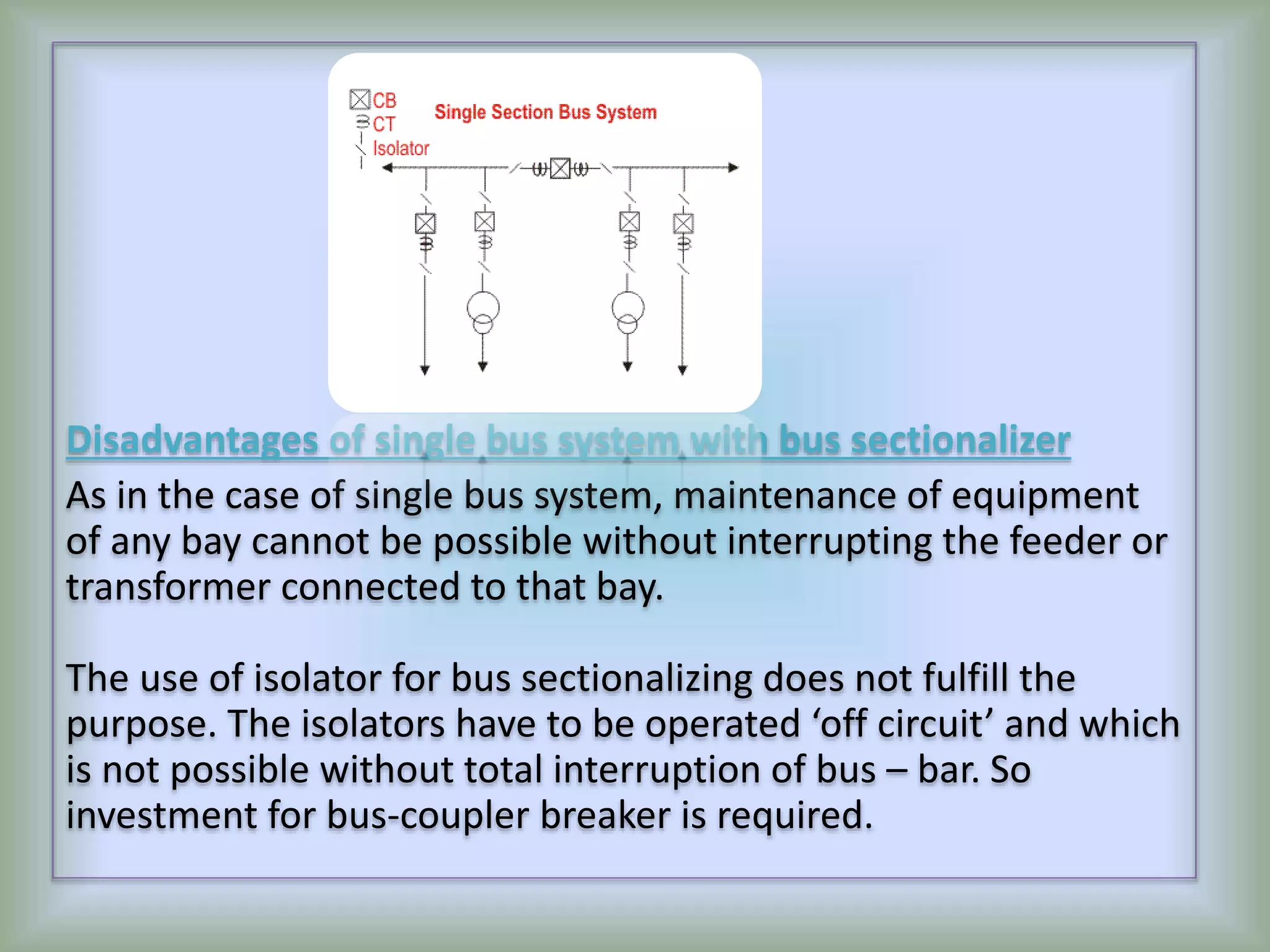
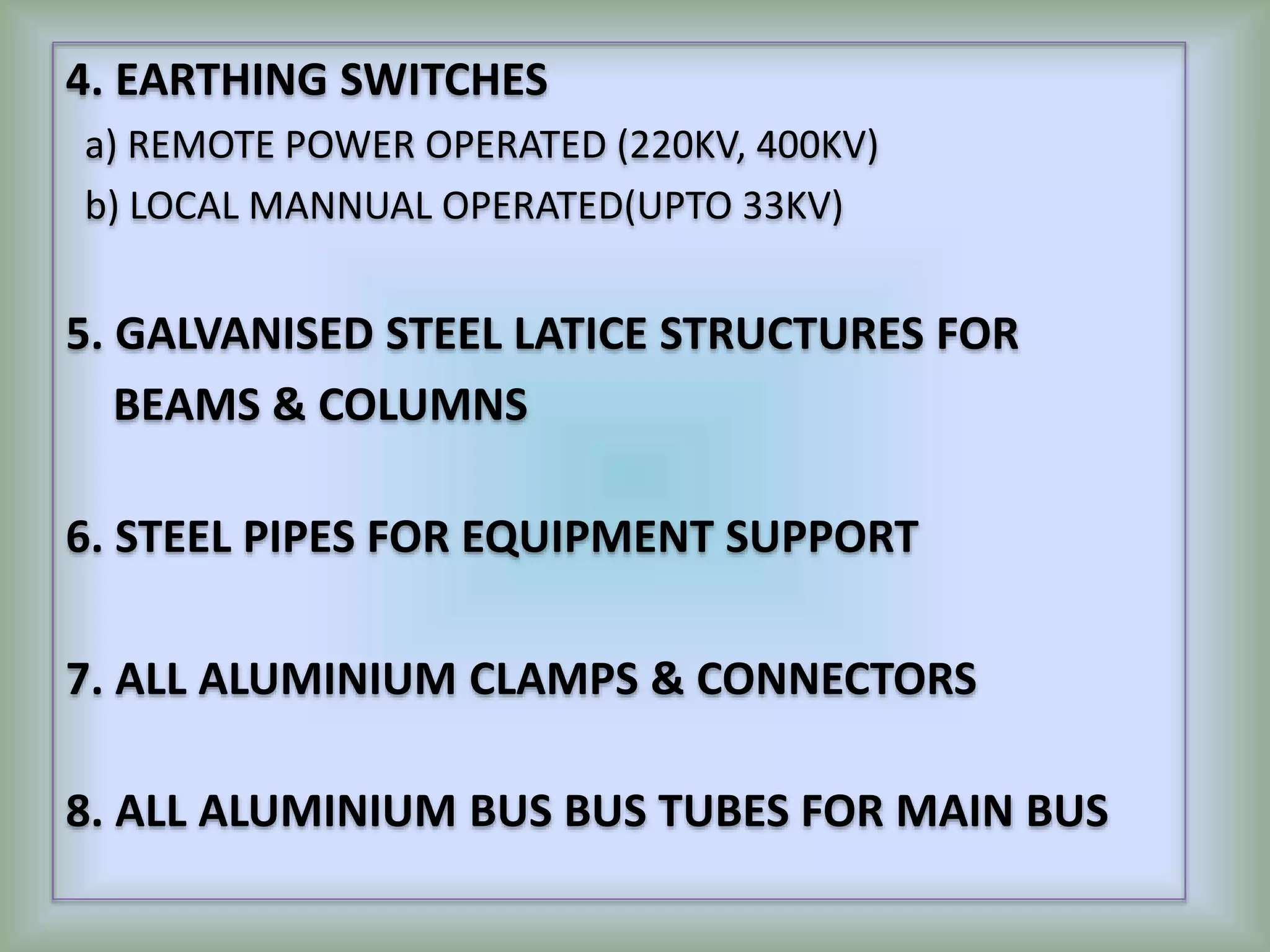
The document discusses substations, switchyards, and transmission lines. It describes different types of switchyard configurations including single bus, double bus, one and a half breaker, and gas insulated switchyards. It also discusses the major equipment found in switchyards/substations, safety procedures and minimum clearances. Maintenance procedures like routine, preventive, and breakdown maintenance are also covered. Finally, it touches on annual maintenance contracts, manufacturers, and the engineering, procurement, and construction of transmission lines.
3. 1.1 SUB-STATION
1.2 SWITCHYARD
1.3 TYPES OF SWITCHYARDS
1.3a SINGLE BUS BUS
1.3b Double bus bus
1.3c One and Half Breaker Switchyard
1.3d EHT Switchyard using GIS Switchgear
4.
5. 3.10 LIST OF MAJOR EQUIPMENT IN SUB-STATION/ SWITCHYARD/
SUBSTATION
3.11 SAFETY
3.12 I.E. RULES RELATED TO SAFETY AND MINIMUM CLEARANCES
TO BE KNOWN BEFORE ENTERING A SWITCHYARD
.
3.12 a)FOR LOW(230V TO 630V) & MEDIUM Voltage (630V TO
11000V)
Phase to Earth…5.8 MTR. Mnm.Clearance
Phase to Phase….. Mtr. Mnm. Clearances
6. 3.12 b) FOR HIGH Voltage(11kV TO 66kV) AND EXTRA HIGH
VOLTAGE (66KV TO 400KV/750KV ONWARDS…IN
INDIA
Phase to Earth= 6.1 Mtr. Mnm
Phase to Phase….. Mtr. Mnm. Clearance
3.13) WORK PERMIT FOR ATTENDING SWITCHYARD/
SUB- STATION.
3.2) MAINTENANCE OF EQUIPMENT
3.2a) ROUTINE MAINTENANCE
3.2b) PREVENTIVE MAINTENANCE
3.2c) BREAKDOWN MAINTENANCE
7. 4.1 MANUFACTURERS’ OWN AMC
4.2 LIST OF MANUFACTURER / VENDORS OF EHT
EQUIPMENT APPLYING ANNUAL MAINTENANCE
SCHEME
4.2a) M/S SIEMENS INDIA LIMITED.
4.2b) M/S ABB
4.2c) M/S ALSTHOM
11. 1.1 SUB-STATION
A HT & EHT Sub-station is a switchyard with
One or more Transformers for distribution of
Electrical power, at reduced voltages,
suitable to the network.
12. 1.2 SWITCHYARD
A Switchyard is a Nodal place where HT and
EHT POWER is brought IN and DISTRIBUTED
OUT, through different Overhead Lines and UG
Cables. A switchyard does not have any
Transformer
14. 1.3a) SINGLE BUS
Advantages of single bus system.
1) Its Very SIMPLE IN DESIGN
2) Very COST EFFECTIVE
3) Very CONVENIENT TO OPERATE
Disadvantages of single bus system
One major difficulty of these type of arrangement is that, MAINTENANACE OF
EQUIPMENT OF Any bay, CANNOT BE POSSIBLE WITHOUT INTERRUPTING THE
FEEDER, or transformer connected to that bay.
15. Single Bus System with Bus Sectionalizer
Advantages with bus sectionalizer
If any of the sources is out of system, still all loads can be fed by
switching on the sectional circuit breaker or bus coupler breaker.
If one section of the bus bar system is under maintenance, part
load of the substation can be fed by energizing the other section
of bus bar.
16. Disadvantages of single bus system with bus sectionalizer
As in the case of single bus system, maintenance of equipment
of any bay cannot be possible without interrupting the feeder or
transformer connected to that bay.
The use of isolator for bus sectionalizing does not fulfill the
purpose. The isolators have to be operated ‘off circuit’ and which
is not possible without total interruption of bus – bar. So
investment for bus-coupler breaker is required.
18. In double bus bar system two identical bus bars are used in such
a way that any outgoing or incoming feeder can be taken from
any of the bus.
Actually every feeder is connected to both of the buses in
parallel through individual isolator as shown in the figure.
19. By closing any of the isolators one can put the feeder to
associated bus. Both of the buses are energized and total
feeders are divided into two groups, one group is fed from
one bus and other from other bus. But any feeder at any
time can be transferred from one bus to other. There is one
bus coupler breaker which should be kept close during bus
transfer operation. For transfer operation, one should first
close the bus coupler circuit breaker then close the isolator
associated with the bus to where the feeder would be
transferred and then open the isolator associated with the
bus from where feeder is transferred. Lastly after this
transfer operation he or she should open the bus coupler
breaker.
20. Advantages of Double Bus System
Double Bus Bar Arrangement increases the
flexibility of system.
Disadvantages of Double Bus System
The arrangement does not permit breaker
maintenance with out interruption.
22. In double breaker bus bar system two identical bus bars are
used in such a way that any outgoing or incoming feeder can be
taken from any of the bus similar to double bus bar system.
Only difference is that here every feeder is connected to both
of the buses in parallel through individual breaker instead only
isolator as shown in the figure. By closing any of the breakers
and its associated isolators, one can put the feeder to
respective bus. Both of the buses are energized and total
feeders are divided into two groups, one group is fed from one
bus and other from other bus similar to previous case. But any
feeder at any time can be transferred from one bus to other.
There is no need of bus coupler as because the operation is
done by breakers instead of isolator. For transfer operation, one
should first close the isolators and then the breaker associated
with the bus to where the feeder would be transferred and
then he or she opens the breaker and then isolators associated
with the bus from where feeder is transferred.
24. One and a half Breaker Bus System
This is an improvement on the double breaker scheme to effect saving
in the number of circuit breakers. For every two circuits only one spare
breaker is provided. The protection is however complicated since it
must associate the central breaker with the feeder whose own breaker
is taken out for maintenance. For the reasons given under double
breaker scheme and because of the prohibitory costs of equipment
even this scheme is not much popular. As shown in the figure that it is
a simple design, two feeders are fed from two different buses through
their associated breakers and these two feeders are coupled by a third
breaker which is called tie breaker. Normally all the three breakers are
closed and power is fed to both the circuits from two buses which are
operated in parallel. The tie breaker acts as coupler for the two feeder
circuits.
During failure of any feeder breaker, the power is fed through the
breaker of the second feeder and tie breaker, therefore each feeder
breaker has to be rated to feed both the feeders, coupled by tie
breaker.
25. Advantages of One and a half Breaker Bus System
During any fault on any one of the buses, that faulty bus will be cleared
instantly without interrupting any feeders in the system since all feeders will
continue to feed from other healthy bus.
Disadvantages of One and a half Breaker Bus System
This scheme is much expensive due to investment for third breaker.
26. 1.3d) EHT SWITCHYARD USING GIS SWITCHGEAR A GIS(Gas
Insulated Sub-station/Switchyard) is normally used where
there is paucity of space and specially located in the heart of
largely populated cities with concentrated load centers.
Since the interconnections in-between CBs, Isolators, CTs,
CVTs., etc., are closely knit in a GIS, due to increased pressure
of INERT GAS(SF6) inside, there is a great reduction of power
layout space. This criterion is utilized advantageously, while
Designing the power layout, involving GIS.
28. THE TERM “TROUBLE SHOOTING” mainly
attributes to NON-CLOSURE OF “CLOSING
COIL” OR “ TRIPPING COIL” OF ALL CIRCUIT
BREAKERS OR/AND ALL REMOTE OPERATING
ISOLATORS THEREFORE, TROUBLE SHOOTING
MAINLY CONCERNS.
THE D.C. CONTROL SYSTEM (THE SOURCE OF
AUXILIARY POWER), FOR AIR BLAST TYPE, SF6 TYPE
AND VACCUM CIRCUIT BREAKERS.
29. THE INTER CONNECTIVITY OF THE PARTICULAR CIRCUIT
INCLUDING THE VARIOUS INTERLOCKING LIMIT
SWITCHES AND RELAY CONTACTS.
IN THE AIR BLAST TYPE, THE PNEUMATIC SYSTEM
INCLUDING THE COPPER TUBING AND ITS END
TERMINATIONS.
CHECK FOR SYMULTANEOUS OPEN & CLOSE OF SLOW
OPEN & CLOSE OF MAIN CONTACTS, OF CIRCUIT
BREAKERS AND ISOLATORS.
31. EHT Switchyard /Substation being in the
PRIMARY NETWORK of power distribution, it is
the most vital nodal point in the NETWORK.
RELIABILITY of POWER DISTRIBUTION, greatly
depends on these NODES.
It is therefore, very important to check and
enhance the longevity and quality of each item,
comprising these Nodes (SWITCHYARD).
32. 3.1 LIST OF MAJOR EQUIPMENT IN
SWITCHYARD/ SUBSTATION
33. 1. TRANSFORMERS
a) DRY TYPE (CAST RESIN TYPE)
b) OIL FILLED TYPE
2. CIRCUIT BREAKERS
a) AIR BLAST TYPE ( 33KV, 132KV, 220KV)
b) SF6 TYPE (220KV, 400KV )
c) VACCUM TYPE (220KV, 400KV)
3. POWER ISOLATERS
a) HORIZONTAL DOUBLE BREAK ISOLATORS (33KV,132KV)
b) HORIZONTAL CENTRE BREAK ISOLATORS (220KV, 400KV)
c) VERTICAL PANTOGRAPH ISOLATORS (220KV, 400KV)
34. 4. EARTHING SWITCHES
a) REMOTE POWER OPERATED (220KV, 400KV)
b) LOCAL MANNUAL OPERATED(UPTO 33KV)
5. GALVANISED STEEL LATICE STRUCTURES FOR
BEAMS & COLUMNS
6. STEEL PIPES FOR EQUIPMENT SUPPORT
7. ALL ALUMINIUM CLAMPS & CONNECTORS
8. ALL ALUMINIUM BUS BUS TUBES FOR MAIN BUS
35. 9. SECONDARY EMERGENCY SOURCE FOR PROVIDING.
POWER TO THE CONTROLLING SYSTEM (BATTERY,
BATTERY CHARGER, DC BOARD)
10. HORIZONTAL ISOLATORS WITH DOUBLE BREAK
(33KV)
11. VERTICAL ISOLATORS WITH DOUBLE BREAK TYPE
(33KV)
12. HORIZONTAL CENTRAL BREAK ISOLATORS
(220KV & 400KV)
36. 13. (220KV/400KV) VERTICAL BREAK PAN TO GRAPH
ISOLATORS
14. SF6 SINGLE BREAK CIRCUIT BREAKERS
(132KV,220KV)
15. SF6 DOUBLE BREAK CIRCUIT BREAKERS(400KV)
16. VACCUUM SINGLE BREAK CIRCUIT BREAKE
(132KV,220KV)
37. 17. VACUUM D0UBLE BREAK CIRCUIT BREAKER
(400KV)
18. EARTHING SWITCHES FOR 400KV HVDC
SWITCHYARDS.
19. BUS POST INSULATORS
20. MULTICORE CTs, CVTs
21. WAVE TRAPS FOR COMMUNICATION & LINE
PROTECTION
38. 22. SWITCHYARD MAIN EARTHING
23. SWITCHYARD AUXILIARY EARTHING FOR MAIN
EQPMNT.
24. SWITCHYARD LIGHTING TOWERS/MASTS
25. LIGHTENING PROTECTION SCHEMES OF
SWITCHYARD
39. 26. 2 No’s of 30 KVA UPS BACK TO BACK, With
minimum 20 minutes battery Back-up. The
Emergency Back-up should be essentially connected
to at least 25% of the Lighting System of the
CONTROL ROOM, Video Conference Room, Main
and Half Landing of Stair cases, Walking corridor,
Toilets, Flashing Exit Lights, etc.
40. 3.11 SAFETY
MAINTAIN SAFETY OF PERSONNEL AND EQUIPMENTAT
ANY COST SAFETY RULES SHOULD BE FOLLOWED
RELIGIOUSLYAND SEQUENTIALLY TO AVOID ACCIDENT/
ELECTROCUTION.
41. 3.12 I.E. RULES RELATED TO SAFETY AND MINIMUM
CLEARANCES TO BE KNOWN BEFORE ENTERING A
SWITCHYARD.
a) FOR LOW(230V TO 630V) & MEDIUM Voltage
(630V TO 11000V)
Phase to Earth…5.8 MTR. Mnm.Clearance
Phase to Phase….. Mtr. Mnm. Clearance
B) FOR HIGH Voltage AND EXTRA HIGH VOLTAGE
Phase to Earth= 6.1 Mtr.Mnm.Clearance
Phase to Phase….. Mtr. Mnm. Clearance
42. 3.13) WORK PERMIT FOR ATTENDING SWITCHYARD/
SUB- STATION.
ISSUE of WORK PERMIT / RETURN of WORK-PERMIT.
This is a very IMPORTANT DOCUMENT and the person who
issues / accepts it, should be a RESPONSIBLE Person, not less
than the rank of a SUPERINTENDENT ENGINEER from
OPERATION & MAINTENANCE GROUP.
43.
44. 1) SWITCH OFF the Concerned feeders.
2) ISOLATE the Feeders.
3) Remove and keep the Controlling Fuses in safe
custody.
4) Inspect all the accessible BUS SHUTTERS TO BE
CLOSED and PADLOCKED.
5) ISSUE the WORK PERMIT, BY NAME OF THE PERSON
WHO TAKES IT, mentioning all these important
activities.
45. 6) Apply local EARTHING BY SHORTING EARTHING ALL
THE PHASES. After COMPLETION of all work, the safety
devices and all shortings and EARTHINGS ARE
REMOVED AND THE WORK PERMIT is returned. Again
as a precautionary method, the same person who took
the WORK PERMIT, SHOULD RETURN IT’.
47. 4.0 ANNUAL MAINTENANCE CONTRACT
Any Switchyard being upstream in the loadflow diagram,
anything and everything in a switchyard, is very critical. An
outage due to malfunctioning of any item, is disastrous.
Like all other equipment, a procedural Format is followed
by the manufacturers, to generate a list of various parts of
all the Equipment, erected in a Switchyard.
These parts and their sub-parts are codifiedand identified
individually and madecompatible to SAP.
An inventory of all these items aremeticulously maintained,
so that in the event of an outage, downtime shall be
minimum.
48. 4.1 MANUFACTURERS’ OWN AMC
4.2 LIST OF MANUFACTURER / VENDORS OF EHT
EQUIPMENT APPLYING ANNUAL MAINTENANCE
SCHEME
4.2a) M/S SIEMENS INDIA LIMITED
4.2b) M/S ABB
4.2c) M/S ALSTHOM
49. 5.0 DIFERENT TYPES ( A,B,C,D & SPECIAL TYPE)
OF TOWERS FOR TRANSMISSION LINES.
50. In order to build up a Transmission Line, keeping within
the allocated power corridor, various types of TOWERS
are used. These are :-
a) (TYPE) Tangent Tower..( max deviation from TOWER
Centre Line being 0to5 Degrees)
b) (TYPE)…Angular Tower…(max Deviation 5 to15
degrees).
c) (TYPE)…Angular Tower…(15 to 30 degrees).
d) (TYPE)…Angular Tower…( 30 to 60 degrees)
51. SPECIAL TYPES OF TOWERS.. (60 to 90 degrees).
TERMINATION OF OVERHEAD EHT
TRANSMISSION LINES ON TO THE
SWITCHYARD GANTRIES
XXXXXXXXXXXXXXXXXXXXXXXXXXXXXXXXXXXXXX
53. 6.0 BASIC STEPS TAKEN FOR ENGINEERING,
PROCUREMENT & CONSTRUCTION OF EHT
TRANSMISSION LINES
54. 6.1 ROUTE SURVEYING
(WALK THROUGH SURVEY)
As the name suggests, the WALK THROUGH SURVEY, is a
very informative survey and determines the nature of the
PROJECT, as per points appended :
55. 1. The existing contours above Finished Ground Level
and within the pre-defined route, as per the
GOVERNMENT NOTIFICATION put –up in the local
GAZETTE, are carefully noted, studied and finally
fixed, keeping in mind TOWER SPOTTING
LOCATIONS & THE MINIMUM GROUND
CLEARANCES THAT SHALL BE REQUIRED, as per I.E.
Rules.
2. Any existing water-fronts which are to be
encountered
56. 3. Any SHORING required for the Tower foot near
water-fronts.
4. Any BENCHING required while crossing, hills.
57. 6.2 TOWER SPOTTING (MAINTAINING
MINIMUM CLEARANCES).
As per the span available on both sides, of any Tower,
the particular SPOT of the next Towers are fixed,
keeping in mind if any SHORING / BENCHING is
required or not.
58. 6.3 ALLOCATING TYPE OF TOWER TO BE USED,
MAINTAIN SAG, TENSION & MINIMUM
CLEARANCES AS PER I.E. RULES & ACTS.
Once the TOWER SPOTS are fixed, the Type of Tower
(A,B,C,D,Special) ,required for the situation is finally
frozen.