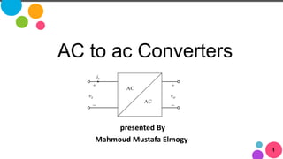
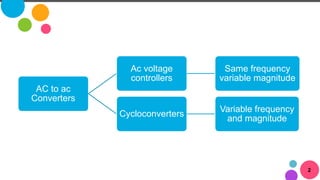
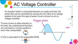
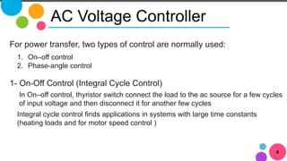
1
AC to ac Converters
presented By
Mahmoud Mustafa Elmogy
2
AC to ac
Converters
Ac voltage
controllers
Same frequency
variable magnitude
Cycloconverters
Variable frequency
and magnitude
3
AC Voltage Controller
If a thyristor switch is connected between ac supply and load, the
power flow can be controlled by varying the rms value of ac voltage
applied to the load; this type of power circuit is known as an ac
voltage controller.
naturally commutated (AC)
To have current in either direction in
the load, two unidirectional thyristors
are connected in inverse parallel to
each other (antiparallel)
A Triac is equivalent to the antiparallel SCRs
4
AC Voltage Controller
For power transfer, two types of control are normally used:
1. On–off control
2. Phase-angle control
1- On-Off Control (Integral Cycle Control)
In On–off control, thyristor switch connect the load to the ac source for a few cycles
of input voltage and then disconnect it for another few cycles
Integral cycle control finds applications in systems with large time constants
(heating loads and for motor speed control )
5
On-Off Control (Integral Cycle Control)
6
On-Off Control (Integral Cycle Control)
RMS value of output voltage is
Where
D is called the duty cycle
D = n / (m + n) = Ton / T
7
Phase-angle control (Single-phase)
Resistive Load
In phase control, thyristor switches connect the load to the ac source for a
portion of each cycle of input voltage
8
Single-Phase Controller with a Resistive Load
Note that for alpha=0, the load voltage is a sinusoid that has the same rms value as the source.
9
Single-Phase Controller with RL Load
RL Load
10
Three -phase Voltage Controllers
Y-Connected Resistive Load
The firing sequence of thyristors is
T1, T2, T3, T4, T5, T6.
When three SCRs are on (one in each
phase): The voltage across each
phase of the load is the corresponding
line-to-neutral voltage
When two SCRs are on: the line-to-
line voltage of those two phases is
equally divided between the two load
resistors that are connected
Which SCRs are conducting depends on the delay angle α and on the source
voltages at a particular instant
11
Three -phase Voltage Controllers
For 0 < α < 60 :
Two or three SCRs conduct at any one time
for this range of
For 60 < α < 90 :
Only two SCRs conduct at any one time
For 90 < α < 150 :
Only two SCRs can conduct at any one
time in this mode. Additionally, there are
intervals when no SCRs conduct.
For α > 150 :
No SCRs conduct. Output voltage is zero
for this condition.
12
Applications
STATIC VAR CONTROL
The circuit shown represents an application of an ac
voltage controller to maintain a unity power factor
for varying load VAR requirements. The power
factor correction capacitance supplies a fixed
amount of reactive power. The parallel inductance
absorbs a variable amount of reactive power,
depending on the delay angle of the SCRs. As the
VAR requirement of the load changes, the delay
angle is adjusted to maintain unity power factor.
Static VAR control has the advantage of being able to adjust to changing load
requirements very quickly.
The SCRs are placed in the inductor branch rather than in the capacitor branch because very high
currents could result from switching a capacitor with a SCR.
13
Cycloconverters
A cycloconverter is a direct-frequency changer that converts ac power at one frequency
to ac power at another frequency by ac–ac conversion, without an intermediate
conversion link
The majority of cycloconverters are naturally commutated and the maximum output
frequency is limited to a value that is only a fraction of the source frequency(step down).
• Single-phase to single-phase cycloconverters
• Three-phase to single-phase cycloconverters
• Three-phase to three-phase cycloconverters
Step-down cycloconverter circuits can be further classified into following types.
14
Cycloconverters
single-phase to single-phase cycloconverters
The two single-phase controlled
converters are operated as bridge
rectifiers
cycloconverter output voltage can be varied by applying phase control technique
15
Cycloconverters
Three-phase to single-phase cycloconverter
cycloconverter output voltage can be varied by applying phase control technique
The two ac–dc converters are three-
phase controlled rectifiers.
16
Cycloconverters
Three-phase to Three-phase cycloconverter
Three-phase/single-phase cycloconverter can be extended to provide three-phase output
by having 6 three-phase converters, as shown
17
References
Books
1. Muhammad H. Rashid, “Power Electronics: Devices, Circuits, and
Applications’’ Prentice-Hall, 2014.
2. Daniel W. Hart, “Power Electronics”, McGraw-Hill, 2011.
Lecture Notes
Eladl A, Power electronics 2, AC Voltage Controllers, Lecture Notes,
Mansoura univ, 2020
Thank you

AC to ac Converters.pptx

  • 1.
    1 AC to acConverters presented By Mahmoud Mustafa Elmogy
  • 2.
    2 AC to ac Converters Acvoltage controllers Same frequency variable magnitude Cycloconverters Variable frequency and magnitude
  • 3.
    3 AC Voltage Controller Ifa thyristor switch is connected between ac supply and load, the power flow can be controlled by varying the rms value of ac voltage applied to the load; this type of power circuit is known as an ac voltage controller. naturally commutated (AC) To have current in either direction in the load, two unidirectional thyristors are connected in inverse parallel to each other (antiparallel) A Triac is equivalent to the antiparallel SCRs
  • 4.
    4 AC Voltage Controller Forpower transfer, two types of control are normally used: 1. On–off control 2. Phase-angle control 1- On-Off Control (Integral Cycle Control) In On–off control, thyristor switch connect the load to the ac source for a few cycles of input voltage and then disconnect it for another few cycles Integral cycle control finds applications in systems with large time constants (heating loads and for motor speed control )
  • 5.
  • 6.
    6 On-Off Control (IntegralCycle Control) RMS value of output voltage is Where D is called the duty cycle D = n / (m + n) = Ton / T
  • 7.
    7 Phase-angle control (Single-phase) ResistiveLoad In phase control, thyristor switches connect the load to the ac source for a portion of each cycle of input voltage
  • 8.
    8 Single-Phase Controller witha Resistive Load Note that for alpha=0, the load voltage is a sinusoid that has the same rms value as the source.
  • 9.
  • 10.
    10 Three -phase VoltageControllers Y-Connected Resistive Load The firing sequence of thyristors is T1, T2, T3, T4, T5, T6. When three SCRs are on (one in each phase): The voltage across each phase of the load is the corresponding line-to-neutral voltage When two SCRs are on: the line-to- line voltage of those two phases is equally divided between the two load resistors that are connected Which SCRs are conducting depends on the delay angle α and on the source voltages at a particular instant
  • 11.
    11 Three -phase VoltageControllers For 0 < α < 60 : Two or three SCRs conduct at any one time for this range of For 60 < α < 90 : Only two SCRs conduct at any one time For 90 < α < 150 : Only two SCRs can conduct at any one time in this mode. Additionally, there are intervals when no SCRs conduct. For α > 150 : No SCRs conduct. Output voltage is zero for this condition.
  • 12.
    12 Applications STATIC VAR CONTROL Thecircuit shown represents an application of an ac voltage controller to maintain a unity power factor for varying load VAR requirements. The power factor correction capacitance supplies a fixed amount of reactive power. The parallel inductance absorbs a variable amount of reactive power, depending on the delay angle of the SCRs. As the VAR requirement of the load changes, the delay angle is adjusted to maintain unity power factor. Static VAR control has the advantage of being able to adjust to changing load requirements very quickly. The SCRs are placed in the inductor branch rather than in the capacitor branch because very high currents could result from switching a capacitor with a SCR.
  • 13.
    13 Cycloconverters A cycloconverter isa direct-frequency changer that converts ac power at one frequency to ac power at another frequency by ac–ac conversion, without an intermediate conversion link The majority of cycloconverters are naturally commutated and the maximum output frequency is limited to a value that is only a fraction of the source frequency(step down). • Single-phase to single-phase cycloconverters • Three-phase to single-phase cycloconverters • Three-phase to three-phase cycloconverters Step-down cycloconverter circuits can be further classified into following types.
  • 14.
    14 Cycloconverters single-phase to single-phasecycloconverters The two single-phase controlled converters are operated as bridge rectifiers cycloconverter output voltage can be varied by applying phase control technique
  • 15.
    15 Cycloconverters Three-phase to single-phasecycloconverter cycloconverter output voltage can be varied by applying phase control technique The two ac–dc converters are three- phase controlled rectifiers.
  • 16.
    16 Cycloconverters Three-phase to Three-phasecycloconverter Three-phase/single-phase cycloconverter can be extended to provide three-phase output by having 6 three-phase converters, as shown
  • 17.
    17 References Books 1. Muhammad H.Rashid, “Power Electronics: Devices, Circuits, and Applications’’ Prentice-Hall, 2014. 2. Daniel W. Hart, “Power Electronics”, McGraw-Hill, 2011. Lecture Notes Eladl A, Power electronics 2, AC Voltage Controllers, Lecture Notes, Mansoura univ, 2020
  • 18.