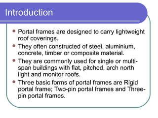
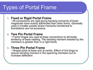
Portal Frame Design
Introduction
 Portal frames are designed to carry lightweight
roof coverings.
 They often constructed of steel, aluminium,
concrete, timber or composite material.
 They are commonly used for single or multi-
span buildings with flat, pitched, arch north
light and monitor roofs.
 Three basic forms of portal frames are Rigid
portal frame; Two-pin portal frames and Three-
pin portal frames.
Introduction
Refer to notes to:
http://en-gb.facebook.com/note.php?note_id=298379392385
Types of Portal Frame
1. Fixed or Rigid Portal Frame
- All connections are rigid giving bending moments of lower
magnitude more evenly distributed than other forms. Generally
used in smaller portals where moments transferred to
foundations are not excessive.
2. Two Pin Portal Frame
- Frame hinges are used at base connections to eliminate
tendency of base rotating. The bending moment resisted by the
members is greater than in a rigid frame
3. Three Pin Portal Frame
- Hinged joints at base and at centre. Effect of 3rd hinge to
reduce bending moment in the spanning members but to
increase deflection
Benefit of Portal Frame
Can economically enclose a large area
Floor areas unrestricted by long runs of
walls, more flexible in use
Good floor to ceiling heights
Frame quicker to build than walls saving
time and money
Factors influence wind loading
 Geographical location – Malaysia, London, KL, Perlis,
etc…
 Physical location – city, small town,etc…
 Topography – hill, valley, slope area, etc..
 Altitude – height above mean sea level
 Building shape – square, rectangular, irregular, etc…
 Roof pitch – shallow, steep, mono-pitch, multi-bay,
etc..
 Building dimensions
 Wind speed and direction
 Wind peak factor
Refer to CP3: Chapter V: Part 2: 1972
Loading case for frame
Consider 3 case for frame:
Max Load = 1.4 Gk + 1.6 Qk
Min Load = 1.0 Gk
Case 1: Max, max, Max
Case 2: Max, min, Max
Case 3: Min, max, Min
Portal frame analysis and design
Analysed either by assuming linear
elastic behavior or by basing the
analysis on the basic principles of plastic
theory.
Plastic desinged frames are lighter than
elastically designed frames, however
higher stability bracing and check will
needed,
Example calculation:
Example 17-1
(handout)
Example calculation:
Example 17-1
(handout)

Portal frame by Rhythm Murgai

  • 1.
  • 2.
    Introduction  Portal framesare designed to carry lightweight roof coverings.  They often constructed of steel, aluminium, concrete, timber or composite material.  They are commonly used for single or multi- span buildings with flat, pitched, arch north light and monitor roofs.  Three basic forms of portal frames are Rigid portal frame; Two-pin portal frames and Three- pin portal frames.
  • 3.
    Introduction Refer to notesto: http://en-gb.facebook.com/note.php?note_id=298379392385
  • 4.
    Types of PortalFrame 1. Fixed or Rigid Portal Frame - All connections are rigid giving bending moments of lower magnitude more evenly distributed than other forms. Generally used in smaller portals where moments transferred to foundations are not excessive. 2. Two Pin Portal Frame - Frame hinges are used at base connections to eliminate tendency of base rotating. The bending moment resisted by the members is greater than in a rigid frame 3. Three Pin Portal Frame - Hinged joints at base and at centre. Effect of 3rd hinge to reduce bending moment in the spanning members but to increase deflection
  • 5.
    Benefit of PortalFrame Can economically enclose a large area Floor areas unrestricted by long runs of walls, more flexible in use Good floor to ceiling heights Frame quicker to build than walls saving time and money
  • 6.
    Factors influence windloading  Geographical location – Malaysia, London, KL, Perlis, etc…  Physical location – city, small town,etc…  Topography – hill, valley, slope area, etc..  Altitude – height above mean sea level  Building shape – square, rectangular, irregular, etc…  Roof pitch – shallow, steep, mono-pitch, multi-bay, etc..  Building dimensions  Wind speed and direction  Wind peak factor Refer to CP3: Chapter V: Part 2: 1972
  • 7.
    Loading case forframe Consider 3 case for frame: Max Load = 1.4 Gk + 1.6 Qk Min Load = 1.0 Gk Case 1: Max, max, Max Case 2: Max, min, Max Case 3: Min, max, Min
  • 8.
    Portal frame analysisand design Analysed either by assuming linear elastic behavior or by basing the analysis on the basic principles of plastic theory. Plastic desinged frames are lighter than elastically designed frames, however higher stability bracing and check will needed,
  • 9.
  • 10.