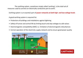
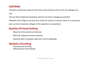
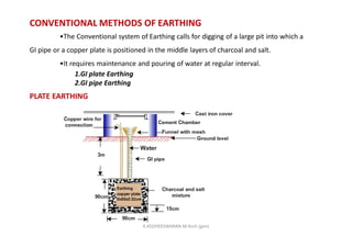
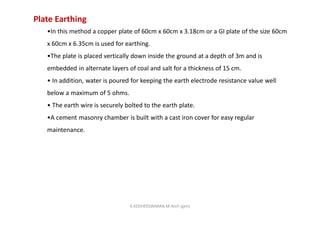
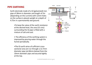
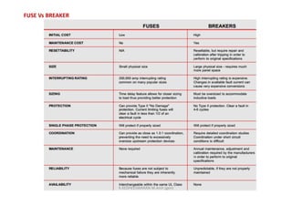
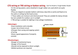
BUILDING SERVICES-II (ELECTRICAL)
K.KEDHEESWARAN M.Arch (gen)
Asst-Prof.Anna-university 2013 regulation
K.KEDHEESWARAN M.Arch (gen)
BASICS OF ELECTRICITY
At a constant temperature, the steady current flowing through a conductor is directly
proportional to the potential difference between the two ends of the conductor.
V-Voltage
I-Current
Ohm’s Law
It is defined as the velocity with which free electrons get drifted towards the
positive terminal, when an electric field is applied.
Drift velocity
Electric current
The current is defined as the rate of flow of charges across any cross sectional
area of a conductor.
K.KEDHEESWARAN M.Arch (gen)
The opposition that a material presents to the flow of electrical charges is called
resistance.
The unit for electrical resistance is the ohm (Ώ).
An increase in voltage causes an increase in current. A decrease in voltage will cause a
decrease in current, if the resistance remains the same
The current (I) drawn from a power source by a conductor will depend on the voltage (V)
of the power source, and on the properties of the conductor.
The ratio between V and I is called the resistance of that conductor. The SI unit of
resistance R is the ohm, whose symbol is Ώ
R-Resistance
V-Voltage
I-Current
The intensity of the power source is called voltage, or the potential difference between the
electrodes.
BASICS OF ELECTRICITYK.KEDHEESWARAN M.Arch (gen)
By definition, if the final energy of that one coulomb test charge is one joule. the
voltage of the power source is one volt.
The letter that symbolizes volts is V. The voltage in volts is equal to the final energy
in joules of that one coulomb test charge
Resistance and resistivity
The value of the resistance R depends on the
-material of the conductor.
-on its geometry.
-slightly on its temperature.
-the resistance increases with temperature.
KIRCHHOFF’S LAWS
-Also called Kirchhoff’s current law, states that” the algebraic sum of currents
entering and leaving any point in a circuit is equal to zero”.
The first law
Ia - Ib = 0
BASICS OF ELECTRICITYK.KEDHEESWARAN M.Arch (gen)
The algebraic sum of all voltages around a closed loop equals zero
SECOND LAW IS KIRCHHOFF’S VOLTAGE LAW
-A loop is a path so a closed loop is a closed path or complete electronic circuit.
-As current passes through a resistor then a voltage is produced.
BASICS OF ELECTRICITYK.KEDHEESWARAN M.Arch (gen)
CABLES AND WIREK.KEDHEESWARAN M.Arch (gen)
INTRODUCTION TO WIRES
There are mainly 6 types of wires are there.
 Vulcanised Indian rubber wire (V.I.R)
 Tough rubber sheathed wire (T.R.S)
 Poly vinyl chloride wire (P.V.C.)
 Lead alloy sheathed wire
 Weather proof wires
 Flexible wire
CABLES AND WIREK.KEDHEESWARAN M.Arch (gen)
V.I.R (Vulcanised Indian Rubber)
wires.
A VIR wire mainly consists of a tinned conductor having
rubber coating.
Tinning of conductor prevents the sticking of rubber to the
conductor.
Thickness of rubber mainly depends on the operating voltage
to which wire is designed.
A cotton bradding is done over the rubber insulations to
protect the conductor against the moisture.
Finally the wire is finished with wax for cleanliness.
Nowadays these wires are not used since a better quality
wires are available at a cheaper rate.
CABLES AND WIREK.KEDHEESWARAN M.Arch (gen)
T.R.S. (Tough Rubber Sheathed)
wires.
This type of wire is a modification of V.I.R. wire. It
consist of the ordinary rubber coated conductors with
an additional sheath of tough rubber.
This layer provides better protection against moisture
and wear and tear. Also it provides an extra insulation.
These wires are generally available in single
conductor, two conductors or three conductors.
CABLES AND WIREK.KEDHEESWARAN M.Arch (gen)
P.V.C. (Poly Vinyl Chloride) wires.
This is the most commonly used wire for wiring
purpose.
Conductor is insulated by poly vinyl chloride
(insulating material).
P.V.S. has following properties:
1. Moisture proof.
2.Tough.
3.Durable.
4.Chemically inert.
But it softens at high temperatures therefore not
suitable for connection to heating appliances.
CABLES AND WIREK.KEDHEESWARAN M.Arch (gen)
Lead alloy sheathed wires.
The ordinary wires can be used only at dry places but
for damp places these wires are covered with
continuous lead sheaths.
The layer of lead covering is very thin like 0.12 cm
thick.
These wires provides little mechanical protections to
the wires.
CABLES AND WIREK.KEDHEESWARAN M.Arch (gen)
Weather proof wires.
These types of wires are used outdoor i.e. providing a
service connection from overhead line to building etc.
In this type of wire the conductor is not tinned and the
conductor is covered with three braids of fibrous yarn and
saturated with water proof compound.
K.KEDHEESWARAN M.Arch (gen)
These wires consists of number of strands instead of a single conductor. (Strand is a very
thin conductor).
The conductor is insulated with P.V.C. material.
These wires are very useful for household portable appliances where flexibility of wire is
more important.
Typical specifications
55/.01mm(55 strands of 0.1mm diameter), maximum current 6A,used for household
purposes.
Flexible wires.
K.KEDHEESWARAN M.Arch (gen)
INRODUCTION TO CABLES.
A power cable is an assembly of two or more
electrical conductors, usually held together with
an overall sheath. The assembly is used for
transmission of electrical power. Power cables
may be installed as permanent wiring within
buildings, buried in the ground, run overhead,
or exposed.
Flexible power cables are used for portable
devices, mobile tools and machinery.
K.KEDHEESWARAN M.Arch (gen)
1. Conductor or Core.
2. Insulation.
3. Metallic Sheath.
4. Bedding.
5. Armouring.
6. Serving.
K.KEDHEESWARAN M.Arch (gen)
The types of cables basically
decided based on the voltage
level for which it is manufactured
and material used for the insulation
such as paper,cotton,rubber etc. the
classification of cables according to
the voltage levels is,
 Low Tension Cables (L.T. Cables).
Medium and High tension Cables
(H.T. Cables).
K.KEDHEESWARAN M.Arch (gen)
BELTED CABLES.
These cables are used for the
voltage level up to 11 kV. The
construction of belted cable is
is shown in fig.
The cores are not in circular
shape.
The cores are insulated from
each other by use of impregnated
paper.
The gaps are filled with fibrous
material like jute.
The belt is covered with lead
sheath.
K.KEDHEESWARAN M.Arch (gen)
SUPER TENSION (S.T.) CABLES.
The S.T. cables are intended for
132 kV to 25 kV voltage levels.
In such cables, the following
methods are specially used to
eliminate the possibility of
void formation:
Instead of solid type insulation,
low viscosity oils under pressure
is used for impregnation.
Using inert gas at high pressure in
b/w the lead sheath & dielectric.
K.KEDHEESWARAN M.Arch (gen)
OIL FILLED CABLES
In case of oil filled cables, the
channels or ducts are provided
within or adjacent to the cores,
through which oil under pressure
is circulated.
It consists of concentric standard
conductor but built around a hallow
cylindrical steel spiral core, which
acts as a channel for oil.
K.KEDHEESWARAN M.Arch (gen)
Cable Structure.
K.KEDHEESWARAN M.Arch (gen)
GAS PRESSURE CABLES
An inert gas like N at high pressure
is introduced lead sheath and
dielectric.
Gas like SF6 is also used in
cables.
Pressure is about 12-15
atmosphere.
Working power factors is
also high.
K.KEDHEESWARAN M.Arch (gen)
The earthing system, sometimes simply called ‘earthing’, is the total set of
measures used to connect an electrically conductive part to earth.
EARTHING
Earthing system is an essential part of power networks at both high- and low-voltage levels
A good earthing system is required for:
• Protection of buildings and installations against lightning
• Safety of human and animal life by limiting touch and step voltages to safe values
• Electromagnetic compatibility (EMC) i.e. limitation of electromagnetic disturbances
• Correct operation of the electricity supply network and to ensure good power quality
K.KEDHEESWARAN M.Arch (gen)
EARTHING
•Provide an alternative path for the fault current to flow so that it will not endanger the
user
•Ensure that all exposed conductive parts do not reach a dangerous potential
•Maintain the voltage at any part of an electrical system at a known value so as to prevent
over current or excessive voltage on the appliances or equipment.
Qualities Of Good Earthing
•Must be of low electrical resistance
•Must be of good corrosion resistance
•Must be able to dissipate high fault current repeatedly
Methods of Earthing
•Conventional Earthing
•Maintenance Free Earthing
K.KEDHEESWARAN M.Arch (gen)
CONVENTIONAL METHODS OF EARTHING
•The Conventional system of Earthing calls for digging of a large pit into which a
GI pipe or a copper plate is positioned in the middle layers of charcoal and salt.
•It requires maintenance and pouring of water at regular interval.
1.GI plate Earthing
2.GI pipe Earthing
PLATE EARTHING
K.KEDHEESWARAN M.Arch (gen)
Plate Earthing
•In this method a copper plate of 60cm x 60cm x 3.18cm or a GI plate of the size 60cm
x 60cm x 6.35cm is used for earthing.
•The plate is placed vertically down inside the ground at a depth of 3m and is
embedded in alternate layers of coal and salt for a thickness of 15 cm.
• In addition, water is poured for keeping the earth electrode resistance value well
below a maximum of 5 ohms.
• The earth wire is securely bolted to the earth plate.
•A cement masonry chamber is built with a cast iron cover for easy regular
maintenance.
K.KEDHEESWARAN M.Arch (gen)
PIPE EARTHING
Earth electrode made of a GI (galvanized) iron
pipe of 38mm in diameter and length of 2m
(depending on the current) with 12mm holes
on the surface is placed upright at a depth of
4.75m in a permanently wet ground.
•To keep the value of the earth resistance
at the desired level, the area (15 cms)
surrounding the GI pipe is filled with a
mixture of salt and coal.
• The efficiency of the earthing system is
improved by pouring water through the
funnel periodically.
•The GI earth wires of sufficient cross-
sectional area are run through a 12.7mm
diameter pipe (at 60cms below) from the
19mm diameter pipe and secured tightly
at the top.
K.KEDHEESWARAN M.Arch (gen)
SYSTEM CLASSIFICATION
1 - TT systems
2 - TN-S system
3 - TN-C-S system
4 - TN-C system
5 - IT system
The first letter indicates the type of supply earthing.
T -indicates that one or more points of the Supply are directly
earthed (for example, the earthed neutral at the transformer).
I -indicates either that the supply system is not earthed at all, or
that the earthing includes a deliberately-inserted impedance, the
purpose of which is to limit fault current. This method is not used
for public supplies in the UK.
The second letter indicates the earthing arrangement in the
installation.
T - all exposed conductive metalwork is connected directly to earth.
N - all exposed conductive metalwork is connected directly to an
earthed supply conductor provided by the Electricity Supply
Company.
The third and fourth letters indicate the arrangement of the
earthed supply conductor system.
S - neutral and earth conductor systems are quite separate.
C - neutral and earth are combined into a single conductor.K.KEDHEESWARAN M.Arch (gen)
In a TT earthing system, the protective earth
connection of the consumer is provided by a local connection
to earth, independent of any earth connection at the
generator.
The big advantage of the TT earthing system is the fact that it
is clear of high and low frequency noises that come through
the neutral wire from various electrical equipment connected
to it. This is why TT has always been preferable for special
applications like telecommunication sites that benefit from the
interference-free earthing. Also, TT does not have the risk of a
broken neutral.
In a TN earthing system, one of the points in the generator or transformer is connected
with earth, usually the star point in a three-phase system. The body of the electrical device
is connected with earth via this earth connection at the transformer.
The conductor that connects the exposed
metallic parts of the consumer is called
protective earth three-phase system
K.KEDHEESWARAN M.Arch (gen)
TN−S
PE and N are separate conductors that are connected together only near the
power source. This arrangement is the current standard for most residential
and industrial electric systems in North America and Europe.
3-TN−C
A combined PEN conductor fulfills the functions of both a PE and an N conductor. Rarely
used
Protective multiple earthing (PME), because of the practice of connecting the
combined neutral-and-earth conductor to real earth at many locations, to reduce the risk of
broken neutrals - with a similar system in Australia being designated as multiple earthed
neutral (MEN).
TYPES OF EARTHING SYSTEM:
In industrial installations, where both electrical and instrumentation equipment
are incorporated and installed, three types of earthing system
 Electrical earthing systems
 Instrument earthing systems
 Lightning earthing system
K.KEDHEESWARAN M.Arch (gen)
The earthing system, which is designed, installed and connected to all electrical
machineries and equipment as well as the plant’s bulk equipment is called the “Electrical
earthing system” or “Electrical earthing network”..
1. The overall earthing resistance of the electrical earthing system should not be greater
than 4 OHM, no matter which point of the grid is put under measurement.
2. In earthing systems, where bare conductors of the earthing grid is buried directly
underground, each section of the underground grid actually acts as an individual earth well,
parallel to the existing earth wells, thus contributing in reduction and improvement of the
overall earthing resistance.
3. Earthing connections made to the marshalling earth buses, equipment’s earth bosses etc.
should be carried out with such skill and workmanship to prevent any possible
misconnections, which could lead to added earth resistance other than established and
required.
ELECTRICAL EARTHING SYSTEMS
K.KEDHEESWARAN M.Arch (gen)
Instrument Earthing Systems
In an industrial installation with sophisticated power and electronic equipment,
protective measures should be taken to safeguard the instrumentation and the relevant
control panels against the sudden high voltages which might hit the earthing system in the
event of a fault (short-circuit) in the power circuit of the installation….
1. Sufficient distance should be maintained between the instrument earth wells and the
electrical earth wells. Standard distance is at least twice that of the greatest length of
the earth rod driven in either the instrument or the electrical well.
2. Separate earthing marshalling points (Marshalling buses) is defined and installed to be
used for independent connections to instrument devices.
3. Instrument earth buses are generally installed inside the control building where the
instrumentation control are installed and centralized.
4. The metal clad body of the instrument panels, particularly those which accommodate
the power supply line, should be connected to the electrical earth system.
5. Instrumentations installed inside the plant, shall be connected to the instrument earthing
system via the shield wires of the corresponding instrument cables.
6. Instrument earth wells are installed adjacent to the control buildingK.KEDHEESWARAN M.Arch (gen)
Electrical systems
•Basic of electricity
•Single/three phase supply
•Protective devices in electrical installation
•Earthing for safety – types of earthing
• ISI specifications.
• Electrical installations in buildings – types of wires
•Wiring systems and their choice
•Planning electrical wiring for building
•Main and distribution boards
Electrical layout
–simple residential
–school
–commercial building
ELECTRICAL SUPPLY SYSTEM
•Objectives:
–To understand the concept of electrical systems
–To understand the basics of Electricity
–To learn the difference between the single phase and three phase supply
K.KEDHEESWARAN M.Arch (gen)
Electrical system
•Electric Power Supply Systems:
•Electric power supply system in a country comprises of
–generating units that produce electricity;
–high voltage transmission lines that transport electricity over long distances;
–Distribution lines that deliver the electricity to consumers;
– substations that connect the pieces to each other; and energy control centres
to coordinate the operation of the components
Electrical system K.KEDHEESWARAN M.Arch (gen)
ELECTRICAL SYSTEM VOLTAGE AND FREQUENCY
PLUGS AND ADAPTER
Electrical Power Systems in Buildings
Electrical system
K.KEDHEESWARAN M.Arch (gen)
CURRENT:
The unit of current is the ampere (A). We note that
1 ampere = 1 coulomb/second
We normally refer to current as being either direct
(dc) or alternating (ac).
SINGLE PHASE AND THREE PHASE SUPPLY
Difference between single phase and three phase supply:
–Three-phase current offers a steadier source of power.
–Magnetic force which, causes motor rotation is strongest
when current flow is at its peak in the cycle.
–Single-phase current peaks twice during one cycle,
whereas, three-phase current peaks six times during one
cycle.
–A balanced three-phase, three-wire circuit with equal
voltages uses 75% of the copper required for conductors
Electrical system K.KEDHEESWARAN M.Arch (gen)
A three-phase system is usually more economical than an equivalent single-phase
or two-phase system at the same voltage because it uses less conductor material to
transmit electrical power.
•The main advantage of 3 phase is that it is more efficient for running AC motors than one
or two phase.
Properties of three phase supply
•Three-phase has properties that make it very desirable in electric power systems:
1) The phase currents tend to cancel out one another, summing to zero in the case of a
linear balanced load. This makes it possible to eliminate or reduce the size of the
neutral conductor; all the phase conductors carry the same current and so can be the
same size, for a balanced load.
2) Power transfer into a linear balanced load is constant, which helps to reduce generator
and motor vibrations.
3) Three-phase systems can produce a magnetic field that rotates in a specified direction,
Electrical system
K.KEDHEESWARAN M.Arch (gen)
Introduction to protective devices in electrical installation
–Need for protective devices in electrical installation
–Types of protective devices in electrical installation
–Advantage and disadvantages of different protective devices
–Need for Earthing
–Types of earthing
Electricity is the most common form of energy that is used by man in his premises .
•It is beneficial to us as a source of lighting and power
•Electricity could be dangerous through misuse and handling as it could cause harm to
the consumer .
•If the electricity passes through a human body, the person will suffer electric shock
and burns
• It could also cost damage to properties
K.KEDHEESWARAN M.Arch (gen)
CAUSES OF ELECTRICAL ACCIDENTS
•The main causes of electrical accidents are :
– A) Lack of maintenance
– B) Failure or lack of earthing
– C) Unsafe and carelessness operating procedures
– D) Electrical wiring and equipment's physical form could have been damaged
– E) Incorrectly connected wires and other mistakes are usually caused by ignorance
or negligence
ELECTRIC SHOCK
•There are two possible ways one can get electric shock. They are
–direct contact
– indirect contact .
•The severity of an electric shock is determined by the amount of current flowing through
the body .
K.KEDHEESWARAN M.Arch (gen)
• The effects of the electric shock can be very dangerous .
• Here are the results :
– ~ 1mA - 2mA No harmful effects
– ~ 5mA - 10mA Painful and burning sensation
– ~ 10mA - 15mA Muscular contraction
– ~ 20mA - 30mA Impairs breathing or having breathing difficulties
– ~ 40mA and above Ventricular fibrillation or death
The most common types of faults in domestic systems are
• (a) the short circuit faults (phase to neutral faults) – as a result of which large currents will
flow and damage may occur to wires, insulators, switches, etc., due to over heating
•(b) insulation failure (fault between the phase conductor and non-current carrying metallic
parts) of an electrical equipment - as a result of which high voltages may appear on the
frames of equipment and may be dangerous to a person coming in contact with it.
K.KEDHEESWARAN M.Arch (gen)
NEED FOR THE PROTECTIVE DEVICES
•All electrical wiring systems and all electrical apparatus associated with wiring must be
protected to:
–(a) prevent damage by fire or shock
–(b) maintain continuity of the supply
–(c) disconnect faulty apparatus from the remainder of the system
–(d) prevent damage to wiring and equipment
–(e) minimize the system interruptions under fault conditions.
PROTECTIVE DEVICES
•All electrical circuits must be protected against over current therefore a protective device has
to be installed in order to isolate the fault from the supply so as to protect the equipment and
appliances from being damaged
over current is caused by
K.KEDHEESWARAN M.Arch (gen)
Features of Protective devices
•Protective equipment must possess the following features:
–(a) Certainty and reliability of operation under fault conditions and non-operation
under normal conditions.
–(b) Discrimination
–(c) Rapidity of operation
–(d) Simplicity, low initial and maintenance cost
–(e) Easy adjustment and testing.
Popular methods of protection
•The most popular methods of protection are
•(i) use of fuses or circuit breakers (such as the Miniature Circuit Breaker – MCB)
•(ii) Surgé Protection Device (SPD)
•(iii) earthing or grounding of equipment
K.KEDHEESWARAN M.Arch (gen)
FUSE
Fuses are the earliest means of protection against over
currents in circuits.
Basically, the fuse consists of a short length of suitable material
(often a thin wire).
When the current flow is greater than the fusing current of the
fuse, it will get hot and burn (melt), thus interrupting the fault
current before damage could be
caused.
The size of the wire is designed to early indefinitely the
normal circuit current (rated current) and usually designed to fuse
(melt! Burn) at about 1.7 — 2 times the rated current carrying
capacity.
They have inverse time characteristics as shown in Figure
Accordingly, the operation of the fuse is faster when the fault
current is larger.
K.KEDHEESWARAN M.Arch (gen)
Terms commonly used with fuses
•Fuse: a devise for opening a circuit by means of a conductor designed to melt when an
excessive current flows along it.
• Fuse element: part of a fuse, which is designed to melt and thus open a circuit
•Current rating: this is the maximum current, which the fuse will carry for an indefinite
period without undue deterioration of the fuse element
•Fusing current: this is the minimum current that will cause the fuse element to heat up
melt or blow
•Fusing factor: this is the ratio of the fusing current to current rating
Types of Fuse
•There are 3 general types of fuses.
–(a) re-wirable (semi-enclosed) fuse
–(b) cartridge fuse
–(c) high-rupturing capacity (HRC) fuse – a development of the cartridge fuse
K.KEDHEESWARAN M.Arch (gen)
Fully enclosed (cartridge) fuse
Fully enclosed (cartridge) fuse was developed to overcome the disadvantages of the re-wirable
type of fuse.
Fully enclosed (cartridge) fuse
•In its simplest form, the fuse wire is enclosed in an evacuated glass tube with metal end
caps. Non-deterioration of the fuse element is one of the most reliable features and is
usually more accurate. However, cartridge fuses are more expensive to replace.
•Both re-wirable and cartridge type fuses are usually of low rupturing capacity (product of
maximum current which the fuse will interrupt, and the supply voltage). They are used in
general house-hold, commercial and small scale industrial applications
K.KEDHEESWARAN M.Arch (gen)
Cartridge fuse
•The advantages of a cartridge fuse are :
–1) Fuse element does not deteriorate after many years
–2) Small in size
–3) Easy and quick to replace
– 4) Needs no maintenance
• The disadvantages of a cartridge fuse are :
–1) Does not suit high fault current
–2) Spare cartridge fuse must be available
HIGH RUPTURING CAPACITY (HRC) FUSES
K.KEDHEESWARAN M.Arch (gen)
High rupturing capacity (HRC) fuses
•The HRC fuse is usually a high-grade ceramic barrel containing the fuse element.
•The barrel is usually filled with sand, which helps to quench the resultant arc produced
when the element melts.
•With a specific current, the temperature rises and the bridge melts producing a break in
the circuit.
• The metal vapour diffuses with silica powder and the product is of high resistance.
•The HRC fuses are expensive to replace once blown
K.KEDHEESWARAN M.Arch (gen)
CIRCUIT BREAKER
•The circuit breaker is a device for making and breaking a circuit (under normal and
abnormal conditions).
•A circuit breaker is selected for a particular duty taking the following into consideration:
• (a) the normal current it will have to carry
•(b) the amount of current which the supply system will feed into the circuit under a fault
(which current the circuit breaker will have to interrupt without damage to itself)
-MCB
-ISOLATOR
-RESIDUAL CURRENT OPERATED
CIRCUIT BREAKER (RCCB)
K.KEDHEESWARAN M.Arch (gen)
Miniature circuit breaker (MCB)
You can find the miniature circuit breaker (MCB) in consumer units (CU) .
•The advantages of a miniature circuit breaker (MCB) are:
•1) Shorter tripping time
2) Can be reused
3) Easy to reset
4) Has a switch that can isolate the equipment
• The disadvantages of a miniature circuit breaker (MCB) are:
•1) The most expensive protection device for home use
2) Slow tripping time due to aging
3) Surrounding temperature may affect the MCB
K.KEDHEESWARAN M.Arch (gen)
FUSE Vs BREAKER
K.KEDHEESWARAN M.Arch (gen)
Electrical installations in buildings
• Types of wires
• Wiring systems and their choice
•planning electrical wiring for building
•Main and distribution boards
An electrical installation is a combination of electrical equipment installed to
fulfil a specific purpose and having coordinated characteristics.
• In dealing with the electrical installation, it is necessary to ensure the safety of
personnel as well as the protection of equipment from electrical faults.
K.KEDHEESWARAN M.Arch (gen)
STANDARD Wiring Regulations
•The Regulations are designed to protect persons, property and livestock from electric
shock, fire, burns and injury from mechanical movement of electrically actuated
equipment.
•Prevention of electric shock is carried out by Insulation of live parts, formation of
barriers or enclosures, keeping obstacles and making the place out of reach, etc.
• Fundamental requirements for safety require the use good workmanship, approved
materials and equipment to ensure that the correct type, size and current-carrying capacity
of cables is chosen.
•The regulations also ensure that the equipment is suitable for the maximum power
demanded of it and make sure that the conductors are insulated, and sheathed or
protected if necessary, or are placed in a position to prevent danger.
K.KEDHEESWARAN M.Arch (gen)
Wire Type and Size
•copper
•No 14 (14 gauge) = 15 amp circuits
•No 12 = 20 amps
•No 10 = 30 amps
•Aluminum use one size larger
•lower gauge number = larger wire
Types of wiring
•Cleat wiring
•CTS wiring or TRS wiring or batten wiring
•Metal sheathed wiring or lead sheathed wiring
•Casing and capping
•Conduit wiring
K.KEDHEESWARAN M.Arch (gen)
CLEAT WIRING
In this type of wiring, insulated conductors (usually VIR, Vulcanized Indian Rubber)
are supported on porcelain or wooden cleats.
• The cleats have two halves one base and the other cap.
•The cables are placed in the grooves provided in the base and then the cap is
placed. Both are fixed securely on the walls by 40mm long screws.
• The cleats are easy to erect and are fixed 4.5 – 15 cms apart.
•This wiring is suitable for temporary installations where cost is the main
criteria but not the appearance
Advantages:
•Easy installation
•Materials can be retrieved for reuse
•Flexibility provided for inspection, modifications and
expansion.
•Relatively economical
•Skilled manpower not required.
•Disadvantages:
•Appearance is not good
•Open system of wiring requiring regular cleaning
•Higher risk of mechanical injury
K.KEDHEESWARAN M.Arch (gen)
CTS wiring or TRS wiring or batten wiring
•In this wiring system, wires sheathed in tough rubber are used which are quite
flexible.
•They are clipped on wooden battens with brass clips (link or joint) and fixed on to
the walls or ceilings by flat head screws.
• These cables are moisture and chemical proof. They are suitable for damp climate
but not suitable for outdoor use in sunlight.
• TRS wiring is suitable for lighting in low voltage installations
•Advantages:
•Easy installation and is durable
•Lower risk of short circuit.
•Cheaper than casing and capping system
of wiring
•Gives a good appearance if properly
erected.
•Disadvantages:
•Danger of mechanical injury.
•Danger of fire hazard.
•Should not be exposed to direct sunlight.
•Skilled workmen are required.
Cab Tire Sheath or Tough Rubber Sheath
K.KEDHEESWARAN M.Arch (gen)
Metal Sheathed or Lead Sheathed wiring
•The wiring is similar to that of CTS but the conductors (two or three) are individually
insulated and covered with a common outer lead-aluminum alloy sheath.
• The sheath protects the cable against dampness, atmospheric extremities and
mechanical damages.
•The sheath is earthed at every junction to provide a path to ground for the leakage
current.
• They are fixed by means of metal clips on wooden battens.
•The wiring system is very expensive. It is suitable for low voltage installations
Precautions to be taken during installation
•The clips used to fix the cables on battens should not react with the sheath.
•Lead sheath should be properly earthed to prevent shocks due to leakage currents.
•Cables should not be run in damp places and in areas where chemicals (may react with
the lead) are used.
K.KEDHEESWARAN M.Arch (gen)
Metal Sheathed or Lead Sheathed wiring
•Advantages:
•Easy installation and is aesthetic in appearance
•Highly durable
•Suitable in adverse climatic conditions provided the joints are not exposed
•Disadvantages:
•Requires skilled labor
•Very expensive
•Unsuitable for chemical industries
Casing and Capping
•It consists of insulated conductors laid inside rectangular, teakwood or PVC boxes
having grooves inside it.
• A rectangular strip of wood called capping having same width as that of casing is
fixed over it. Both the casing and the capping are screwed together at every 15 cms.
•Casing is attached to the wall. Two or more wires of same polarity are drawn through
different grooves.
•The system is suitable for indoor and domestic installations
K.KEDHEESWARAN M.Arch (gen)
Casing and Capping
•Advantages:
•Cheaper than lead sheathed and conduit wiring.
•Provides good isolation as the conductors are placed apart reducing the risk of short
circuit.
•Easily accessible for inspection and repairs.
•Since the wires are not exposed to atmosphere, insulation is less affected by dust, dirt
and climatic variations.
•Disadvantages:
•Highly inflammable.
•Usage of unseasoned wood gets damaged by termites.
•Skilled workmanship required
K.KEDHEESWARAN M.Arch (gen)
Conduit wiring
•In this system PVC (polyvinyl chloride) or VIR cables are run through metallic or PVC
pipes providing good protection against mechanical injury and fire due to short circuit.
• They are either embedded inside the walls or supported over the walls, and are
known as concealed wiring or surface conduit wiring (open conduit) respectively.
•The conduits are buried inside the walls on wooden gutties and the wires are drawn
through them with fish (steel) wires.
• The system is best suited for public buildings, industries and workshops
•Advantages:
•No risk of fire and good protection against mechanical injury.
•The lead and return wires can be carried in the same tube.
•Earthing and continuity is assured.
•Waterproof and trouble shooting is easy.
•Shock- proof with proper earthing and bonding
•Durable and maintenance free
•Aesthetic in appearance
•Disadvantages:
•Very expensive system of wiring.
•Requires good skilled workmanship.
•Erection is quiet complicated and is time consuming.
•Risk of short circuit under wet conditions (due to condensation of
water in tubes)
K.KEDHEESWARAN M.Arch (gen)
Factors Affecting The Choice Of Wiring System
•1.Durability: Type of wiring selected should conform to standard specifications, so that it
is durable i.e. without being affected by the weather conditions, fumes etc.
•2.Safety: The wiring must provide safety against leakage, shock and fire hazards for the
operating personnel.
•3.Appearance: Electrical wiring should give an aesthetic appeal to the interiors.
•4.Cost: It should not be prohibitively expensive.
•5.Accessibility: The switches and plug points provided should be easily accessible. There
must be provision for further extension of the wiring system, if necessary.
•6.Maintenance Cost: The maintenance cost should be a minimum
•7.Mechanical safety: The wiring must be protected against any mechanical damage
K.KEDHEESWARAN M.Arch (gen)
SPECIFICATION OF WIRES
•The conductor material, insulation, size and the number of cores, specifies the electrical
wires. These are important parameters as they determine the current and voltage handling
capability of the wires.
•The conductors are usually of either copper or aluminum. Various insulating materials like
PVC, TRS, and VIR are used.
• The wires may be of single strand or multi strand. Wires with combination of different
diameters and the number of cores or strands are available.
A 7/0 wire means, it is a 7-cored wire of diameter 12.7mm (0.5 inch). The selection
of the wire is made depending on the requirement considering factors like current and
voltage ratings, cost and application. Example: Application: domestic wiring
•Lighting - 3/20 copper wire
•Heating - 7/20 copper wire
K.KEDHEESWARAN M.Arch (gen)
Staircase wiring
K.KEDHEESWARAN M.Arch (gen)
CORRIDOR WIRING
K.KEDHEESWARAN M.Arch (gen)
Main board
K.KEDHEESWARAN M.Arch (gen)
Distribution board
A distribution board (or panel board) is a component of an electricity supply system
which divides an electrical power feed into subsidiary circuits, while providing a
protective fuse or circuit breaker for each circuit, in a common enclosure.
Distribution Inside Large Buildings
•In large buildings the type of
distribution depends on the
building type, dimension, the
length of supply cables, and the
loads.
•The distribution system can be
divided in to:
• The vertical supply system
(rising mains).
•The horizontal supply
(distribution at each floor level).
K.KEDHEESWARAN M.Arch (gen)

BUILDING SERVICES-II (ELECTRICAL)

  • 1.
    BUILDING SERVICES-II (ELECTRICAL) K.KEDHEESWARANM.Arch (gen) Asst-Prof.Anna-university 2013 regulation K.KEDHEESWARAN M.Arch (gen)
  • 2.
    BASICS OF ELECTRICITY Ata constant temperature, the steady current flowing through a conductor is directly proportional to the potential difference between the two ends of the conductor. V-Voltage I-Current Ohm’s Law It is defined as the velocity with which free electrons get drifted towards the positive terminal, when an electric field is applied. Drift velocity Electric current The current is defined as the rate of flow of charges across any cross sectional area of a conductor. K.KEDHEESWARAN M.Arch (gen)
  • 3.
    The opposition thata material presents to the flow of electrical charges is called resistance. The unit for electrical resistance is the ohm (Ώ). An increase in voltage causes an increase in current. A decrease in voltage will cause a decrease in current, if the resistance remains the same The current (I) drawn from a power source by a conductor will depend on the voltage (V) of the power source, and on the properties of the conductor. The ratio between V and I is called the resistance of that conductor. The SI unit of resistance R is the ohm, whose symbol is Ώ R-Resistance V-Voltage I-Current The intensity of the power source is called voltage, or the potential difference between the electrodes. BASICS OF ELECTRICITYK.KEDHEESWARAN M.Arch (gen)
  • 4.
    By definition, ifthe final energy of that one coulomb test charge is one joule. the voltage of the power source is one volt. The letter that symbolizes volts is V. The voltage in volts is equal to the final energy in joules of that one coulomb test charge Resistance and resistivity The value of the resistance R depends on the -material of the conductor. -on its geometry. -slightly on its temperature. -the resistance increases with temperature. KIRCHHOFF’S LAWS -Also called Kirchhoff’s current law, states that” the algebraic sum of currents entering and leaving any point in a circuit is equal to zero”. The first law Ia - Ib = 0 BASICS OF ELECTRICITYK.KEDHEESWARAN M.Arch (gen)
  • 5.
    The algebraic sumof all voltages around a closed loop equals zero SECOND LAW IS KIRCHHOFF’S VOLTAGE LAW -A loop is a path so a closed loop is a closed path or complete electronic circuit. -As current passes through a resistor then a voltage is produced. BASICS OF ELECTRICITYK.KEDHEESWARAN M.Arch (gen)
  • 6.
  • 7.
    INTRODUCTION TO WIRES Thereare mainly 6 types of wires are there.  Vulcanised Indian rubber wire (V.I.R)  Tough rubber sheathed wire (T.R.S)  Poly vinyl chloride wire (P.V.C.)  Lead alloy sheathed wire  Weather proof wires  Flexible wire CABLES AND WIREK.KEDHEESWARAN M.Arch (gen)
  • 8.
    V.I.R (Vulcanised IndianRubber) wires. A VIR wire mainly consists of a tinned conductor having rubber coating. Tinning of conductor prevents the sticking of rubber to the conductor. Thickness of rubber mainly depends on the operating voltage to which wire is designed. A cotton bradding is done over the rubber insulations to protect the conductor against the moisture. Finally the wire is finished with wax for cleanliness. Nowadays these wires are not used since a better quality wires are available at a cheaper rate. CABLES AND WIREK.KEDHEESWARAN M.Arch (gen)
  • 9.
  • 10.
    T.R.S. (Tough RubberSheathed) wires. This type of wire is a modification of V.I.R. wire. It consist of the ordinary rubber coated conductors with an additional sheath of tough rubber. This layer provides better protection against moisture and wear and tear. Also it provides an extra insulation. These wires are generally available in single conductor, two conductors or three conductors. CABLES AND WIREK.KEDHEESWARAN M.Arch (gen)
  • 11.
  • 12.
    P.V.C. (Poly VinylChloride) wires. This is the most commonly used wire for wiring purpose. Conductor is insulated by poly vinyl chloride (insulating material). P.V.S. has following properties: 1. Moisture proof. 2.Tough. 3.Durable. 4.Chemically inert. But it softens at high temperatures therefore not suitable for connection to heating appliances. CABLES AND WIREK.KEDHEESWARAN M.Arch (gen)
  • 13.
    Lead alloy sheathedwires. The ordinary wires can be used only at dry places but for damp places these wires are covered with continuous lead sheaths. The layer of lead covering is very thin like 0.12 cm thick. These wires provides little mechanical protections to the wires. CABLES AND WIREK.KEDHEESWARAN M.Arch (gen)
  • 14.
    Weather proof wires. Thesetypes of wires are used outdoor i.e. providing a service connection from overhead line to building etc. In this type of wire the conductor is not tinned and the conductor is covered with three braids of fibrous yarn and saturated with water proof compound. K.KEDHEESWARAN M.Arch (gen)
  • 15.
    These wires consistsof number of strands instead of a single conductor. (Strand is a very thin conductor). The conductor is insulated with P.V.C. material. These wires are very useful for household portable appliances where flexibility of wire is more important. Typical specifications 55/.01mm(55 strands of 0.1mm diameter), maximum current 6A,used for household purposes. Flexible wires. K.KEDHEESWARAN M.Arch (gen)
  • 16.
    INRODUCTION TO CABLES. Apower cable is an assembly of two or more electrical conductors, usually held together with an overall sheath. The assembly is used for transmission of electrical power. Power cables may be installed as permanent wiring within buildings, buried in the ground, run overhead, or exposed. Flexible power cables are used for portable devices, mobile tools and machinery. K.KEDHEESWARAN M.Arch (gen)
  • 17.
    1. Conductor orCore. 2. Insulation. 3. Metallic Sheath. 4. Bedding. 5. Armouring. 6. Serving. K.KEDHEESWARAN M.Arch (gen)
  • 18.
    The types ofcables basically decided based on the voltage level for which it is manufactured and material used for the insulation such as paper,cotton,rubber etc. the classification of cables according to the voltage levels is,  Low Tension Cables (L.T. Cables). Medium and High tension Cables (H.T. Cables). K.KEDHEESWARAN M.Arch (gen)
  • 19.
    BELTED CABLES. These cablesare used for the voltage level up to 11 kV. The construction of belted cable is is shown in fig. The cores are not in circular shape. The cores are insulated from each other by use of impregnated paper. The gaps are filled with fibrous material like jute. The belt is covered with lead sheath. K.KEDHEESWARAN M.Arch (gen)
  • 20.
    SUPER TENSION (S.T.)CABLES. The S.T. cables are intended for 132 kV to 25 kV voltage levels. In such cables, the following methods are specially used to eliminate the possibility of void formation: Instead of solid type insulation, low viscosity oils under pressure is used for impregnation. Using inert gas at high pressure in b/w the lead sheath & dielectric. K.KEDHEESWARAN M.Arch (gen)
  • 21.
    OIL FILLED CABLES Incase of oil filled cables, the channels or ducts are provided within or adjacent to the cores, through which oil under pressure is circulated. It consists of concentric standard conductor but built around a hallow cylindrical steel spiral core, which acts as a channel for oil. K.KEDHEESWARAN M.Arch (gen)
  • 22.
  • 23.
    GAS PRESSURE CABLES Aninert gas like N at high pressure is introduced lead sheath and dielectric. Gas like SF6 is also used in cables. Pressure is about 12-15 atmosphere. Working power factors is also high. K.KEDHEESWARAN M.Arch (gen)
  • 24.
    The earthing system,sometimes simply called ‘earthing’, is the total set of measures used to connect an electrically conductive part to earth. EARTHING Earthing system is an essential part of power networks at both high- and low-voltage levels A good earthing system is required for: • Protection of buildings and installations against lightning • Safety of human and animal life by limiting touch and step voltages to safe values • Electromagnetic compatibility (EMC) i.e. limitation of electromagnetic disturbances • Correct operation of the electricity supply network and to ensure good power quality K.KEDHEESWARAN M.Arch (gen)
  • 25.
    EARTHING •Provide an alternativepath for the fault current to flow so that it will not endanger the user •Ensure that all exposed conductive parts do not reach a dangerous potential •Maintain the voltage at any part of an electrical system at a known value so as to prevent over current or excessive voltage on the appliances or equipment. Qualities Of Good Earthing •Must be of low electrical resistance •Must be of good corrosion resistance •Must be able to dissipate high fault current repeatedly Methods of Earthing •Conventional Earthing •Maintenance Free Earthing K.KEDHEESWARAN M.Arch (gen)
  • 26.
    CONVENTIONAL METHODS OFEARTHING •The Conventional system of Earthing calls for digging of a large pit into which a GI pipe or a copper plate is positioned in the middle layers of charcoal and salt. •It requires maintenance and pouring of water at regular interval. 1.GI plate Earthing 2.GI pipe Earthing PLATE EARTHING K.KEDHEESWARAN M.Arch (gen)
  • 27.
    Plate Earthing •In thismethod a copper plate of 60cm x 60cm x 3.18cm or a GI plate of the size 60cm x 60cm x 6.35cm is used for earthing. •The plate is placed vertically down inside the ground at a depth of 3m and is embedded in alternate layers of coal and salt for a thickness of 15 cm. • In addition, water is poured for keeping the earth electrode resistance value well below a maximum of 5 ohms. • The earth wire is securely bolted to the earth plate. •A cement masonry chamber is built with a cast iron cover for easy regular maintenance. K.KEDHEESWARAN M.Arch (gen)
  • 28.
    PIPE EARTHING Earth electrodemade of a GI (galvanized) iron pipe of 38mm in diameter and length of 2m (depending on the current) with 12mm holes on the surface is placed upright at a depth of 4.75m in a permanently wet ground. •To keep the value of the earth resistance at the desired level, the area (15 cms) surrounding the GI pipe is filled with a mixture of salt and coal. • The efficiency of the earthing system is improved by pouring water through the funnel periodically. •The GI earth wires of sufficient cross- sectional area are run through a 12.7mm diameter pipe (at 60cms below) from the 19mm diameter pipe and secured tightly at the top. K.KEDHEESWARAN M.Arch (gen)
  • 29.
    SYSTEM CLASSIFICATION 1 -TT systems 2 - TN-S system 3 - TN-C-S system 4 - TN-C system 5 - IT system The first letter indicates the type of supply earthing. T -indicates that one or more points of the Supply are directly earthed (for example, the earthed neutral at the transformer). I -indicates either that the supply system is not earthed at all, or that the earthing includes a deliberately-inserted impedance, the purpose of which is to limit fault current. This method is not used for public supplies in the UK. The second letter indicates the earthing arrangement in the installation. T - all exposed conductive metalwork is connected directly to earth. N - all exposed conductive metalwork is connected directly to an earthed supply conductor provided by the Electricity Supply Company. The third and fourth letters indicate the arrangement of the earthed supply conductor system. S - neutral and earth conductor systems are quite separate. C - neutral and earth are combined into a single conductor.K.KEDHEESWARAN M.Arch (gen)
  • 30.
    In a TTearthing system, the protective earth connection of the consumer is provided by a local connection to earth, independent of any earth connection at the generator. The big advantage of the TT earthing system is the fact that it is clear of high and low frequency noises that come through the neutral wire from various electrical equipment connected to it. This is why TT has always been preferable for special applications like telecommunication sites that benefit from the interference-free earthing. Also, TT does not have the risk of a broken neutral. In a TN earthing system, one of the points in the generator or transformer is connected with earth, usually the star point in a three-phase system. The body of the electrical device is connected with earth via this earth connection at the transformer. The conductor that connects the exposed metallic parts of the consumer is called protective earth three-phase system K.KEDHEESWARAN M.Arch (gen)
  • 31.
    TN−S PE and Nare separate conductors that are connected together only near the power source. This arrangement is the current standard for most residential and industrial electric systems in North America and Europe. 3-TN−C A combined PEN conductor fulfills the functions of both a PE and an N conductor. Rarely used Protective multiple earthing (PME), because of the practice of connecting the combined neutral-and-earth conductor to real earth at many locations, to reduce the risk of broken neutrals - with a similar system in Australia being designated as multiple earthed neutral (MEN). TYPES OF EARTHING SYSTEM: In industrial installations, where both electrical and instrumentation equipment are incorporated and installed, three types of earthing system  Electrical earthing systems  Instrument earthing systems  Lightning earthing system K.KEDHEESWARAN M.Arch (gen)
  • 32.
    The earthing system,which is designed, installed and connected to all electrical machineries and equipment as well as the plant’s bulk equipment is called the “Electrical earthing system” or “Electrical earthing network”.. 1. The overall earthing resistance of the electrical earthing system should not be greater than 4 OHM, no matter which point of the grid is put under measurement. 2. In earthing systems, where bare conductors of the earthing grid is buried directly underground, each section of the underground grid actually acts as an individual earth well, parallel to the existing earth wells, thus contributing in reduction and improvement of the overall earthing resistance. 3. Earthing connections made to the marshalling earth buses, equipment’s earth bosses etc. should be carried out with such skill and workmanship to prevent any possible misconnections, which could lead to added earth resistance other than established and required. ELECTRICAL EARTHING SYSTEMS K.KEDHEESWARAN M.Arch (gen)
  • 33.
    Instrument Earthing Systems Inan industrial installation with sophisticated power and electronic equipment, protective measures should be taken to safeguard the instrumentation and the relevant control panels against the sudden high voltages which might hit the earthing system in the event of a fault (short-circuit) in the power circuit of the installation…. 1. Sufficient distance should be maintained between the instrument earth wells and the electrical earth wells. Standard distance is at least twice that of the greatest length of the earth rod driven in either the instrument or the electrical well. 2. Separate earthing marshalling points (Marshalling buses) is defined and installed to be used for independent connections to instrument devices. 3. Instrument earth buses are generally installed inside the control building where the instrumentation control are installed and centralized. 4. The metal clad body of the instrument panels, particularly those which accommodate the power supply line, should be connected to the electrical earth system. 5. Instrumentations installed inside the plant, shall be connected to the instrument earthing system via the shield wires of the corresponding instrument cables. 6. Instrument earth wells are installed adjacent to the control buildingK.KEDHEESWARAN M.Arch (gen)
  • 34.
    Electrical systems •Basic ofelectricity •Single/three phase supply •Protective devices in electrical installation •Earthing for safety – types of earthing • ISI specifications. • Electrical installations in buildings – types of wires •Wiring systems and their choice •Planning electrical wiring for building •Main and distribution boards Electrical layout –simple residential –school –commercial building ELECTRICAL SUPPLY SYSTEM •Objectives: –To understand the concept of electrical systems –To understand the basics of Electricity –To learn the difference between the single phase and three phase supply K.KEDHEESWARAN M.Arch (gen)
  • 35.
    Electrical system •Electric PowerSupply Systems: •Electric power supply system in a country comprises of –generating units that produce electricity; –high voltage transmission lines that transport electricity over long distances; –Distribution lines that deliver the electricity to consumers; – substations that connect the pieces to each other; and energy control centres to coordinate the operation of the components Electrical system K.KEDHEESWARAN M.Arch (gen)
  • 36.
    ELECTRICAL SYSTEM VOLTAGEAND FREQUENCY PLUGS AND ADAPTER Electrical Power Systems in Buildings Electrical system K.KEDHEESWARAN M.Arch (gen)
  • 37.
    CURRENT: The unit ofcurrent is the ampere (A). We note that 1 ampere = 1 coulomb/second We normally refer to current as being either direct (dc) or alternating (ac). SINGLE PHASE AND THREE PHASE SUPPLY Difference between single phase and three phase supply: –Three-phase current offers a steadier source of power. –Magnetic force which, causes motor rotation is strongest when current flow is at its peak in the cycle. –Single-phase current peaks twice during one cycle, whereas, three-phase current peaks six times during one cycle. –A balanced three-phase, three-wire circuit with equal voltages uses 75% of the copper required for conductors Electrical system K.KEDHEESWARAN M.Arch (gen)
  • 38.
    A three-phase systemis usually more economical than an equivalent single-phase or two-phase system at the same voltage because it uses less conductor material to transmit electrical power. •The main advantage of 3 phase is that it is more efficient for running AC motors than one or two phase. Properties of three phase supply •Three-phase has properties that make it very desirable in electric power systems: 1) The phase currents tend to cancel out one another, summing to zero in the case of a linear balanced load. This makes it possible to eliminate or reduce the size of the neutral conductor; all the phase conductors carry the same current and so can be the same size, for a balanced load. 2) Power transfer into a linear balanced load is constant, which helps to reduce generator and motor vibrations. 3) Three-phase systems can produce a magnetic field that rotates in a specified direction, Electrical system K.KEDHEESWARAN M.Arch (gen)
  • 39.
    Introduction to protectivedevices in electrical installation –Need for protective devices in electrical installation –Types of protective devices in electrical installation –Advantage and disadvantages of different protective devices –Need for Earthing –Types of earthing Electricity is the most common form of energy that is used by man in his premises . •It is beneficial to us as a source of lighting and power •Electricity could be dangerous through misuse and handling as it could cause harm to the consumer . •If the electricity passes through a human body, the person will suffer electric shock and burns • It could also cost damage to properties K.KEDHEESWARAN M.Arch (gen)
  • 40.
    CAUSES OF ELECTRICALACCIDENTS •The main causes of electrical accidents are : – A) Lack of maintenance – B) Failure or lack of earthing – C) Unsafe and carelessness operating procedures – D) Electrical wiring and equipment's physical form could have been damaged – E) Incorrectly connected wires and other mistakes are usually caused by ignorance or negligence ELECTRIC SHOCK •There are two possible ways one can get electric shock. They are –direct contact – indirect contact . •The severity of an electric shock is determined by the amount of current flowing through the body . K.KEDHEESWARAN M.Arch (gen)
  • 41.
    • The effectsof the electric shock can be very dangerous . • Here are the results : – ~ 1mA - 2mA No harmful effects – ~ 5mA - 10mA Painful and burning sensation – ~ 10mA - 15mA Muscular contraction – ~ 20mA - 30mA Impairs breathing or having breathing difficulties – ~ 40mA and above Ventricular fibrillation or death The most common types of faults in domestic systems are • (a) the short circuit faults (phase to neutral faults) – as a result of which large currents will flow and damage may occur to wires, insulators, switches, etc., due to over heating •(b) insulation failure (fault between the phase conductor and non-current carrying metallic parts) of an electrical equipment - as a result of which high voltages may appear on the frames of equipment and may be dangerous to a person coming in contact with it. K.KEDHEESWARAN M.Arch (gen)
  • 42.
    NEED FOR THEPROTECTIVE DEVICES •All electrical wiring systems and all electrical apparatus associated with wiring must be protected to: –(a) prevent damage by fire or shock –(b) maintain continuity of the supply –(c) disconnect faulty apparatus from the remainder of the system –(d) prevent damage to wiring and equipment –(e) minimize the system interruptions under fault conditions. PROTECTIVE DEVICES •All electrical circuits must be protected against over current therefore a protective device has to be installed in order to isolate the fault from the supply so as to protect the equipment and appliances from being damaged over current is caused by K.KEDHEESWARAN M.Arch (gen)
  • 43.
    Features of Protectivedevices •Protective equipment must possess the following features: –(a) Certainty and reliability of operation under fault conditions and non-operation under normal conditions. –(b) Discrimination –(c) Rapidity of operation –(d) Simplicity, low initial and maintenance cost –(e) Easy adjustment and testing. Popular methods of protection •The most popular methods of protection are •(i) use of fuses or circuit breakers (such as the Miniature Circuit Breaker – MCB) •(ii) Surgé Protection Device (SPD) •(iii) earthing or grounding of equipment K.KEDHEESWARAN M.Arch (gen)
  • 44.
    FUSE Fuses are theearliest means of protection against over currents in circuits. Basically, the fuse consists of a short length of suitable material (often a thin wire). When the current flow is greater than the fusing current of the fuse, it will get hot and burn (melt), thus interrupting the fault current before damage could be caused. The size of the wire is designed to early indefinitely the normal circuit current (rated current) and usually designed to fuse (melt! Burn) at about 1.7 — 2 times the rated current carrying capacity. They have inverse time characteristics as shown in Figure Accordingly, the operation of the fuse is faster when the fault current is larger. K.KEDHEESWARAN M.Arch (gen)
  • 45.
    Terms commonly usedwith fuses •Fuse: a devise for opening a circuit by means of a conductor designed to melt when an excessive current flows along it. • Fuse element: part of a fuse, which is designed to melt and thus open a circuit •Current rating: this is the maximum current, which the fuse will carry for an indefinite period without undue deterioration of the fuse element •Fusing current: this is the minimum current that will cause the fuse element to heat up melt or blow •Fusing factor: this is the ratio of the fusing current to current rating Types of Fuse •There are 3 general types of fuses. –(a) re-wirable (semi-enclosed) fuse –(b) cartridge fuse –(c) high-rupturing capacity (HRC) fuse – a development of the cartridge fuse K.KEDHEESWARAN M.Arch (gen)
  • 46.
  • 47.
    Fully enclosed (cartridge)fuse Fully enclosed (cartridge) fuse was developed to overcome the disadvantages of the re-wirable type of fuse. Fully enclosed (cartridge) fuse •In its simplest form, the fuse wire is enclosed in an evacuated glass tube with metal end caps. Non-deterioration of the fuse element is one of the most reliable features and is usually more accurate. However, cartridge fuses are more expensive to replace. •Both re-wirable and cartridge type fuses are usually of low rupturing capacity (product of maximum current which the fuse will interrupt, and the supply voltage). They are used in general house-hold, commercial and small scale industrial applications K.KEDHEESWARAN M.Arch (gen)
  • 48.
    Cartridge fuse •The advantagesof a cartridge fuse are : –1) Fuse element does not deteriorate after many years –2) Small in size –3) Easy and quick to replace – 4) Needs no maintenance • The disadvantages of a cartridge fuse are : –1) Does not suit high fault current –2) Spare cartridge fuse must be available HIGH RUPTURING CAPACITY (HRC) FUSES K.KEDHEESWARAN M.Arch (gen)
  • 49.
    High rupturing capacity(HRC) fuses •The HRC fuse is usually a high-grade ceramic barrel containing the fuse element. •The barrel is usually filled with sand, which helps to quench the resultant arc produced when the element melts. •With a specific current, the temperature rises and the bridge melts producing a break in the circuit. • The metal vapour diffuses with silica powder and the product is of high resistance. •The HRC fuses are expensive to replace once blown K.KEDHEESWARAN M.Arch (gen)
  • 50.
    CIRCUIT BREAKER •The circuitbreaker is a device for making and breaking a circuit (under normal and abnormal conditions). •A circuit breaker is selected for a particular duty taking the following into consideration: • (a) the normal current it will have to carry •(b) the amount of current which the supply system will feed into the circuit under a fault (which current the circuit breaker will have to interrupt without damage to itself) -MCB -ISOLATOR -RESIDUAL CURRENT OPERATED CIRCUIT BREAKER (RCCB) K.KEDHEESWARAN M.Arch (gen)
  • 51.
    Miniature circuit breaker(MCB) You can find the miniature circuit breaker (MCB) in consumer units (CU) . •The advantages of a miniature circuit breaker (MCB) are: •1) Shorter tripping time 2) Can be reused 3) Easy to reset 4) Has a switch that can isolate the equipment • The disadvantages of a miniature circuit breaker (MCB) are: •1) The most expensive protection device for home use 2) Slow tripping time due to aging 3) Surrounding temperature may affect the MCB K.KEDHEESWARAN M.Arch (gen)
  • 52.
  • 53.
    Electrical installations inbuildings • Types of wires • Wiring systems and their choice •planning electrical wiring for building •Main and distribution boards An electrical installation is a combination of electrical equipment installed to fulfil a specific purpose and having coordinated characteristics. • In dealing with the electrical installation, it is necessary to ensure the safety of personnel as well as the protection of equipment from electrical faults. K.KEDHEESWARAN M.Arch (gen)
  • 54.
    STANDARD Wiring Regulations •TheRegulations are designed to protect persons, property and livestock from electric shock, fire, burns and injury from mechanical movement of electrically actuated equipment. •Prevention of electric shock is carried out by Insulation of live parts, formation of barriers or enclosures, keeping obstacles and making the place out of reach, etc. • Fundamental requirements for safety require the use good workmanship, approved materials and equipment to ensure that the correct type, size and current-carrying capacity of cables is chosen. •The regulations also ensure that the equipment is suitable for the maximum power demanded of it and make sure that the conductors are insulated, and sheathed or protected if necessary, or are placed in a position to prevent danger. K.KEDHEESWARAN M.Arch (gen)
  • 55.
    Wire Type andSize •copper •No 14 (14 gauge) = 15 amp circuits •No 12 = 20 amps •No 10 = 30 amps •Aluminum use one size larger •lower gauge number = larger wire Types of wiring •Cleat wiring •CTS wiring or TRS wiring or batten wiring •Metal sheathed wiring or lead sheathed wiring •Casing and capping •Conduit wiring K.KEDHEESWARAN M.Arch (gen)
  • 56.
    CLEAT WIRING In thistype of wiring, insulated conductors (usually VIR, Vulcanized Indian Rubber) are supported on porcelain or wooden cleats. • The cleats have two halves one base and the other cap. •The cables are placed in the grooves provided in the base and then the cap is placed. Both are fixed securely on the walls by 40mm long screws. • The cleats are easy to erect and are fixed 4.5 – 15 cms apart. •This wiring is suitable for temporary installations where cost is the main criteria but not the appearance Advantages: •Easy installation •Materials can be retrieved for reuse •Flexibility provided for inspection, modifications and expansion. •Relatively economical •Skilled manpower not required. •Disadvantages: •Appearance is not good •Open system of wiring requiring regular cleaning •Higher risk of mechanical injury K.KEDHEESWARAN M.Arch (gen)
  • 57.
    CTS wiring orTRS wiring or batten wiring •In this wiring system, wires sheathed in tough rubber are used which are quite flexible. •They are clipped on wooden battens with brass clips (link or joint) and fixed on to the walls or ceilings by flat head screws. • These cables are moisture and chemical proof. They are suitable for damp climate but not suitable for outdoor use in sunlight. • TRS wiring is suitable for lighting in low voltage installations •Advantages: •Easy installation and is durable •Lower risk of short circuit. •Cheaper than casing and capping system of wiring •Gives a good appearance if properly erected. •Disadvantages: •Danger of mechanical injury. •Danger of fire hazard. •Should not be exposed to direct sunlight. •Skilled workmen are required. Cab Tire Sheath or Tough Rubber Sheath K.KEDHEESWARAN M.Arch (gen)
  • 58.
    Metal Sheathed orLead Sheathed wiring •The wiring is similar to that of CTS but the conductors (two or three) are individually insulated and covered with a common outer lead-aluminum alloy sheath. • The sheath protects the cable against dampness, atmospheric extremities and mechanical damages. •The sheath is earthed at every junction to provide a path to ground for the leakage current. • They are fixed by means of metal clips on wooden battens. •The wiring system is very expensive. It is suitable for low voltage installations Precautions to be taken during installation •The clips used to fix the cables on battens should not react with the sheath. •Lead sheath should be properly earthed to prevent shocks due to leakage currents. •Cables should not be run in damp places and in areas where chemicals (may react with the lead) are used. K.KEDHEESWARAN M.Arch (gen)
  • 59.
    Metal Sheathed orLead Sheathed wiring •Advantages: •Easy installation and is aesthetic in appearance •Highly durable •Suitable in adverse climatic conditions provided the joints are not exposed •Disadvantages: •Requires skilled labor •Very expensive •Unsuitable for chemical industries Casing and Capping •It consists of insulated conductors laid inside rectangular, teakwood or PVC boxes having grooves inside it. • A rectangular strip of wood called capping having same width as that of casing is fixed over it. Both the casing and the capping are screwed together at every 15 cms. •Casing is attached to the wall. Two or more wires of same polarity are drawn through different grooves. •The system is suitable for indoor and domestic installations K.KEDHEESWARAN M.Arch (gen)
  • 60.
    Casing and Capping •Advantages: •Cheaperthan lead sheathed and conduit wiring. •Provides good isolation as the conductors are placed apart reducing the risk of short circuit. •Easily accessible for inspection and repairs. •Since the wires are not exposed to atmosphere, insulation is less affected by dust, dirt and climatic variations. •Disadvantages: •Highly inflammable. •Usage of unseasoned wood gets damaged by termites. •Skilled workmanship required K.KEDHEESWARAN M.Arch (gen)
  • 61.
    Conduit wiring •In thissystem PVC (polyvinyl chloride) or VIR cables are run through metallic or PVC pipes providing good protection against mechanical injury and fire due to short circuit. • They are either embedded inside the walls or supported over the walls, and are known as concealed wiring or surface conduit wiring (open conduit) respectively. •The conduits are buried inside the walls on wooden gutties and the wires are drawn through them with fish (steel) wires. • The system is best suited for public buildings, industries and workshops •Advantages: •No risk of fire and good protection against mechanical injury. •The lead and return wires can be carried in the same tube. •Earthing and continuity is assured. •Waterproof and trouble shooting is easy. •Shock- proof with proper earthing and bonding •Durable and maintenance free •Aesthetic in appearance •Disadvantages: •Very expensive system of wiring. •Requires good skilled workmanship. •Erection is quiet complicated and is time consuming. •Risk of short circuit under wet conditions (due to condensation of water in tubes) K.KEDHEESWARAN M.Arch (gen)
  • 62.
    Factors Affecting TheChoice Of Wiring System •1.Durability: Type of wiring selected should conform to standard specifications, so that it is durable i.e. without being affected by the weather conditions, fumes etc. •2.Safety: The wiring must provide safety against leakage, shock and fire hazards for the operating personnel. •3.Appearance: Electrical wiring should give an aesthetic appeal to the interiors. •4.Cost: It should not be prohibitively expensive. •5.Accessibility: The switches and plug points provided should be easily accessible. There must be provision for further extension of the wiring system, if necessary. •6.Maintenance Cost: The maintenance cost should be a minimum •7.Mechanical safety: The wiring must be protected against any mechanical damage K.KEDHEESWARAN M.Arch (gen)
  • 63.
    SPECIFICATION OF WIRES •Theconductor material, insulation, size and the number of cores, specifies the electrical wires. These are important parameters as they determine the current and voltage handling capability of the wires. •The conductors are usually of either copper or aluminum. Various insulating materials like PVC, TRS, and VIR are used. • The wires may be of single strand or multi strand. Wires with combination of different diameters and the number of cores or strands are available. A 7/0 wire means, it is a 7-cored wire of diameter 12.7mm (0.5 inch). The selection of the wire is made depending on the requirement considering factors like current and voltage ratings, cost and application. Example: Application: domestic wiring •Lighting - 3/20 copper wire •Heating - 7/20 copper wire K.KEDHEESWARAN M.Arch (gen)
  • 64.
  • 65.
  • 66.
  • 67.
    Distribution board A distributionboard (or panel board) is a component of an electricity supply system which divides an electrical power feed into subsidiary circuits, while providing a protective fuse or circuit breaker for each circuit, in a common enclosure. Distribution Inside Large Buildings •In large buildings the type of distribution depends on the building type, dimension, the length of supply cables, and the loads. •The distribution system can be divided in to: • The vertical supply system (rising mains). •The horizontal supply (distribution at each floor level). K.KEDHEESWARAN M.Arch (gen)