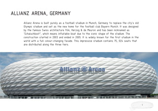
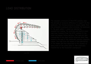
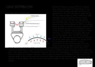
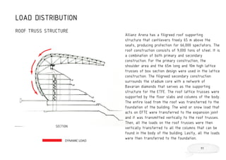
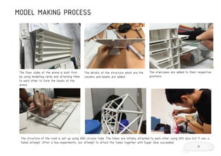
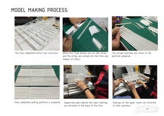
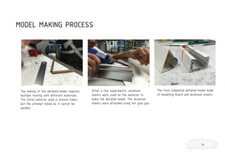
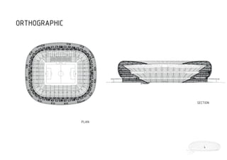
The document provides details about the Allianz Arena stadium in Munich, Germany. It summarizes the key aspects of the stadium's design including its unique ETFE cushion facade that can change colors to represent the home team. The structural system uses a steel lattice roof structure supported by concrete columns to distribute loads from the air-inflated ETFE surface structure to the foundation. The document also describes the model making process used to demonstrate the structural concepts.
1. [ARC 2513] BUILDING CONSTRUCTION 2
PROJECT 2: UNDERSTANDING FORCES IN SOLID
STRUCTURE &SURFACE STRUCTURE
CHUNG WEI JIN 0313789
LEE CHAER SHEAN 0313675
LIM YEE QUN 0319121
LOW YONG GING 0313679
ONG HUEY FEN 0314263
PEH KER NENG 0314619
TUTOR: PN NORITA
2. TABLE OF CONTENT:
Introduction
Architect’s Biography
Design Concept
Orthographic Drawings
Construction Method
Structural System:
i. Skeletal Structure
ii. surface Structure
Load Distribution
Model Making
References
1
2
3
4
5
6
7
9
12
15
3. ALLIANZ ARENA, GERMANY
Allianz Arena is built purely as a football stadium in Munich, Germany to replace the city’s old
Olympic stadium and set as the new home for the football club Bayern Munich. It was designed
by the famous Swiss architecture film, Herzog & de Meuron and has been nicknamed as
‘Schaluchboot”, which means inflatable boat due to the iconic shape of the stadium. The
construction started in 2003 and ended in 2005. It is widely known for the first stadium in the
world with a full colour-changing facade. This impressive stadium contains 75, 024 seats that
are distributed along the three tiers.
1
4. Principles: Jacques Herzog and Pierre de Meuron
Based in Basel, Switzerland
Founded in 1978
Style: Combines the artistry of European tradition
with the fresh approach of a new century’s technical
capabilities in extraordinarily inventive architectural
solutions to their clients’ needs.
Award:
Pritzker Aechitecture Prize 2001
HERZOG & DE MEURON ARCHITEKTEN
2
5. Allianz Arena in Munich sets a new architectural milestone in stadium design. The architecture of
Allianz Arena was modified from the Olympic Stadium in Munich, which is one of the most well
known post-war architecture in Germany. The white oval building symbolizes an abstract sculpture
in the landscape. The most striking part of the arena is the unique diamond-shape pattern facade
that resembles blown glass at far which is actually covered by plastic cushions that can be seen
through. The facade is made of ethylene tetrafluoroehylene (ETFE) foil, which can be illiminated in
the colours of whichever home team is playing. It is the first football stadium in the world coming
out with this exciting and effective idea that made the stadium became identifiable. The enclosure
design was evolved from a basket-like arrangement of woven ribbon elements. All these elements
reflect in similar fashion to the Bavarian flag.
DESIGN CONCEPT
3
6. MASTIC ASPHALT
CONCRETE FILIGREE BEAM FLOOR
REINFORCED-CONCRETE FLOOR BEAM
REINFORCED-CONCRETE COMPOSITE COLUMN
PRECAST SPUN CONCRETE COLUMN
LIGHTING UNIT
FACADE BRACKET
ETFE SHEETING
POST-AND-RAIL
FACADE WITH DOUBLE GLAZING
FIBRE-CEMENT SHEETING
WITH SMOOTH RENDER FINISH
SECONDARY CONSTRUCTION
The covering area of the building is split up in the
roof consisting of two-layered white and transparent
foil cushions as well as the facade with foil cushions
whose outside is printed. This printed foil cushions
are needed as the stadium will be illuminated by the
individual club colours during soccer matches. This can
be achieve by installing spotlights at the inner side
of the facades. The stadium offers rain-protected
seats for approximately 67, 000 spectators. For this
purpose, Europe’s biggest underground car park is
built with approximately 11, 000 parking spaces. Light
transmission into the arena is of 95% which is helped
by the transparent building covering made of air-
supported, two-layered ETFE foil suchions. There are
2816 individual rhomboid cushions which are connected
to a permanent sealing of the sealing joints of these
cushions. The sub structure consists of concrete in
which 96 radial, 50 m cantilevering steel framework
trusses stiffened by ring purlins and trusses are
planned beneath the roofing. On this structure, the
steel transoms are fixed to whcih the rhomboid
cushions will be water tight connected.
CONSTRUCTION METHOD
5
7. STEEL LATTICE STRUCTURE
The roof of the arena consists of 50 m cantilevering steel framework trusses that are made in lattice manner
which was supported by the pillars. Structural frames, which are made up of latticed units that have standardized
rods as web members, are used for large span bays. The loads will be transmitted from the roof to the cross
beams that are located beneath the framework. It will then transfer to the base.
STRUCTURAL SYSTEM: SKELETAL STRUCTURE
ADVANTAGES:
Great strength, high quality, lightweight,uniformity, durable, high ductility and elasticity.
DISADVANTAGES:
High maintenance cost, irresistant to corrosion, thermal transmission
6
8. Air inflated structure is a type of structure that is permanently inflated by air pressure. The structure covers
facilities that are not used for human occupancy such as water storage facilities and sewage treatment plants.
The inflation of air has to be amended to withstand the main loads, which are the internal air pressure, wind
force, and the load of snow build-up. High quality structures will increase the endurable forces, weight and wind
force. To push the structure up from the ground, the air pressure on the envelope must be equivalent to the air
pressure exerted on the inside ground. Therefore, the structure must be anchored to the ground securely by
using a high weight ground anchor.
STRUCTURAL SYSTEM: SURFACE STRUCTURE
AIR INFLATED STRUCTURE
SNOW LOAD
TENSION
FORCE
WIND
LOAD
INTERNAL PRESSURE TENSION
FORCE
7
9. The membrane structure is made of Ethylene
Tetrafluoro Ethylene (ETFE) foil, which is a fluorine
based plastic. ETFE are highly tear resistance and
lightweight with high translucency. Due to its ability
on preventing deterioration from moisture and
ultraviolet radiation, it has a long life span. ETFE has
been used as a replacement for glazing because of its
high light transmission properties.
ADVANTAGES:
Light weight, the possibility of covering large spans
without internal supports, completely prefabricated,
rapid assembly, portability, transparency to light and
radio waves, and low cost.
DISADVANTAGES:
Regular maintenance of excess pressure in the
Senvelope, the relatively short service life, and poor
fire resistance and acoustic insulation.
MATERIAL USED
8
10. The pneumatic structure of the ETFE cushions uses
the principle of pressure difference to support its thin
membrane. The internal pressure is always higher than
the atmospheric pressure which stresses the membrane
to the point where it cannot be indented by
asymmetrical loading. The external wind load or snow
load then transmits from the ETFE cushions to the
steel rectangular hollow sections. The load are then
transmitted to the steel lattice structure which then
conducts the load to the reinforced concrete composite
column. The load from the column is then distributed
to the beams and then dispersed to the columns on
every level of the arena which is then eventually
transferred to the foundation underground.
SECTION
LOAD DISTRIBUTION
DYNAMIC LOAD STATIC LOAD
9
11. Ethylene Tetrafluoro Ethylene (ETFE) foil cushions
were used as the façade for Allianz Arena. It was
divided up into lozenge shape and was made up of
polycarbonate. The ETFE were light in weight due to
the thin membrane which is 0.2mm. Furthermore, ETFE
have high insulating properties and are visually
attractive. The thin membrane was supported by
pressure differences. The pre-stressing of the foil
caused by the internal pressure of 300 Pa in cushions
serves primarily to stabilize the cushions against wind.
It was designed in a way to prevent excessive wind
forces acting on the foil, reducing deformation. Other
than that, it was designed to cut down water load
acts on the cushions. Also, the ETFE were joined
together with the expansion joint which was known as
the second construction innovation. It was due solely
to the innovation that areas for the steel
substructure for the cushion envelope and in the
Allianz Arena could be made continuously. Without
that, the opening and closing of the expansion joint could possibly destroy the thin foil cushions due to the
variation of temperature in long term. Moreover, that innovation consists of spring steel plate at each expansion
joint in the obtuse corners of the diamond. To prevent the thin foil from damaging, it translates the change in the
width of the joint into a change in the span of the cushions. In conclusion, the thickness of foils results in the
unloaded weight of the covering and substructure are directed together with external loads from wind or snow
pressure to the foundation, the cross-sections and unloaded weights of the entire load-bearing construction are
reduced.
LOAD DISTRIBUTION
AIR INFLATED STRUCTURE
SNOW LOAD
TENSION
FORCE
WIND
LOAD
INTERNAL PRESSURE TENSION
FORCE
TENSION FORCE
10
12. Allianz Arena has a filigreed roof supporting
structure that cantilevers freely 65 m above the
seats, producing protection for 66,000 spectators. The
roof construction consists of 9,000 tons of steel. It is
a combination of both primary and secondary
construction. For the primary construction, the
shoulder area and the 65m long and 10m high lattice
trusses of box section design were used in the lattice
construction. The filigreed secondary construction
surrounds the stadium core with a network of
Bavarian diamonds that serves as the supporting
structure for the ETFE. The roof lattice trusses were
supported by the floor slabs and columns of the body.
The entire load from the roof was transferred to the
foundation of the building. The wind or snow load that
acts on EFTE were transferred to the expansion joint
and it was transmitted vertically to the roof trusses.
Then, all the loads on the roof trusses were then
vertically transferred to all the columns that can be
found in the body of the building. Lastly, all the loads
were then transferred to the foundation.
LOAD DISTRIBUTION
ROOF TRUSS STRUCTURE
DYNAMIC LOAD
SECTION
11
13. MODEL MAKING PROCESS
The floor slabs of the arena is built first
by using modelling cards and attaching them
to each other to form the levels of the
arena.
The details of the structure which are the
columns and beams are added.
The staircases are added to their respective
positions.
The structure of the rood is set up using ABS circular tube. The tubes are initially attached to each other using UHU glue but it was a
failed attempt. After a few experiments, our attempt to attach the tubes together with Super Glue succeeded.
12
14. MODEL MAKING PROCESS
The final completed lattice roof structure. White PVC foam boards are cut into strips
and the strips are carved into the form and
shapes of chairs.
The carved staircase are stuck to the
platform prepared.
Final completed seating platform is prepared. Supporting walls behind the lower seatings
are attached to the base of the floor.
Seatings on the upper levels are attached
to their positions.
13
15. The making of the detailed model requires
multiple testing with different materials.
The initial material used is bronze tubes
but the attempt failed as it cannot be
welded.
After a few experiments, aluminum
sheets were used as the material to
make the detailed model. The aluminum
sheets were attached using hot glue gun.
The final completed detailed model made
of modelling board and aluminum sheets.
MODEL MAKING PROCESS
14
16. REFERENCES
1. Metz, T. (n.d.). Herzog & de Meuron’s cushiony chameleon glows with rival teams’ colors. Retrieved June 22,
2015, from http://www.csus.edu/indiv/s/shawg/articles/arena/stadia.pdf
2. I, L. (2012, June 22). Allianz Arena - Bayern Munich Football Stadium - e-architect. Retrieved June 22, 2015,
from http://www.e-architect.co.uk/munich/allianz-arena-munich
3. Angelo, S. (n.d.). World Stadiums - Stadium Design :: Allianz Arena in München. Retrieved June 19, 2015, from
http://www.worldstadiums.com/stadium_menu/architecture/stadium_design/munchen_allianz.shtml
4. Football Mutant Bubble. (2005, July 19). Retrieved June 22, 2015, from http://www.domusweb.it/en/architec-
ture/2005/07/19/football-mutant-bubble.html
5. Nuts and bolts. (n.d.). Retrieved June 16, 2015, from https://www.allianz-arena.de/en/fakten/detaillierte-zahlen/
6. Argawal, A. (n.d.). Pneumatic structure technology. Retrieved June 18, 2015, from http://www.academ-
ia.edu/2393736/pneumatic_structure_technology
7. Wood, D. (2012, September 1). Marlins' Retractable Roof Braces Itself for Storms. Retrieved June 14, 2015, from
http://southeast.construction.com/southeast_construction_projects/2012/0109-miami-marlins-ballpark8217s.asp
15