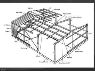
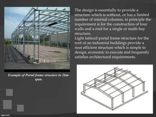
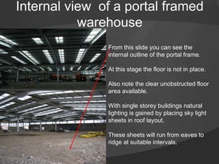
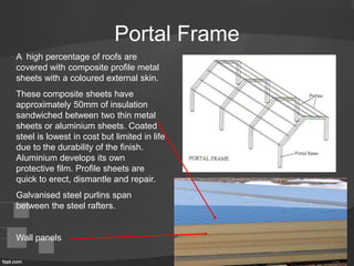
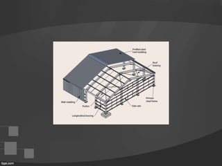
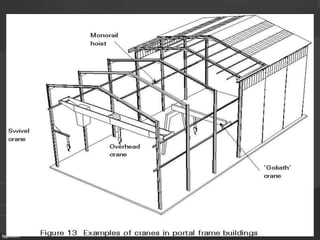
PORTAL FRAME
STRUCTURE
Portal frames are made in a variety of shapes and sizes.
They are usually made from steel, but can also be made
from concrete or timber. The portal structure is designed in
such a way that it has no intermediate columns, as a result
large open areas can easily be created within the structure.
Portal Frames are generally used for single storey
construction which require a large unobstructed floor space
ie
–Factories
–Shopping Centres
–Warehouses
INTRODUCTION
Portal Framed Construction
Large unobstructed floor space
PORTAL FRAME definition
• Portal frames are single storey, single( or multi-bay) frames with pitched or
flat roof. Fabricated from universal beams, it is an ideal structural solution
in many circumstances, regarding its economic and structural efficiency.
The system is specially ideal for industrial buildings due to its ability to
span large areas of unobstructed open space within its building envelope.
This is made possible through the design and use of prefabricated steel
sections. Technological advance in the footing system also cooperate for the
large span achieved due to their ability to carry greater loads (or its
efficiency to transfer and distribute the loads to the foundation).
• Three major elements are; cladding for both roof and walls; secondary steel
to support the cladding and form framing for doors, windows and the like;
and the main framework of the structure, including all necessary bracing.
In addition, the building requires appropriate footings designed to transmit
all the load to the foundations( supporting soil).
The design is essentially to provide a
structure which is without, or has a limited
number of internal columns, in principle the
requirement is for the construction of four
walls and a roof for a single or multi-bay
structure.
Light latticed portal frame structure for the
roof of an industrial buildings provide a
neat efficient structure which is simple to
design, economic to execute and frequently
satisfies architectural requirements.
Example of Portal frame structure in 26m-
span.
Internal view of a portal framed
warehouse
From this slide you can see the
internal outline of the portal frame.
At this stage the floor is not in place.
Also note the clear unobstructed floor
area available.
With single storey buildings natural
lighting is gained by placing sky light
sheets in roof layout.
These sheets will run from eaves to
ridge at suitable intervals.
Portal Frame
A high percentage of roofs are
covered with composite profile metal
sheets with a coloured external skin.
These composite sheets have
approximately 50mm of insulation
sandwiched between two thin metal
sheets or aluminium sheets. Coated
steel is lowest in cost but limited in life
due to the durability of the finish.
Aluminium develops its own
protective film. Profile sheets are
quick to erect, dismantle and repair.
Galvanised steel purlins span
between the steel rafters.
Wall panels
FOOTINGS
Due to the point loads
applied to the foundation,
Pad footings are
respectably the most
suitable in long-span portal
frame construction. Also in
achieving a workable
surface and the distribution
of loads to the foundation,
combined concrete slab
would be used along with
the Pad footing. The
reinforcements and metal
dowels also play a big part
in the sufficient footings
behaviour.
There are 3 types of connection systems for a Portal Frame structure.
• Rigid base
• 2 pin
• 3 pin
The 3 types mentioned above are of purely how rigid or flexible the connections are at the
apex, knee, and the base. This however relates greatly to the load transfer of the structure,
as the bending moment becomes a big issue. Rigid bases are used much commonly in the
current construction due to its ability to carry the bending moment and axial loads, thus
giving the framework a much lighter finish. (Max bending moment at the knee, apex and
base)
Pinned bases however transmit the bending moment straight through to the foundation.
(max bending moment at the apex and knees for the 2 pin, max bending moment at the
knee for the 3 pin.)
PINNED BASE TO PORTAL
FIXED BASE CONNECTION
The advantage of using steel as the material is due to the ability to design
relatively light, long-span, durable, and is easy to erect safely and quickly.
A primary requirement is flexibility of planning which results in a
demand for as few columns as possible. The ability to provide spans up
to 60m (most commonly around 30m), using steel has proved very
popular for commercial and leisure buildings. The lightness and
flexibility of this kind of steel structure reduces the sizes and the costs of
foundations and make them less sensitive to the geotechnical
characteristics of the soil.
The structural envelope are simple, it is essential to ascertain correctly the
load applied to the structure and to predict the load paths from the load
applied through to the foundations.
(e.g. Sheeting to the purlins and side rails, through the roof girder to the
column and finally to the foundation and supporting soil.
Diagram- shows the difference in the base, rigid and
pin.
THE BENDING MOMENTS-
PURLINS and RAFTERS; Purlins and Rafters are the essential beams that make up the portal
frame structure. Purlins are the beams that run the length of the frame connected to the rafters,
the purlins are bolt connected by the cleat that is welded to the rafter. The purlins are directed
towards the apex with a pitch to achieve the best possible performance. The size of the sections
of these beams is specified by the engineer, along with the size of the web and flange,
depending on the spans and load derived from the design.
EAVES connection;
The eaves connections are in many different forms and changed forms through
history of construction. Originally the diagonal connection plane was considered,
however there was a major stability problem at the inside corner.
•Tapered portal frames fabricated by automatic welding can be utilised to
create aesthetic and economical industrial buildings.
•The behaviour of fabricated sections with slender webs is more complex than
that of rolled sections; the resistance checks must take account of local
buckling, cross-section distortion and the interaction between the primary and
secondary structure through the stays.
Spatial requirements of the client:
The selected system provide the client with adequate space to utilise the floor space
according to their business needs. As buildings will often change hands throughout their
working life, a re-fit of the warehouse and/or office space may be necessary. Structural
members with significant spanning capacity allow the occupant to carry-out such activities
without the expense of making structural alterations.
Appropriateness of steel portals in this issue.
Steel has extremely high material strength in both compression and tension. With a
Young’s Modulus of 200,000Mpa, it is by far the stiffest of all conventional building
materials. These two characteristics of steel are most exemplified in the design of universal
beams and columns. Universal beams have excellent spanning capacity, making their
application in portal frame construction the most desired framing option for medium-sized
industrial construction.
Appropriateness of saw-tooth construction in addressing issue.
Saw-tooth trusses were used in close span construction, which was prevalent prior to the
mid 1970’s. Unlike portal frames, buildings with saw-tooth trusses had to be designed in a
series of bays, supported by load-bearing columns. Such design is far more restrictive than
portal framing in allowing spatial freedom to the end user.
Adaptability of the structural system to a variety of site conditions.
Structural systems that can be constructed in extreme conditions are likely to be popular
with building designers. On sites with high, extreme or abnormal moisture conditions,
differential movement may cause excess structural deflection. This can adversely affect the
aesthetic quality of the building, leading to costly repair work.
Base joint for Portal Frame
The legs or stanchions of the portal frame
need connecting at the bottom to a
foundation.
Here we can see the base joint connection
in place.
Ridge joint for Portal Frame
Shown here is a ridge joint or apex
joint.
It is Important that this joint is
strong hence the use of wedge
shaped pieces called gusset pieces
to strengthen and increase the bolt
area.
Knee joint for Portal Frame
• Again the knee joint must be
strong to support the roof loads
and prevent bending.
• Gusset pieces will be used to
increase strength, give greater
bolt area and prevent deflection
under load.
Diagonal bracing for Portal Frame
With all types of frameworks we must think on stability ie
movement. To help strengthen the framework and prevent
movement diagonal bracing will be used.
Cladding rails for Portal Frame
• This slide shows the
cladding rails for
attaching the external
metal cladding panels
to.
• These rails can be
fixed horizontal or
vertical depending on
the way the cladding
panels are fixed.
Tie cables for Portal Frame
• These wire and tubular
ties are used to
prevent sagging of the
cladding rails which
can add considerable
force unto the joints of
the external cladding.
External wall detail
• Here we see the finish
of the external
cladding panels with
the lower level facing
brickwork.
• The blockwork behind
creates a protective
wall or firewall.
Advantages and disadvantages
of steel Portal Frames
Advantages
• Speed and ease of erection
• Building can be quickly closed in and made water tight.
• Framework prefabricated in a workshop and not affected by weather.
• Site works such as drainage, roads etc can be carried out until
framework is ready for erection.
• No weather hold up during erecting the framework.
• Connected together in factories by welding and site connections should
be bolted.
Disadvantages
• Although steel is incombustible it has a poor resistance to fire as it
bends easily when hot.
• Subject to corrosion
LONG SPAN TIMBER STRUCTURES:
Long-span structures( span 30m or
greater) can also be constructed using
timber (mainly plywood) as the material.
Long-span structures require a level of
technical sophistication that indicates a
confidence in timber as a structural and
aesthetic medium on the part of the
designers.
The spanning potential of timber portal
frame structure can reach around 50
metres, and provides an extremely
economic solution.
diagram- a typical plywood gusset (solid section).. diagram – Timber portal frame structure
By collaborating steel knee joints with glue-laminated Timber products, Timber portal
frame structures to form large-span structure can be produced. The economical aspect
of this material can not be surpassed.
The Plywood Gusset
The Steel Plate and Dowel Knee Joint Bracket; although this is not a timber product, it is
used in conjunction with timber columns and rafters to provide a steady connection
system.
The various timber products used in those of Timber Portal Frame structures are;
TIMBER PORTAL FRAME
construction process:
DURING CRANE LIFTING THE STRUCTURE;
the rafters, purlins and roof bracing are
fabricated on the site, the roof is then lifted on
and joined to the columns (this process can be
done as a whole, or by sections). Elements such
as the gussets and purlins are then installed.
All purlins should have all connections
installed, including joist brackets, tension
straps and fly braces. The rest of the major
connection joints such as the knee gussets must
also be fixed along with required bracings.
Temporary bracing is also fitted, due to the
support the structure needs when the support
from the crane is released.
AFTER CRANE DETACHED;
After the cranes are detached, the remainder of
the fixing/nailing takes place, this is when the
detailed installations are carried out, such as;
girts, eaves, mullions, remaining purlins and
additional roof wind bracings.
Though Timber being a highly economic
solution in structural frames, it is also highly
flammable and prone to elemental attacks, and
due to the natural property of the material, it
needs to be tested before any type of work is
done to check the performance of the timber.
The tests include trial fabrication and
treatments (paints and chemical protection
coating must be applied before the erection).

08 - Portal Frame.pptx

  • 1.
  • 2.
    Portal frames aremade in a variety of shapes and sizes. They are usually made from steel, but can also be made from concrete or timber. The portal structure is designed in such a way that it has no intermediate columns, as a result large open areas can easily be created within the structure. Portal Frames are generally used for single storey construction which require a large unobstructed floor space ie –Factories –Shopping Centres –Warehouses INTRODUCTION
  • 3.
    Portal Framed Construction Largeunobstructed floor space
  • 4.
    PORTAL FRAME definition •Portal frames are single storey, single( or multi-bay) frames with pitched or flat roof. Fabricated from universal beams, it is an ideal structural solution in many circumstances, regarding its economic and structural efficiency. The system is specially ideal for industrial buildings due to its ability to span large areas of unobstructed open space within its building envelope. This is made possible through the design and use of prefabricated steel sections. Technological advance in the footing system also cooperate for the large span achieved due to their ability to carry greater loads (or its efficiency to transfer and distribute the loads to the foundation). • Three major elements are; cladding for both roof and walls; secondary steel to support the cladding and form framing for doors, windows and the like; and the main framework of the structure, including all necessary bracing. In addition, the building requires appropriate footings designed to transmit all the load to the foundations( supporting soil).
  • 6.
    The design isessentially to provide a structure which is without, or has a limited number of internal columns, in principle the requirement is for the construction of four walls and a roof for a single or multi-bay structure. Light latticed portal frame structure for the roof of an industrial buildings provide a neat efficient structure which is simple to design, economic to execute and frequently satisfies architectural requirements. Example of Portal frame structure in 26m- span.
  • 7.
    Internal view ofa portal framed warehouse From this slide you can see the internal outline of the portal frame. At this stage the floor is not in place. Also note the clear unobstructed floor area available. With single storey buildings natural lighting is gained by placing sky light sheets in roof layout. These sheets will run from eaves to ridge at suitable intervals.
  • 8.
    Portal Frame A highpercentage of roofs are covered with composite profile metal sheets with a coloured external skin. These composite sheets have approximately 50mm of insulation sandwiched between two thin metal sheets or aluminium sheets. Coated steel is lowest in cost but limited in life due to the durability of the finish. Aluminium develops its own protective film. Profile sheets are quick to erect, dismantle and repair. Galvanised steel purlins span between the steel rafters. Wall panels
  • 12.
    FOOTINGS Due to thepoint loads applied to the foundation, Pad footings are respectably the most suitable in long-span portal frame construction. Also in achieving a workable surface and the distribution of loads to the foundation, combined concrete slab would be used along with the Pad footing. The reinforcements and metal dowels also play a big part in the sufficient footings behaviour.
  • 13.
    There are 3types of connection systems for a Portal Frame structure. • Rigid base • 2 pin • 3 pin The 3 types mentioned above are of purely how rigid or flexible the connections are at the apex, knee, and the base. This however relates greatly to the load transfer of the structure, as the bending moment becomes a big issue. Rigid bases are used much commonly in the current construction due to its ability to carry the bending moment and axial loads, thus giving the framework a much lighter finish. (Max bending moment at the knee, apex and base) Pinned bases however transmit the bending moment straight through to the foundation. (max bending moment at the apex and knees for the 2 pin, max bending moment at the knee for the 3 pin.) PINNED BASE TO PORTAL FIXED BASE CONNECTION
  • 15.
    The advantage ofusing steel as the material is due to the ability to design relatively light, long-span, durable, and is easy to erect safely and quickly. A primary requirement is flexibility of planning which results in a demand for as few columns as possible. The ability to provide spans up to 60m (most commonly around 30m), using steel has proved very popular for commercial and leisure buildings. The lightness and flexibility of this kind of steel structure reduces the sizes and the costs of foundations and make them less sensitive to the geotechnical characteristics of the soil. The structural envelope are simple, it is essential to ascertain correctly the load applied to the structure and to predict the load paths from the load applied through to the foundations. (e.g. Sheeting to the purlins and side rails, through the roof girder to the column and finally to the foundation and supporting soil.
  • 16.
    Diagram- shows thedifference in the base, rigid and pin.
  • 17.
    THE BENDING MOMENTS- PURLINSand RAFTERS; Purlins and Rafters are the essential beams that make up the portal frame structure. Purlins are the beams that run the length of the frame connected to the rafters, the purlins are bolt connected by the cleat that is welded to the rafter. The purlins are directed towards the apex with a pitch to achieve the best possible performance. The size of the sections of these beams is specified by the engineer, along with the size of the web and flange, depending on the spans and load derived from the design. EAVES connection; The eaves connections are in many different forms and changed forms through history of construction. Originally the diagonal connection plane was considered, however there was a major stability problem at the inside corner. •Tapered portal frames fabricated by automatic welding can be utilised to create aesthetic and economical industrial buildings. •The behaviour of fabricated sections with slender webs is more complex than that of rolled sections; the resistance checks must take account of local buckling, cross-section distortion and the interaction between the primary and secondary structure through the stays.
  • 18.
    Spatial requirements ofthe client: The selected system provide the client with adequate space to utilise the floor space according to their business needs. As buildings will often change hands throughout their working life, a re-fit of the warehouse and/or office space may be necessary. Structural members with significant spanning capacity allow the occupant to carry-out such activities without the expense of making structural alterations. Appropriateness of steel portals in this issue. Steel has extremely high material strength in both compression and tension. With a Young’s Modulus of 200,000Mpa, it is by far the stiffest of all conventional building materials. These two characteristics of steel are most exemplified in the design of universal beams and columns. Universal beams have excellent spanning capacity, making their application in portal frame construction the most desired framing option for medium-sized industrial construction. Appropriateness of saw-tooth construction in addressing issue. Saw-tooth trusses were used in close span construction, which was prevalent prior to the mid 1970’s. Unlike portal frames, buildings with saw-tooth trusses had to be designed in a series of bays, supported by load-bearing columns. Such design is far more restrictive than portal framing in allowing spatial freedom to the end user. Adaptability of the structural system to a variety of site conditions. Structural systems that can be constructed in extreme conditions are likely to be popular with building designers. On sites with high, extreme or abnormal moisture conditions, differential movement may cause excess structural deflection. This can adversely affect the aesthetic quality of the building, leading to costly repair work.
  • 19.
    Base joint forPortal Frame The legs or stanchions of the portal frame need connecting at the bottom to a foundation. Here we can see the base joint connection in place.
  • 20.
    Ridge joint forPortal Frame Shown here is a ridge joint or apex joint. It is Important that this joint is strong hence the use of wedge shaped pieces called gusset pieces to strengthen and increase the bolt area.
  • 21.
    Knee joint forPortal Frame • Again the knee joint must be strong to support the roof loads and prevent bending. • Gusset pieces will be used to increase strength, give greater bolt area and prevent deflection under load.
  • 22.
    Diagonal bracing forPortal Frame With all types of frameworks we must think on stability ie movement. To help strengthen the framework and prevent movement diagonal bracing will be used.
  • 23.
    Cladding rails forPortal Frame • This slide shows the cladding rails for attaching the external metal cladding panels to. • These rails can be fixed horizontal or vertical depending on the way the cladding panels are fixed.
  • 24.
    Tie cables forPortal Frame • These wire and tubular ties are used to prevent sagging of the cladding rails which can add considerable force unto the joints of the external cladding.
  • 25.
    External wall detail •Here we see the finish of the external cladding panels with the lower level facing brickwork. • The blockwork behind creates a protective wall or firewall.
  • 33.
    Advantages and disadvantages ofsteel Portal Frames Advantages • Speed and ease of erection • Building can be quickly closed in and made water tight. • Framework prefabricated in a workshop and not affected by weather. • Site works such as drainage, roads etc can be carried out until framework is ready for erection. • No weather hold up during erecting the framework. • Connected together in factories by welding and site connections should be bolted. Disadvantages • Although steel is incombustible it has a poor resistance to fire as it bends easily when hot. • Subject to corrosion
  • 34.
    LONG SPAN TIMBERSTRUCTURES: Long-span structures( span 30m or greater) can also be constructed using timber (mainly plywood) as the material. Long-span structures require a level of technical sophistication that indicates a confidence in timber as a structural and aesthetic medium on the part of the designers. The spanning potential of timber portal frame structure can reach around 50 metres, and provides an extremely economic solution.
  • 35.
    diagram- a typicalplywood gusset (solid section).. diagram – Timber portal frame structure By collaborating steel knee joints with glue-laminated Timber products, Timber portal frame structures to form large-span structure can be produced. The economical aspect of this material can not be surpassed. The Plywood Gusset The Steel Plate and Dowel Knee Joint Bracket; although this is not a timber product, it is used in conjunction with timber columns and rafters to provide a steady connection system. The various timber products used in those of Timber Portal Frame structures are;
  • 36.
    TIMBER PORTAL FRAME constructionprocess: DURING CRANE LIFTING THE STRUCTURE; the rafters, purlins and roof bracing are fabricated on the site, the roof is then lifted on and joined to the columns (this process can be done as a whole, or by sections). Elements such as the gussets and purlins are then installed. All purlins should have all connections installed, including joist brackets, tension straps and fly braces. The rest of the major connection joints such as the knee gussets must also be fixed along with required bracings. Temporary bracing is also fitted, due to the support the structure needs when the support from the crane is released. AFTER CRANE DETACHED; After the cranes are detached, the remainder of the fixing/nailing takes place, this is when the detailed installations are carried out, such as; girts, eaves, mullions, remaining purlins and additional roof wind bracings. Though Timber being a highly economic solution in structural frames, it is also highly flammable and prone to elemental attacks, and due to the natural property of the material, it needs to be tested before any type of work is done to check the performance of the timber. The tests include trial fabrication and treatments (paints and chemical protection coating must be applied before the erection).