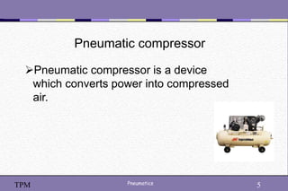
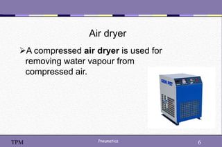
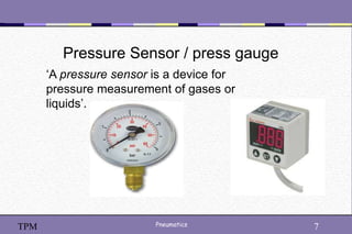
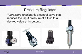
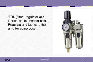
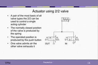
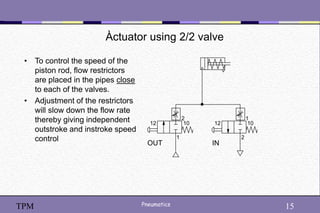
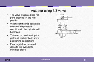
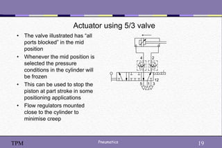
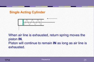
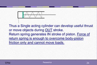
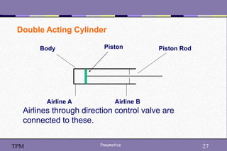
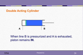
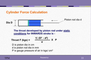
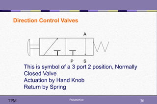
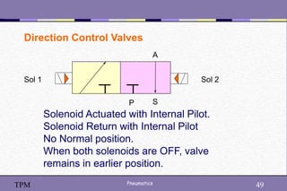
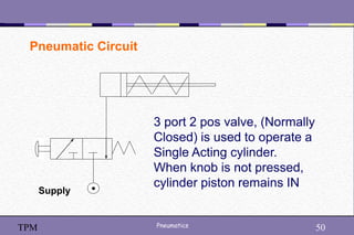
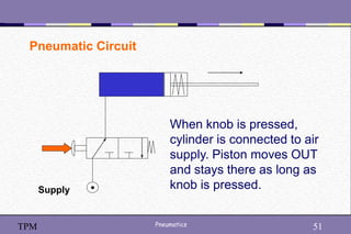
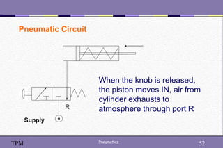
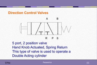
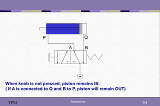
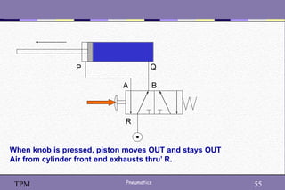
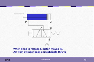
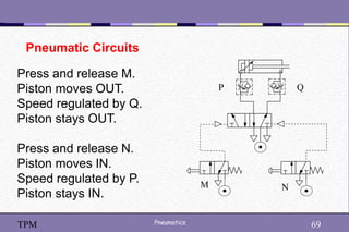
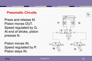
1
Pneumatics 1
TPM
2
Pneumatics 2
TPM
Introduction of pneumatic
3
Pneumatics 3
TPM
Introduction of pneumatic
4
Pneumatics 4
TPM
Main component of pneumatic
Pneumatic compressor
Dryer
Pressure sensor / press gauge
Pressure Regulator
Pneumatic reservoir
Solenoid valve
Pneumatic actuator
5
Pneumatics 5
TPM
Pneumatic compressor
Pneumatic compressor is a device
which converts power into compressed
air.
6
Pneumatics 6
TPM
Air dryer
A compressed air dryer is used for
removing water vapour from
compressed air.
7
Pneumatics 7
TPM
Pressure Sensor / press gauge
‘A pressure sensor is a device for
pressure measurement of gases or
liquids’.
8
Pneumatics 8
TPM
Pressure Regulator
‘A pressure regulator is a control valve that
reduces the input pressure of a fluid to a
desired value at its output’.
9
Pneumatics 9
TPM
‘FRL (filter , regulator and
lubricator). Is used for filter,
Regulate and lubricate the
air after compressor’.
10
Pneumatics 10
TPM
Solenoid valves’.
• 2/2 Valve push button /
spring.
• 3/2 Valve push button /
spring
• 3/2 Valve detente lever
operated
2
1
3
12 10
2
10
12
1
1
2
3
12
10
11
Pneumatics 11
TPM
Solenoid valves’.
• 3/2 Valve differential
pressure operated
• 5/2 Valve push button /
spring
• 5/3 Valve double pressure
operated spring centre
1
2
4
5 3
14 12
1
2
4
5 3
1
2
3
12 10
12
Pneumatics 12
TPM
5/3 Solenoid valves’.
 Type 1. All ports blocked
 Type 2. Outlets to exhaust
 Type 3. Supply to outlets
13
Pneumatics 13
TPM
Symbols
• Non-return valve
• Flow regulator uni-directional
• Flow regulator bi-directional
• Two pressure ‘AND’
• Shuttle valve ‘OR’
• Silencer
• Quick exhaust valve with
silencer
• Pressure to electric switch
adjustable
14
Pneumatics 14
TPM
Àctuator using 2/2 valve
• A pair of the most basic of all
valve types the 2/2 can be
used to control a single
acting cylinder
• The normally closed position
of the valve is produced by
the spring
• The operated position is
produced by the push button
• One valve admits air the
other valve exhausts it
2
10
12
1
1
10
12
2
OUT IN
15
Pneumatics 15
TPM
Àctuator using 2/2 valve
• To control the speed of the
piston rod, flow restrictors
are placed in the pipes close
to each of the valves.
• Adjustment of the restrictors
will slow down the flow rate
thereby giving independent
outstroke and instroke speed
control
10
12 10
12
OUT IN
2
1
1
2
16
Pneumatics 16
TPM
Àctuator using 5/3 valve
• The valve illustrated has “all
ports blocked” in the mid
position
• Whenever the mid position is
selected the pressure
conditions in the cylinder will
be frozen
• This can be used to stop the
piston at part stroke in some
positioning applications
• Flow regulators mounted
close to the cylinder to
minimise creep
2
4
1
5 3
14 12
17
Pneumatics 17
TPM
Àctuator using 5/3 valve
• The valve illustrated has “all
ports blocked” in the mid
position
• Whenever the mid position is
selected the pressure
conditions in the cylinder will
be frozen
• This can be used to stop the
piston at part stroke in some
positioning applications
• Flow regulators mounted
close to the cylinder to
minimise creep
2
4
1
5 3
14 12
18
Pneumatics 18
TPM
Àctuator using 5/3 valve
• The valve illustrated has “all
ports blocked” in the mid
position
• Whenever the mid position is
selected the pressure
conditions in the cylinder will
be frozen
• This can be used to stop the
piston at part stroke in some
positioning applications
• Flow regulators mounted
close to the cylinder to
minimise creep
2
4
1
5 3
14 12
19
Pneumatics 19
TPM
Actuator using 5/3 valve
• The valve illustrated has “all
ports blocked” in the mid
position
• Whenever the mid position is
selected the pressure
conditions in the cylinder will
be frozen
• This can be used to stop the
piston at part stroke in some
positioning applications
• Flow regulators mounted
close to the cylinder to
minimise creep
2
4
1
5 3
12
20
Pneumatics 20
TPM
Actuator using 5/3 valve
• The valve illustrated has “all
ports blocked” in the mid
position
• Whenever the mid position is
selected the pressure
conditions in the cylinder will
be frozen
• This can be used to stop the
piston at part stroke in some
positioning applications
• Flow regulators mounted
close to the cylinder to
minimise creep
2
4
1
5 3
14 12
21
Pneumatics 21
TPM
 Air cylinder is an output device. It
consumes compressed air and gives
linear movement.
 It is used for moving objects, closing
machine guards, punching parts,
advancing slides, clamping parts etc.
Air Cylinders
22
Pneumatics 22
TPM
Air Cylinders are classified as Single Acting
and Double Acting
Air Cylinders
Single Acting Double Acting
23
Pneumatics 23
TPM
Single Acting Cylinder
Piston Rod
Body Return Spring
Airline thru’ direction control valve
connected here.
Exhaust port
24
Pneumatics 24
TPM
When air line is pressurized (that is connected to
compressed air), force developed by air pressure is
stronger than the spring and piston moves OUT,
compressing the spring. Piston remains OUT as long
as air line is pressurized.
Single Acting Cylinder
25
Pneumatics 25
TPM
When air line is exhausted, return spring moves the
piston IN.
Piston will continue to remain IN as long as air line is
exhausted.
Single Acting Cylinder
26
Pneumatics 26
TPM
Thus a Single acting cylinder can develop useful thrust
or move objects during OUT stroke.
Return spring generates IN stroke of piston. Force of
return spring is enough to overcome body-piston
friction only and cannot move loads.
27
Pneumatics 27
TPM
Double Acting Cylinder
Body Piston Rod
Airline A Airline B
Airlines through direction control valve are
connected to these.
Piston
28
Pneumatics 28
TPM
Double Acting Cylinder
A B
When line B is pressurized and A is exhausted,
piston remains IN.
29
Pneumatics 29
TPM
Double Acting Cylinder
A B
When line A is pressurized and B is exhausted,
piston moves OUT.
30
Pneumatics 30
TPM
Double Acting Cylinder animated.
Click on the picture to start and stop animation
31
Pneumatics 31
TPM
Cylinder Force Calculation
The thrust developed by piston rod under static
conditions for OUTWARDS stroke is -
Thrust F (kgs) =
D2
4
X P
Dia D
D is piston dia in cms
P is gauge pressure of air in kgs/ cm2
32
Pneumatics 32
TPM
Cylinder Force Calculation
Dia D
Example : Cylinder dia 40 mm,
Air Pressure – 5 bar gauge
Thrust = (3.14 x 16 x 5) / 4 = 62.8 kgs
Note thrust is under static conditions
33
Pneumatics 33
TPM
Cylinder Force Calculation
Dia D
Piston rod dia d
The thrust developed by piston rod under static
conditions for INWARDS stroke is -
Thrust F (kgs) =
(D2 - d2)
4
X P
D is piston dia in cm
d is piston rod dia in mm
P is gauge pressure of air in kgs/ cm2
34
Pneumatics 34
TPM
Cylinder – Mountings
35
Pneumatics 35
TPM
Direction Control Valves
We have seen that a single acting cylinder
needs air line alternately pressurized and
exhausted in order that the cylinder operates.
Direction Control Valves are Control Devices in
a Pneumatic circuit that pressurize and
exhaust air lines as desired.
36
Pneumatics 36
TPM
Direction Control Valves
P S
A
This is symbol of a 3 port 2 position, Normally
Closed Valve
Actuation by Hand Knob
Return by Spring
37
Pneumatics 37
TPM
Direction Control Valves
P S
A
3 ports are marked P, S and A
This means on the valve, we will find 3 threaded
ports.
38
Pneumatics 38
TPM
Direction Control Valves
P S
2 position means the valve can remain in 2 states. One
state when box 1 is operative. The other state is when
box 2 is operative.
A
Box 1
Box 2
39
Pneumatics 39
TPM
Direction Control Valves
P S
When Box 1 is operative, that is valve is in position 1,
ports are connected as below –
P is closed. A is connected to S.
A
Box 1
40
Pneumatics 40
TPM
Direction Control Valves
P S
When Box 2 is operative, that is valve is in position 2,
ports are connected as below –
P is connected to A. S is closed.
A
Box 2
41
Pneumatics 41
TPM
Direction Control Valves
P S
A
The ports are marked by letters as below –
P is Pressure port. Connected to supply.
A, B are System ports connected to devices
R,S,T are Exhaust ports connected to silencers.
42
Pneumatics 42
TPM
Direction Control Valves
P S
A
Actuation by Hand Knob, Return by Spring means –
When hand knob is pressed – Box 2 is operative
When hand knob is not pressed – Box 1 is operative because of the
Spring.
Box 1
Box 2
Spring
Hand
Knob
43
Pneumatics 43
TPM
Direction Control Valves
P S
A
Thus the valve has got a tendency to remain with Box 1 operative
whenever knob is not pressed. That is Normal position of valve.
Since port P is closed in that position, it is called Normally Closed
Valve.
Box 1
44
Pneumatics 44
TPM
Direction Control Valves
P S
A
Solenoid Actuated, Solenoid Return
No defined behavior if both solenoids are ON at the
same time. Care must be taken in designing electrical
circuit that this does not happen.
Sol 1 Sol 2
45
Pneumatics 45
TPM
Direction Control Valves
Solenoid is an electromagnet.
When energized it pulls a part
inside the valve ( a “spool” or a
“poppet”) to operate it.
46
Pneumatics 46
TPM
Such valve is called Solenoid Actuated with
Internal Pilot.
To restrict solenoid size and forces, in a solenoid
valve, a common design is to operate the spool
(or poppet) by using compressed air (available
from P port) as a pilot line and solenoid valve
pressurizes or exhausts the pilot line.
47
Pneumatics 47
TPM
Direction Control Valves
P S
A
Solenoid Actuated with Internal Pilot. Spring
Return.
Actually a valve as per above symbol is as
shown on next slide.
Sol 1
Note the arrow meaning internal pilot
48
Pneumatics 48
TPM
Direction Control Valves
P S
A
T
T
Pilot line
Pilot Exhaust
Actual construction of a Solenoid Actuated Internal
Pilot Valve. Spring Return
49
Pneumatics 49
TPM
Direction Control Valves
P S
A
Solenoid Actuated with Internal Pilot.
Solenoid Return with Internal Pilot
No Normal position.
When both solenoids are OFF, valve
remains in earlier position.
Sol 1 Sol 2
50
Pneumatics 50
TPM
Pneumatic Circuit
3 port 2 pos valve, (Normally
Closed) is used to operate a
Single Acting cylinder.
When knob is not pressed,
cylinder piston remains IN
Supply
51
Pneumatics 51
TPM
Pneumatic Circuit
When knob is pressed,
cylinder is connected to air
supply. Piston moves OUT
and stays there as long as
knob is pressed.
Supply
52
Pneumatics 52
TPM
Pneumatic Circuit
When the knob is released,
the piston moves IN, air from
cylinder exhausts to
atmosphere through port R
Supply
R
53
Pneumatics 53
TPM
P
R S
A B
5 port, 2 position valve
Hand Knob Actuated, Spring Return
This type of valve is used to operate a
Double Acting cylinder
Direction Control Valves
54
Pneumatics 54
TPM
When knob is not pressed, piston remains IN.
( If A is connected to Q and B to P, piston will remain OUT)
A B
P Q
55
Pneumatics 55
TPM
When knob is pressed, piston moves OUT and stays OUT
Air from cylinder front end exhausts thru’ R.
A B
P Q
R
56
Pneumatics 56
TPM
When knob is released, piston moves IN.
Air from cylinder back end exhausts thru’ S
A B
P Q
S
57
Pneumatics 57
TPM
 Ports are usually BSP internal threads like 1/8”,
1/4”, 3/8”, 1/2” etc
 For similarly designed valves the amount of air
flow through the valve usually increases with the
port size.
 Port size alone however cannot be relied upon to
give a standard value of flow as this is dependent
on the design of the orifice size.
Direction Control Valves – Port Size
58
Pneumatics 58
TPM
R3/8
R1/2
R1 R3/4
R1/4
R1/8
BSP Thread Sizes
Direction Control Valves – Port Size
59
Pneumatics 59
TPM
Direction Control Valves – Materials
Manufacturers offer valves in various materials.
For selection, general guidelines are –
Clean, dry conditions – Aluminum
Moist conditions – Brass
Hazardous conditions – Stainless Steel
60
Pneumatics 60
TPM
Direction Control Valves – Construction
DC valves - Spool and Poppet Type
DC Valves
Spool Type Poppet Type
61
Pneumatics 61
TPM
P S
A
X Y
P is connected to
A
S is closed
X is exhausted Y is pressurized
Working of a Spool Valve
62
Pneumatics 62
TPM
Specification of a DC Valve
 No of ports
 No of Positions
 Actuating Mechanism –pilot, solenoid, lever etc
 Return Mechanism – pilot, solenoid, spring etc
 Normally Open or Closed – if applicable
 Port Size – ¼”, ½” etc
 Operating Pressure
 Body Material – Brass, Stainless Steel etc
 Solenoid Voltage and Current – 24V DC
 Any Other – flameproof coil, manual override etc
 Supplier’s catalogue number
63
Pneumatics 63
TPM
Flow Control Valves (Throttle Valves)
Flow Control Valves are used to control speed of
Cylinders during movement.
Free Flow
Regulated Flow
Flow Control Valves allow Free flow in one direction and give
Regulated Flow (which is adjustable) in the other direction.
64
Pneumatics 64
TPM
Flow Control Valves
Free Flow
65
Pneumatics 65
TPM
Regulated Flow
Knob for adjustment
Flow Control Valves
66
Pneumatics 66
TPM
Flow Control Valves
Valve Q regulates OUT movement
of the piston.
Valve P regulates IN movement of
the piston.
P Q
67
Pneumatics 67
TPM
Pneumatic Circuits
P Q
Press valve P.
Piston will move OUT.
Release P. Press Q.
Piston will move IN.
Release Q.
Piston will continue to remain IN.
68
Pneumatics 68
TPM
M
N
Pneumatic Circuits
P
When P is released, piston is IN
Press P. Piston moves out.
Speed regulated by M.
Release P. Piston moves IN
Speed is regulated by N.
69
Pneumatics 69
TPM
Manual control
M N
P Q
Pneumatic Circuits
Press and release M.
Piston moves OUT.
Speed regulated by Q.
Piston stays OUT.
Press and release N.
Piston moves IN.
Speed regulated by P.
Piston stays IN.
70
Pneumatics 70
TPM
Manual control
M N
P Q
Pneumatic Circuits
Press and release M.
Piston moves OUT.
Speed regulated by Q.
At end of stroke, piston
presses N.
Piston moves IN.
Speed regulated by P.
Piston stays IN.
N
71
Pneumatics 71
TPM
Pneumatic Circuits – Building & Maintenance
 Use piping of at least same size as cylinder or valve
ports. That is use 1/4” pipe for valve or cylinder with
1/4” threads. Do not use reducers and 1/8” pipes.
 Avoid bending load on cylinder pistons.
 Use clean and dry air.
 Protect cylinder piston rod from dirt, dust, coolant.
 Use standard seal kits for repairs.
 Protect parts from mechanical damage.
72
Pneumatics 72
TPM
Conserve Compressed Air
Compressed air is very costly.
One leak of dia 3 mm may equal
many (say 40) lamps of 60W
capacity
=
Leakage
73
Pneumatics 73
TPM
Strategies to conserve air –
 Plug all leakages.
 If a device can work at less than line pressure,
use reduced pressure.
 Use single acting cylinders wherever possible.
 Do not use cylinders with excessive strokes.
 Conduct audit of compressed air.
74
Pneumatics 74
TPM
THANK YOU

PNEUMATIC tools Industrial Training PPT P

  • 1.
  • 2.
  • 3.
  • 4.
    4 Pneumatics 4 TPM Main componentof pneumatic Pneumatic compressor Dryer Pressure sensor / press gauge Pressure Regulator Pneumatic reservoir Solenoid valve Pneumatic actuator
  • 5.
    5 Pneumatics 5 TPM Pneumatic compressor Pneumaticcompressor is a device which converts power into compressed air.
  • 6.
    6 Pneumatics 6 TPM Air dryer Acompressed air dryer is used for removing water vapour from compressed air.
  • 7.
    7 Pneumatics 7 TPM Pressure Sensor/ press gauge ‘A pressure sensor is a device for pressure measurement of gases or liquids’.
  • 8.
    8 Pneumatics 8 TPM Pressure Regulator ‘Apressure regulator is a control valve that reduces the input pressure of a fluid to a desired value at its output’.
  • 9.
    9 Pneumatics 9 TPM ‘FRL (filter, regulator and lubricator). Is used for filter, Regulate and lubricate the air after compressor’.
  • 10.
    10 Pneumatics 10 TPM Solenoid valves’. •2/2 Valve push button / spring. • 3/2 Valve push button / spring • 3/2 Valve detente lever operated 2 1 3 12 10 2 10 12 1 1 2 3 12 10
  • 11.
    11 Pneumatics 11 TPM Solenoid valves’. •3/2 Valve differential pressure operated • 5/2 Valve push button / spring • 5/3 Valve double pressure operated spring centre 1 2 4 5 3 14 12 1 2 4 5 3 1 2 3 12 10
  • 12.
    12 Pneumatics 12 TPM 5/3 Solenoidvalves’.  Type 1. All ports blocked  Type 2. Outlets to exhaust  Type 3. Supply to outlets
  • 13.
    13 Pneumatics 13 TPM Symbols • Non-returnvalve • Flow regulator uni-directional • Flow regulator bi-directional • Two pressure ‘AND’ • Shuttle valve ‘OR’ • Silencer • Quick exhaust valve with silencer • Pressure to electric switch adjustable
  • 14.
    14 Pneumatics 14 TPM Àctuator using2/2 valve • A pair of the most basic of all valve types the 2/2 can be used to control a single acting cylinder • The normally closed position of the valve is produced by the spring • The operated position is produced by the push button • One valve admits air the other valve exhausts it 2 10 12 1 1 10 12 2 OUT IN
  • 15.
    15 Pneumatics 15 TPM Àctuator using2/2 valve • To control the speed of the piston rod, flow restrictors are placed in the pipes close to each of the valves. • Adjustment of the restrictors will slow down the flow rate thereby giving independent outstroke and instroke speed control 10 12 10 12 OUT IN 2 1 1 2
  • 16.
    16 Pneumatics 16 TPM Àctuator using5/3 valve • The valve illustrated has “all ports blocked” in the mid position • Whenever the mid position is selected the pressure conditions in the cylinder will be frozen • This can be used to stop the piston at part stroke in some positioning applications • Flow regulators mounted close to the cylinder to minimise creep 2 4 1 5 3 14 12
  • 17.
    17 Pneumatics 17 TPM Àctuator using5/3 valve • The valve illustrated has “all ports blocked” in the mid position • Whenever the mid position is selected the pressure conditions in the cylinder will be frozen • This can be used to stop the piston at part stroke in some positioning applications • Flow regulators mounted close to the cylinder to minimise creep 2 4 1 5 3 14 12
  • 18.
    18 Pneumatics 18 TPM Àctuator using5/3 valve • The valve illustrated has “all ports blocked” in the mid position • Whenever the mid position is selected the pressure conditions in the cylinder will be frozen • This can be used to stop the piston at part stroke in some positioning applications • Flow regulators mounted close to the cylinder to minimise creep 2 4 1 5 3 14 12
  • 19.
    19 Pneumatics 19 TPM Actuator using5/3 valve • The valve illustrated has “all ports blocked” in the mid position • Whenever the mid position is selected the pressure conditions in the cylinder will be frozen • This can be used to stop the piston at part stroke in some positioning applications • Flow regulators mounted close to the cylinder to minimise creep 2 4 1 5 3 12
  • 20.
    20 Pneumatics 20 TPM Actuator using5/3 valve • The valve illustrated has “all ports blocked” in the mid position • Whenever the mid position is selected the pressure conditions in the cylinder will be frozen • This can be used to stop the piston at part stroke in some positioning applications • Flow regulators mounted close to the cylinder to minimise creep 2 4 1 5 3 14 12
  • 21.
    21 Pneumatics 21 TPM  Aircylinder is an output device. It consumes compressed air and gives linear movement.  It is used for moving objects, closing machine guards, punching parts, advancing slides, clamping parts etc. Air Cylinders
  • 22.
    22 Pneumatics 22 TPM Air Cylindersare classified as Single Acting and Double Acting Air Cylinders Single Acting Double Acting
  • 23.
    23 Pneumatics 23 TPM Single ActingCylinder Piston Rod Body Return Spring Airline thru’ direction control valve connected here. Exhaust port
  • 24.
    24 Pneumatics 24 TPM When airline is pressurized (that is connected to compressed air), force developed by air pressure is stronger than the spring and piston moves OUT, compressing the spring. Piston remains OUT as long as air line is pressurized. Single Acting Cylinder
  • 25.
    25 Pneumatics 25 TPM When airline is exhausted, return spring moves the piston IN. Piston will continue to remain IN as long as air line is exhausted. Single Acting Cylinder
  • 26.
    26 Pneumatics 26 TPM Thus aSingle acting cylinder can develop useful thrust or move objects during OUT stroke. Return spring generates IN stroke of piston. Force of return spring is enough to overcome body-piston friction only and cannot move loads.
  • 27.
    27 Pneumatics 27 TPM Double ActingCylinder Body Piston Rod Airline A Airline B Airlines through direction control valve are connected to these. Piston
  • 28.
    28 Pneumatics 28 TPM Double ActingCylinder A B When line B is pressurized and A is exhausted, piston remains IN.
  • 29.
    29 Pneumatics 29 TPM Double ActingCylinder A B When line A is pressurized and B is exhausted, piston moves OUT.
  • 30.
    30 Pneumatics 30 TPM Double ActingCylinder animated. Click on the picture to start and stop animation
  • 31.
    31 Pneumatics 31 TPM Cylinder ForceCalculation The thrust developed by piston rod under static conditions for OUTWARDS stroke is - Thrust F (kgs) = D2 4 X P Dia D D is piston dia in cms P is gauge pressure of air in kgs/ cm2
  • 32.
    32 Pneumatics 32 TPM Cylinder ForceCalculation Dia D Example : Cylinder dia 40 mm, Air Pressure – 5 bar gauge Thrust = (3.14 x 16 x 5) / 4 = 62.8 kgs Note thrust is under static conditions
  • 33.
    33 Pneumatics 33 TPM Cylinder ForceCalculation Dia D Piston rod dia d The thrust developed by piston rod under static conditions for INWARDS stroke is - Thrust F (kgs) = (D2 - d2) 4 X P D is piston dia in cm d is piston rod dia in mm P is gauge pressure of air in kgs/ cm2
  • 34.
  • 35.
    35 Pneumatics 35 TPM Direction ControlValves We have seen that a single acting cylinder needs air line alternately pressurized and exhausted in order that the cylinder operates. Direction Control Valves are Control Devices in a Pneumatic circuit that pressurize and exhaust air lines as desired.
  • 36.
    36 Pneumatics 36 TPM Direction ControlValves P S A This is symbol of a 3 port 2 position, Normally Closed Valve Actuation by Hand Knob Return by Spring
  • 37.
    37 Pneumatics 37 TPM Direction ControlValves P S A 3 ports are marked P, S and A This means on the valve, we will find 3 threaded ports.
  • 38.
    38 Pneumatics 38 TPM Direction ControlValves P S 2 position means the valve can remain in 2 states. One state when box 1 is operative. The other state is when box 2 is operative. A Box 1 Box 2
  • 39.
    39 Pneumatics 39 TPM Direction ControlValves P S When Box 1 is operative, that is valve is in position 1, ports are connected as below – P is closed. A is connected to S. A Box 1
  • 40.
    40 Pneumatics 40 TPM Direction ControlValves P S When Box 2 is operative, that is valve is in position 2, ports are connected as below – P is connected to A. S is closed. A Box 2
  • 41.
    41 Pneumatics 41 TPM Direction ControlValves P S A The ports are marked by letters as below – P is Pressure port. Connected to supply. A, B are System ports connected to devices R,S,T are Exhaust ports connected to silencers.
  • 42.
    42 Pneumatics 42 TPM Direction ControlValves P S A Actuation by Hand Knob, Return by Spring means – When hand knob is pressed – Box 2 is operative When hand knob is not pressed – Box 1 is operative because of the Spring. Box 1 Box 2 Spring Hand Knob
  • 43.
    43 Pneumatics 43 TPM Direction ControlValves P S A Thus the valve has got a tendency to remain with Box 1 operative whenever knob is not pressed. That is Normal position of valve. Since port P is closed in that position, it is called Normally Closed Valve. Box 1
  • 44.
    44 Pneumatics 44 TPM Direction ControlValves P S A Solenoid Actuated, Solenoid Return No defined behavior if both solenoids are ON at the same time. Care must be taken in designing electrical circuit that this does not happen. Sol 1 Sol 2
  • 45.
    45 Pneumatics 45 TPM Direction ControlValves Solenoid is an electromagnet. When energized it pulls a part inside the valve ( a “spool” or a “poppet”) to operate it.
  • 46.
    46 Pneumatics 46 TPM Such valveis called Solenoid Actuated with Internal Pilot. To restrict solenoid size and forces, in a solenoid valve, a common design is to operate the spool (or poppet) by using compressed air (available from P port) as a pilot line and solenoid valve pressurizes or exhausts the pilot line.
  • 47.
    47 Pneumatics 47 TPM Direction ControlValves P S A Solenoid Actuated with Internal Pilot. Spring Return. Actually a valve as per above symbol is as shown on next slide. Sol 1 Note the arrow meaning internal pilot
  • 48.
    48 Pneumatics 48 TPM Direction ControlValves P S A T T Pilot line Pilot Exhaust Actual construction of a Solenoid Actuated Internal Pilot Valve. Spring Return
  • 49.
    49 Pneumatics 49 TPM Direction ControlValves P S A Solenoid Actuated with Internal Pilot. Solenoid Return with Internal Pilot No Normal position. When both solenoids are OFF, valve remains in earlier position. Sol 1 Sol 2
  • 50.
    50 Pneumatics 50 TPM Pneumatic Circuit 3port 2 pos valve, (Normally Closed) is used to operate a Single Acting cylinder. When knob is not pressed, cylinder piston remains IN Supply
  • 51.
    51 Pneumatics 51 TPM Pneumatic Circuit Whenknob is pressed, cylinder is connected to air supply. Piston moves OUT and stays there as long as knob is pressed. Supply
  • 52.
    52 Pneumatics 52 TPM Pneumatic Circuit Whenthe knob is released, the piston moves IN, air from cylinder exhausts to atmosphere through port R Supply R
  • 53.
    53 Pneumatics 53 TPM P R S AB 5 port, 2 position valve Hand Knob Actuated, Spring Return This type of valve is used to operate a Double Acting cylinder Direction Control Valves
  • 54.
    54 Pneumatics 54 TPM When knobis not pressed, piston remains IN. ( If A is connected to Q and B to P, piston will remain OUT) A B P Q
  • 55.
    55 Pneumatics 55 TPM When knobis pressed, piston moves OUT and stays OUT Air from cylinder front end exhausts thru’ R. A B P Q R
  • 56.
    56 Pneumatics 56 TPM When knobis released, piston moves IN. Air from cylinder back end exhausts thru’ S A B P Q S
  • 57.
    57 Pneumatics 57 TPM  Portsare usually BSP internal threads like 1/8”, 1/4”, 3/8”, 1/2” etc  For similarly designed valves the amount of air flow through the valve usually increases with the port size.  Port size alone however cannot be relied upon to give a standard value of flow as this is dependent on the design of the orifice size. Direction Control Valves – Port Size
  • 58.
    58 Pneumatics 58 TPM R3/8 R1/2 R1 R3/4 R1/4 R1/8 BSPThread Sizes Direction Control Valves – Port Size
  • 59.
    59 Pneumatics 59 TPM Direction ControlValves – Materials Manufacturers offer valves in various materials. For selection, general guidelines are – Clean, dry conditions – Aluminum Moist conditions – Brass Hazardous conditions – Stainless Steel
  • 60.
    60 Pneumatics 60 TPM Direction ControlValves – Construction DC valves - Spool and Poppet Type DC Valves Spool Type Poppet Type
  • 61.
    61 Pneumatics 61 TPM P S A XY P is connected to A S is closed X is exhausted Y is pressurized Working of a Spool Valve
  • 62.
    62 Pneumatics 62 TPM Specification ofa DC Valve  No of ports  No of Positions  Actuating Mechanism –pilot, solenoid, lever etc  Return Mechanism – pilot, solenoid, spring etc  Normally Open or Closed – if applicable  Port Size – ¼”, ½” etc  Operating Pressure  Body Material – Brass, Stainless Steel etc  Solenoid Voltage and Current – 24V DC  Any Other – flameproof coil, manual override etc  Supplier’s catalogue number
  • 63.
    63 Pneumatics 63 TPM Flow ControlValves (Throttle Valves) Flow Control Valves are used to control speed of Cylinders during movement. Free Flow Regulated Flow Flow Control Valves allow Free flow in one direction and give Regulated Flow (which is adjustable) in the other direction.
  • 64.
  • 65.
    65 Pneumatics 65 TPM Regulated Flow Knobfor adjustment Flow Control Valves
  • 66.
    66 Pneumatics 66 TPM Flow ControlValves Valve Q regulates OUT movement of the piston. Valve P regulates IN movement of the piston. P Q
  • 67.
    67 Pneumatics 67 TPM Pneumatic Circuits PQ Press valve P. Piston will move OUT. Release P. Press Q. Piston will move IN. Release Q. Piston will continue to remain IN.
  • 68.
    68 Pneumatics 68 TPM M N Pneumatic Circuits P WhenP is released, piston is IN Press P. Piston moves out. Speed regulated by M. Release P. Piston moves IN Speed is regulated by N.
  • 69.
    69 Pneumatics 69 TPM Manual control MN P Q Pneumatic Circuits Press and release M. Piston moves OUT. Speed regulated by Q. Piston stays OUT. Press and release N. Piston moves IN. Speed regulated by P. Piston stays IN.
  • 70.
    70 Pneumatics 70 TPM Manual control MN P Q Pneumatic Circuits Press and release M. Piston moves OUT. Speed regulated by Q. At end of stroke, piston presses N. Piston moves IN. Speed regulated by P. Piston stays IN. N
  • 71.
    71 Pneumatics 71 TPM Pneumatic Circuits– Building & Maintenance  Use piping of at least same size as cylinder or valve ports. That is use 1/4” pipe for valve or cylinder with 1/4” threads. Do not use reducers and 1/8” pipes.  Avoid bending load on cylinder pistons.  Use clean and dry air.  Protect cylinder piston rod from dirt, dust, coolant.  Use standard seal kits for repairs.  Protect parts from mechanical damage.
  • 72.
    72 Pneumatics 72 TPM Conserve CompressedAir Compressed air is very costly. One leak of dia 3 mm may equal many (say 40) lamps of 60W capacity = Leakage
  • 73.
    73 Pneumatics 73 TPM Strategies toconserve air –  Plug all leakages.  If a device can work at less than line pressure, use reduced pressure.  Use single acting cylinders wherever possible.  Do not use cylinders with excessive strokes.  Conduct audit of compressed air.
  • 74.