INTRODUCTION TO PNEUMATICSYSTEMS
PNEUMATIC SYSTEMS ARE TECHNOLOGIES THAT UTILIZE
PRESSURIZED OR COMPRESSED AIR TO PRODUCE
MECHANICAL POWER OR MOVEMENT. SIMPLY PUT,
PNEUMATIC SYSTEMS USE AIR PUMPED BY A COMPRESSOR
TO DRIVE INDUSTRIAL TOOLS OR MACHINES. THEN THERE
ARE SEVERAL COMPONENTS, NAMELY :
COMPRESSOR
AIR TANK (AIR RECEIVER)
REGULATOR
VALVE
PNEUMATIC CYLINDER
PNEUMATIC PIPE
4.
ADVANTAGES DISADVANTAGES
Easy toOperate
Limited Pressure and
Force
Clean and
Environmentally Friendly
Less Stable at Low Speed
High Safety
Need Compressor and
Maintenance
Quick Response Energy Waste
Overload Protection
Not Suitable for Heavy
Loads
ADVANTAGES AND DISADVANTAGES OF
PNEUMATIC SYSTEMS
WORKING PRINCIPLE OF PNEUMATIC SYSTEM
STARTING FROM THE COMPRESSOR, THE
COMPRESSOR SUCKS THE AIR AROUND AND
COLLECTS IT IN THE RECEIVER TANK WHICH WILL
THEN BE FORWARDED OR DISTRIBUTED TO THE
EXISTING SYSTEM SO THAT THE SYSTEM CAPACITY
IS MET. THE ENTRY AND EXIT OF THE AIR CAN BE
REGULATED THROUGH THE CONTROL VALVE.
5.
COMPRESSED
AIR
PROPERTIES
Compressed air containsnitrogen, oxygen, carbon
dioxide, water vapor, and contaminants (dust,
pollen). Industrial compressed air can harbor
three times more pollutants than ambient air,
necessitating rigorous filtration. The atmospheric
column’s weight (≈14.69 psi/in²) reflects its
potential energy when compressed, underscoring the
need to manage physical properties for safe,
efficient pneumatic systems (Wardhana 2023
emphasizes “precise control to prevent
contamination-induced failure”).
"CAN ANY TYPE OF AIR
BE USED?”
6.
COMPRESSED
AIR
AIR SERVICE UNIT
TheAir Service Unit ensures pneumatic system
reliability by conditioning compressed air before
it reaches sensitive parts. It includes a filter
(P) to remove solids, a water separator (W) to
reduce humidity, and an oil mist lubricator (O)
for lubrication—collectively known as P-W-O. These
prevent corrosion, wear, and clogging in actuators
and valves
"NOT ALL AIR OF ANY
TYPE CAN BE USED”
PWO
7.
COMPRESSED
AIR
COMPRESSOR AND CONDUIT1
Compressed air is produced by a compressor, which serves as
the primary power source in a pneumatic system. From there,
the air is distributed to various components through air
conductors. There are three main types:
Metal pipes (brass, galvanized, stainless steel): high-
pressure resistant, suitable for permanent installations.
Light metal tubes (copper, aluminum): flexible yet
durable.
Plastic hoses: used for temporary connections or portable
systems.
8.
COMPRESSED
AIR
COMPRESSOR AND CONDUIT2
FIND THE PISTON DIAMETER ON THE
HORIZONTAL AXIS (E.G., 50 MM).
MOVE VERTICALL
Y UNTIL YOU REACH THE
PRESSURE LINE YOU'RE USING (E.G., 6
BAR).
MOVE HORIZONTALL
Y TO THE VERTICAL
AXIS TO READ THE AIR CAPACITY (Q) IN
L/CM.
FOR EXAMPLE, A 50 MM PISTON AT 6
BAR USES ABOUT 0.1 L/CM OF
COMPRESSED AIR PER STROKE.
THIS CHART HELPS ESTIMATE HOW MUCH AIR
VOLUME IS NEEDED PER STROKE, WHICH IS
CRUCIAL FOR SELECTING COMPRESSOR SIZE
AND ENSURING SYSTEM EFFICIENCY.
PNEUMATIC CYLINDER
SPECIFICATIONS
1.Cylinder Diameter:This refers to the internal diameter of the cylinder, which directly affects
the force that can be generated by the cylinder. Larger diameters result in greater force.Pneumatic
cylinders come in various diameters, typically ranging from 20mm to 250mm, depending on the
application and the amount of force required.
2. Stroke Length: Stroke refers to the distance the piston moves inside the cylinder from its fully
retracted position to its fully extended position. The function of stroke length determines how far
the piston can move and how much linear motion can be produced.
3. Rod Material:The piston rod is a component that moves in and out of the cylinder.The commons
materials are used like
stainless steel,alumunium,etc.
4. Spring Return: Spring return is a mechanism used to pull the piston back to its original position
after the air pressure has stopped or after the extension movement is complete. Usually used on
single-acting cylinders.
11.
APPLICATIONS OF CYLINDERS
INAUTOMATED SYSTEMS
Packaging Closing Drink Use Pneumatic Cylinders:
Pneumatic cylinders are often used to close bottles,
pouches, or other containers with high precision.
This mechanism is crucial to ensure tight and safe
packaging, maintain product quality, and prevent
leakage or contamination.
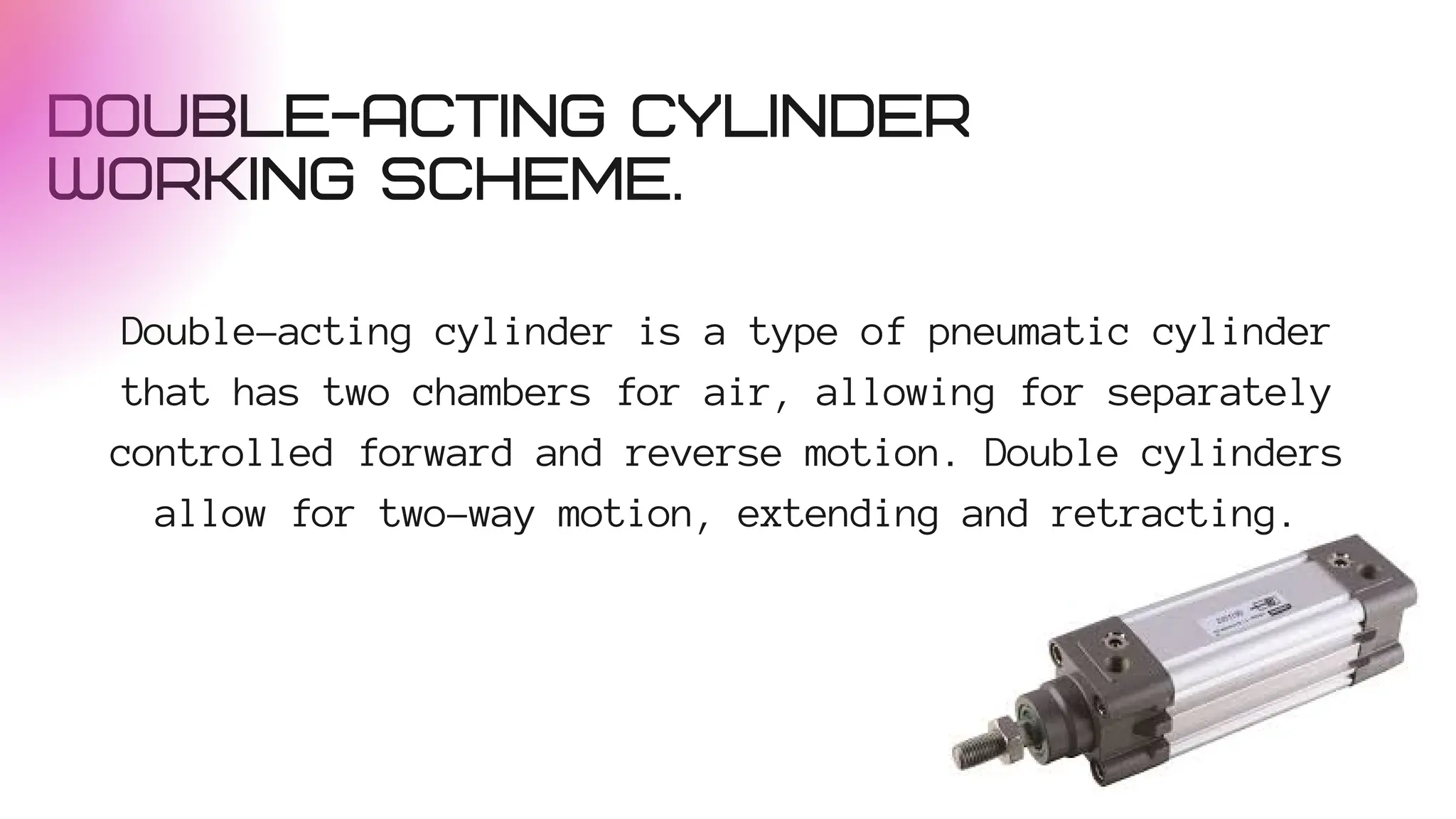
DOUBLE-ACTING CYLINDER
WORKING SCHEME.
Double-actingcylinder is a type of pneumatic cylinder
that has two chambers for air, allowing for separately
controlled forward and reverse motion. Double cylinders
allow for two-way motion, extending and retracting.
14.
APPLICATIONS IN MARINESYSTEMS
Rudder Control: Pneumatic cylinders are used to move a ship's
rudder to turn.The main function of rudder is Changing the
direction of the ship. By turning the rudder, the water flow
around it will create a lateral force that changes the
direction of the ship.
CONVERT LINEAR MOTIONTO
ROTATION
The working principle The piston that moves back and
forth in the cylinder will be connected to the drive
shaft. When pressurized air enters the cylinder, the
piston moves, and this linear motion is transmitted to
the gear box or drive shaft which converts it into
rotational motion.
17.
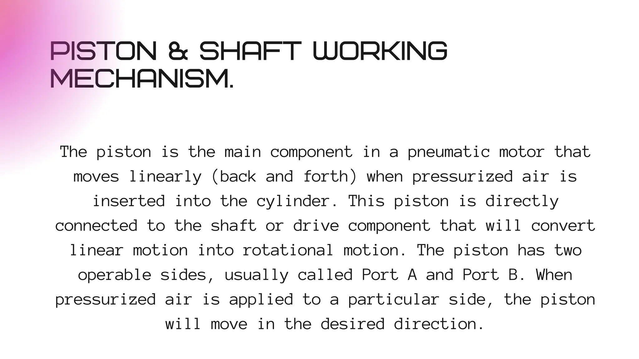
PISTON & SHAFTWORKING
MECHANISM.
The piston is the main component in a pneumatic motor that
moves linearly (back and forth) when pressurized air is
inserted into the cylinder. This piston is directly
connected to the shaft or drive component that will convert
linear motion into rotational motion. The piston has two
operable sides, usually called Port A and Port B. When
pressurized air is applied to a particular side, the piston
will move in the desired direction.
18.
PNEUMATIC MOTOR APPLICATIONS
WITHPISTON & SHAFT
1.Windlass: A pneumatic motor is used to drive the windlass drum. The rotational motion
generated by the shaft is used to lift the anchor or ship's rope.
2.Conveyor: A pneumatic motor drives the conveyor belt system. The rotational motion
generated by the shaft is used to rotate the conveyor drum, which in turn drives the
material carrying belt.
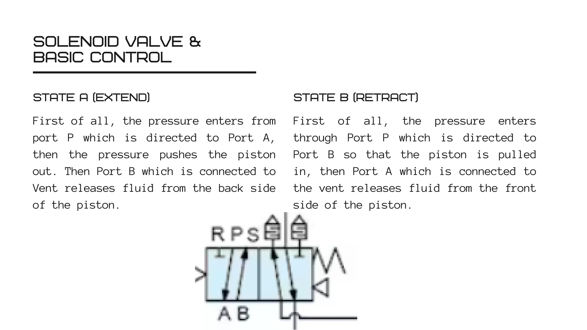
SOLENOID VALVE &
BASICCONTROL
First of all, the pressure enters from
port P which is directed to Port A,
then the pressure pushes the piston
out. Then Port B which is connected to
Vent releases fluid from the back side
of the piston.
STATE A (EXTEND)
First of all, the pressure enters
through Port P which is directed to
Port B so that the piston is pulled
in, then Port A which is connected to
the vent releases fluid from the front
side of the piston.
STATE B (RETRACT)
21.
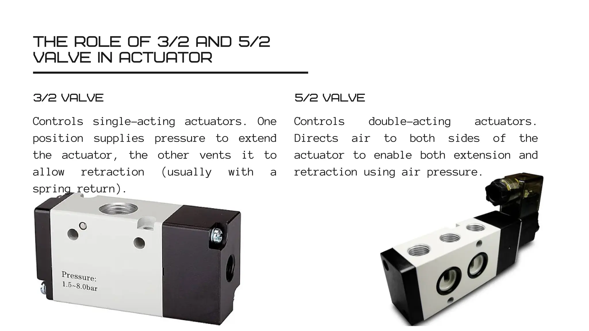
THE ROLE OF3/2 AND 5/2
VALVE IN ACTUATOR
Controls single-acting actuators. One
position supplies pressure to extend
the actuator, the other vents it to
allow retraction (usually with a
spring return).
3/2 VALVE
Controls double-acting actuators.
Directs air to both sides of the
actuator to enable both extension and
retraction using air pressure.
5/2 VALVE
ISO & DIN
isan international non-governmental
organization that develops and
publishes international standards for
a variety of fields, including
engineering, technology, safety, and
efficiency.Meanwhile, the one used in
this discussion is ISO 1219, which is
a standard that regulates graphic
symbols for fluid systems (hydraulic
and pneumatic).
ISO (INTERNATIONAL ORGANIZATION
FOR STANDARDIZATION)
DIN stands for "Deutsches Institut für
Normung", which is the German
Institute for Standardization. DIN is
responsible for developing technical
standards in various industrial
fields, including mechanical
engineering, electrical engineering,
automotive engineering, and others.
DIN
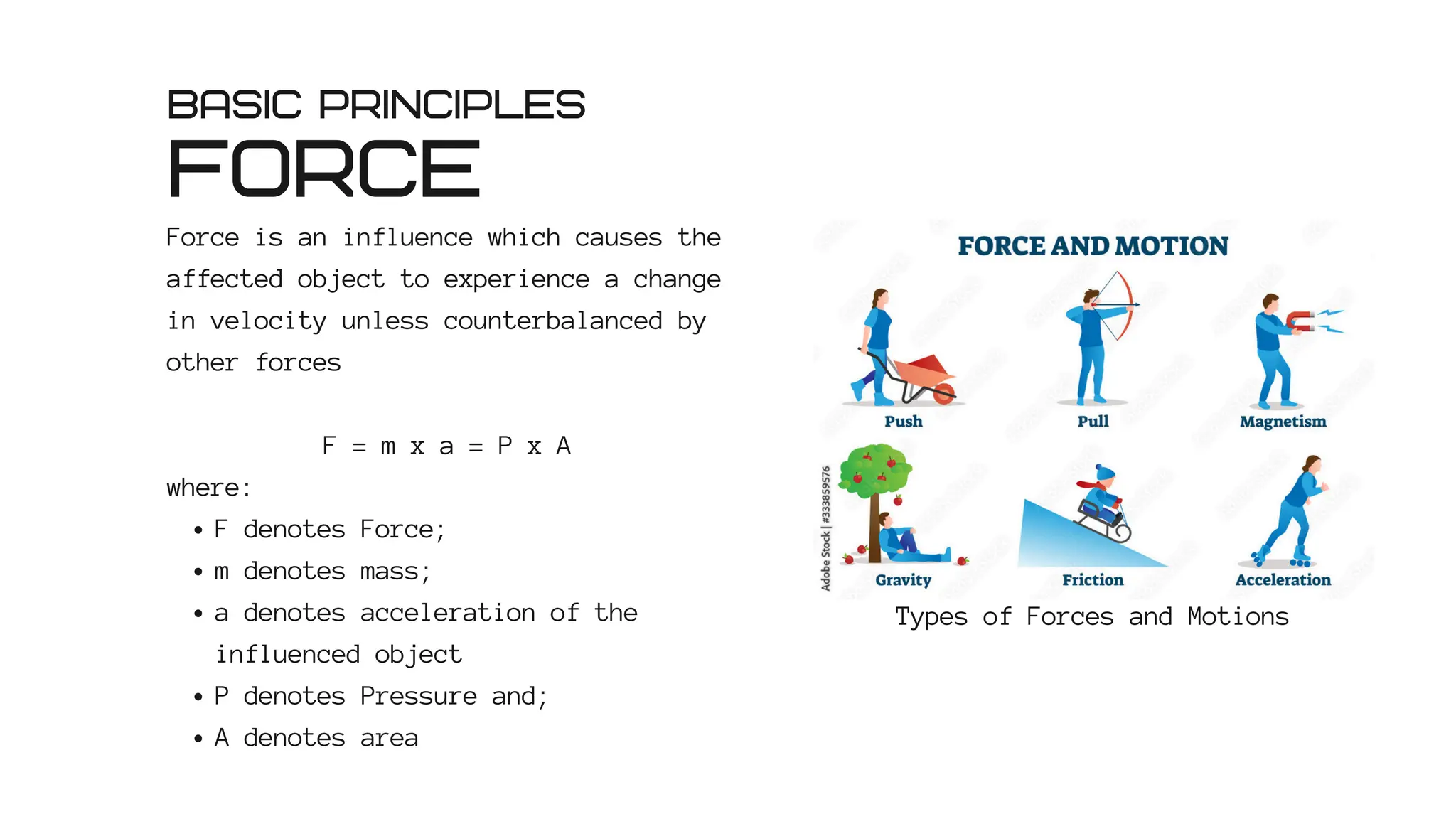
FORCE
Force is aninfluence which causes the
affected object to experience a change
in velocity unless counterbalanced by
other forces
F = m x a = P x A
where:
F denotes Force;
m denotes mass;
a denotes acceleration of the
influenced object
P denotes Pressure and;
A denotes area
BASIC PRINCIPLES
Types of Forces and Motions
28.
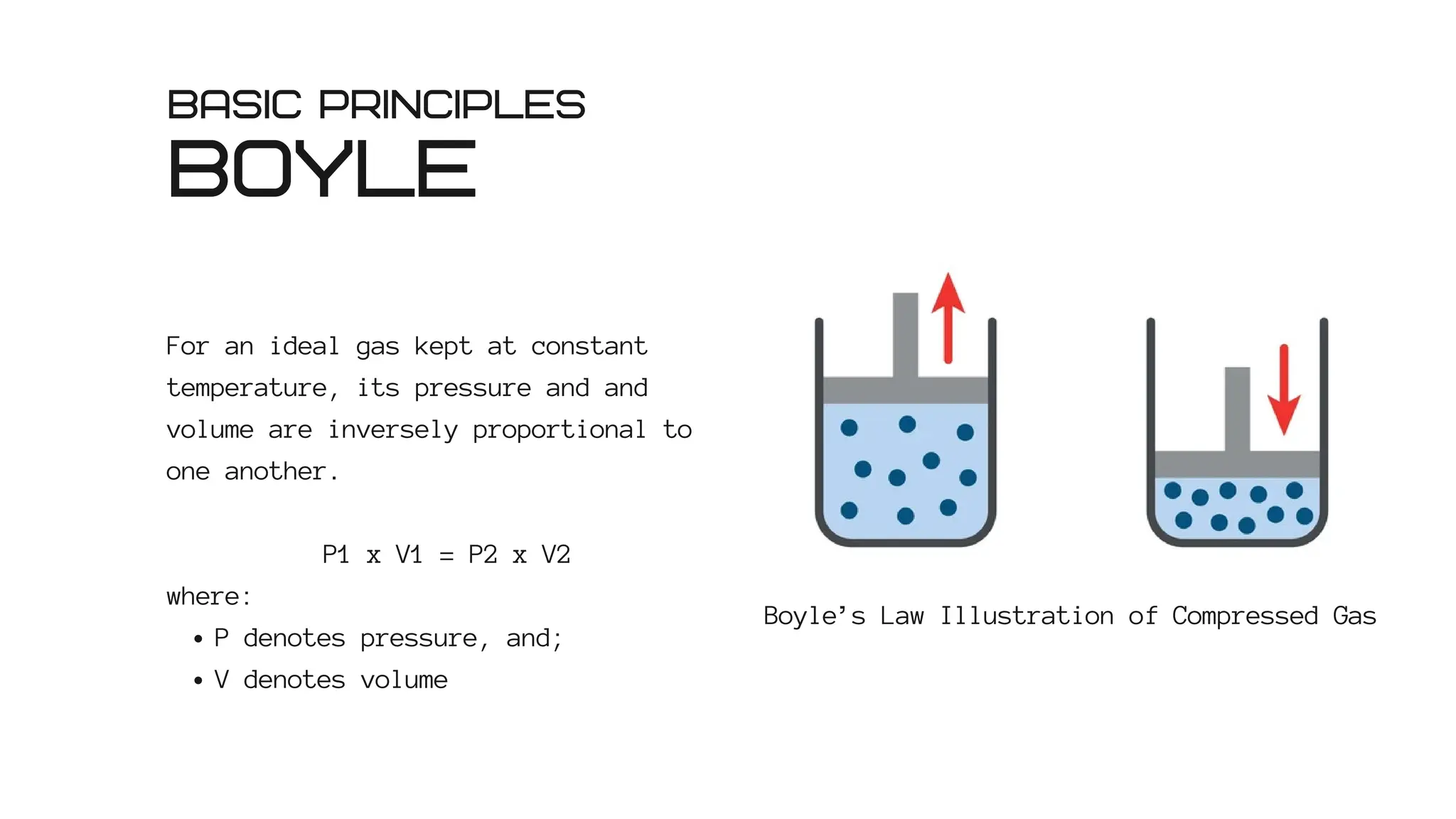
BOYLE
For an idealgas kept at constant
temperature, its pressure and and
volume are inversely proportional to
one another.
P1 x V1 = P2 x V2
where:
P denotes pressure, and;
V denotes volume
BASIC PRINCIPLES
Boyle’s Law Illustration of Compressed Gas
29.
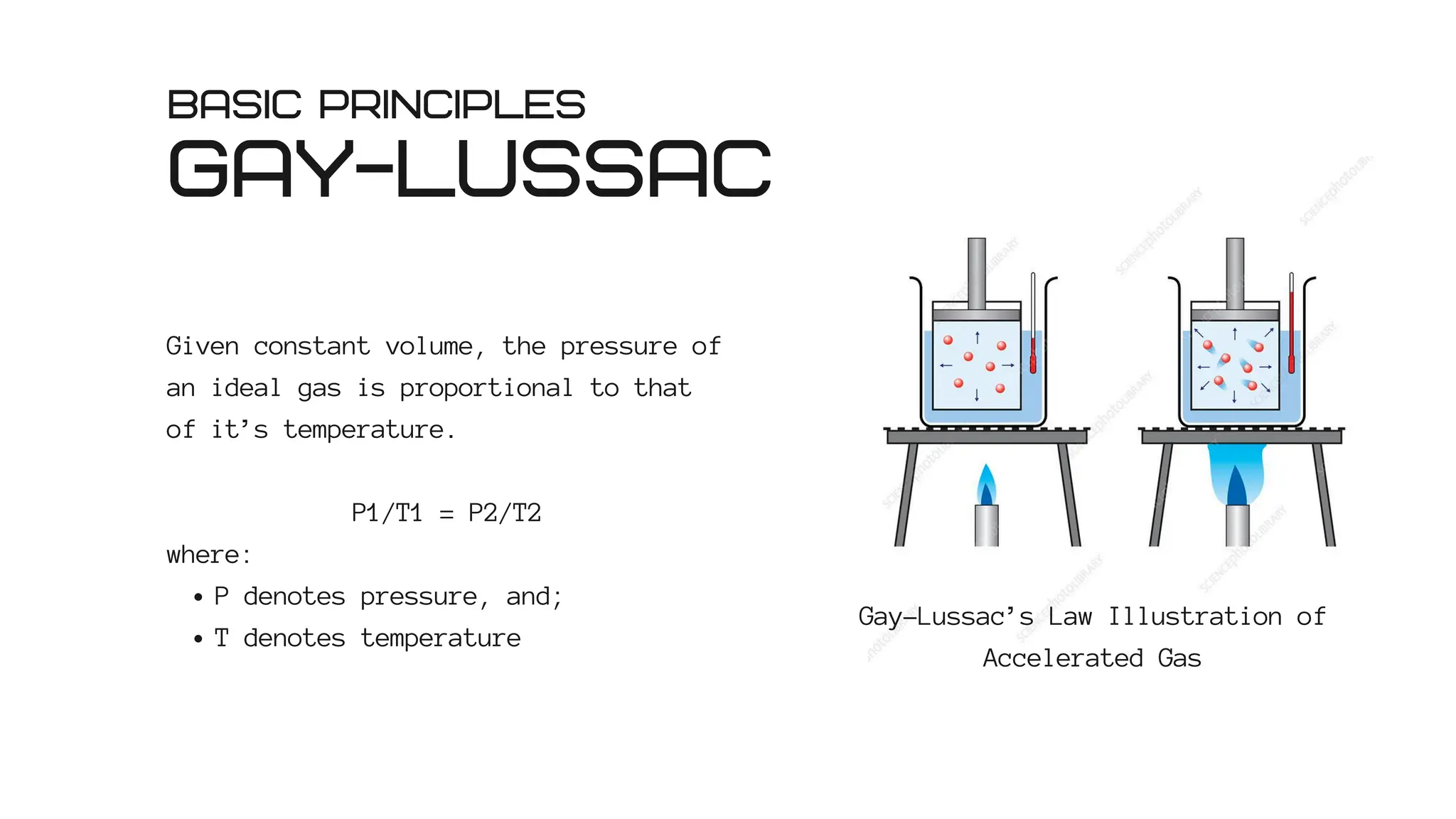
GAY-LUSSAC
Given constant volume,the pressure of
an ideal gas is proportional to that
of it’s temperature.
P1/T1 = P2/T2
where:
P denotes pressure, and;
T denotes temperature
BASIC PRINCIPLES
Gay-Lussac’s Law Illustration of
Accelerated Gas
30.
EXAMPLE
A pneumatic systemis poised to generate a certain amount of force using
pressurized air. Said pressurized air clocks in a pressure of 1.536 bar,
traversing the length of a 6.5 cm pipe, with a radius of 13 mm at 0.268
seconds. Thus, determine the amount of force produced and the velocity at
which the pressurized air travels.
CALCULATION
Known:
P = 1.563 bar = 156300 N/m2
L = 6.5 cm = 0.065 m
r = 13 mm = 0.013 m
t = 0.268 seconds
Answer:
F = P x A
A = πr2 = 3.14 x 0.000169
A = 0.000531
F = 153600 N/m2 x 0.000531 m2
F = 81.51 N
V = L/t = 0.065 m/0.268 s
V = 0.243 m/s
31.
EXAMPLE
In a certainpneumatic experiment with a double acting actuator, flow
control opening 5 is used. Receiver pressure and system inlet is determined
to be 0.5 bar. Similarly, pressures when the actuator extends and retracts
are also 0.5 bar; while their velocities are 0.2 and 0.33 seconds,
respectively. With an actuating length of 10.8 cm and cylinder diameter of
9 mm, determine the required force and actuator velocity.
CALCULATION
Known:
P = 0.5 bar = 50000 N/m2
L = 10.8 cm = 0.108 m
r = 4.5 mm = 0.0045 m
t = 0.2 seconds
Answer:
F = P x A
A = πr2 = 3.14 x 0.00002025
A = 0.000063585 m2
F = 50000 N/m2 x 0.000063585 m2
F = 3.179 N
V = L/t = 0.108 m/0.2 s
V = 0.054 m/s
WHY?
Pneumatic systems areoften used on ships due to their safety and efficiency. Compressed
air is non flammable and spark free, as per SOLAS standards for hazardous areas such as
engine rooms and fuel tanks. Its components are designed with marine-grade materials
(stainless steel, brass) that resist sea air corrosion, engine vibration, and extreme
temperatures (-20°C to 70°C). The system is also efficient as it utilizes the available
compressed air infrastructure (e.g. for engine starting), with actuator response crucial
for emergency applications such as watertight doors. Its simple design makes it low
maintenance and tolerant of particle contamination.
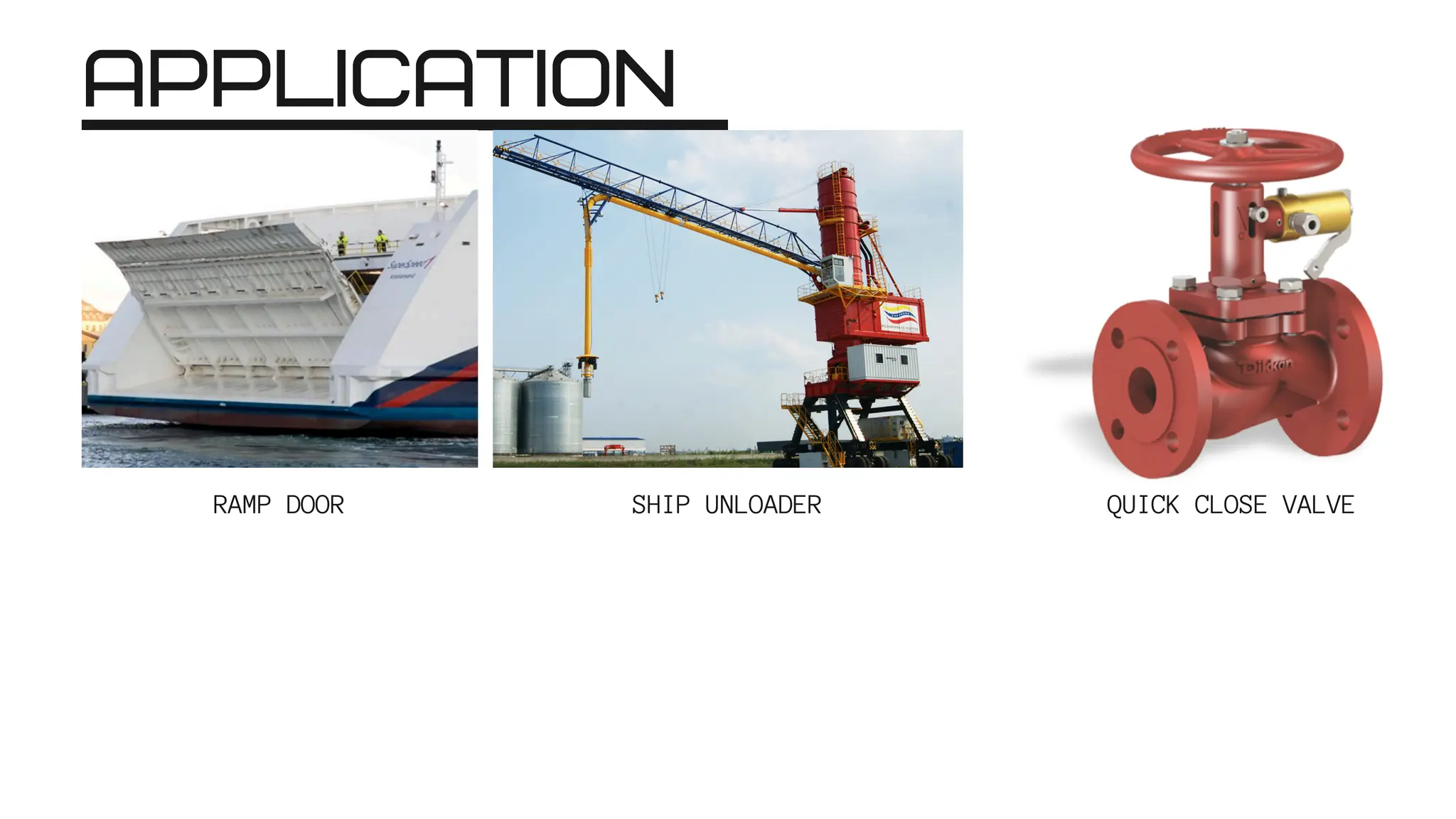
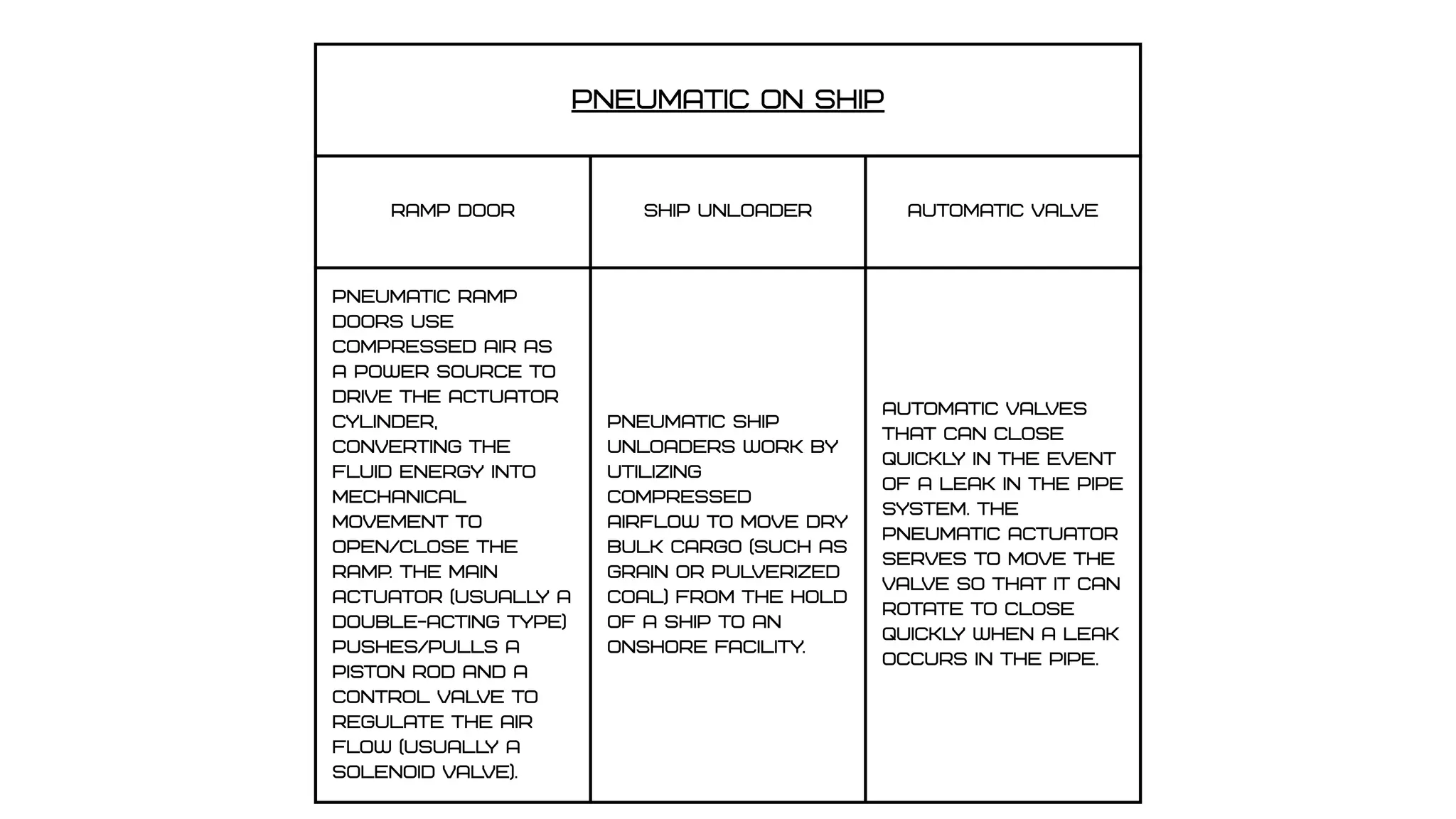
PNEUMATIC ON SHIP
RampDOOR ship unloader automatic valve
Pneumatic ramp
doors use
compressed air as
a power source to
drive the actuator
cylinder,
converting the
fluid energy into
mechanical
movement to
open/close the
ramp. The main
actuator (usuall
y a
double-acting type)
pushes/pulls a
piston rod and a
control valve to
regulate the air
flow (usuall
y a
solenoid valve).
Pneumatic Ship
Unloaders work by
utilizing
compressed
airflow to move dry
bulk cargo (such as
grain or pulverized
coal) from the hold
of a ship to an
onshore facility.
Automatic valves
that can close
quickl
y in the event
of a leak in the pipe
system. The
pneumatic actuator
serves to move the
valve so that it can
rotate to close
quickl
y when a leak
occurs in the pipe.