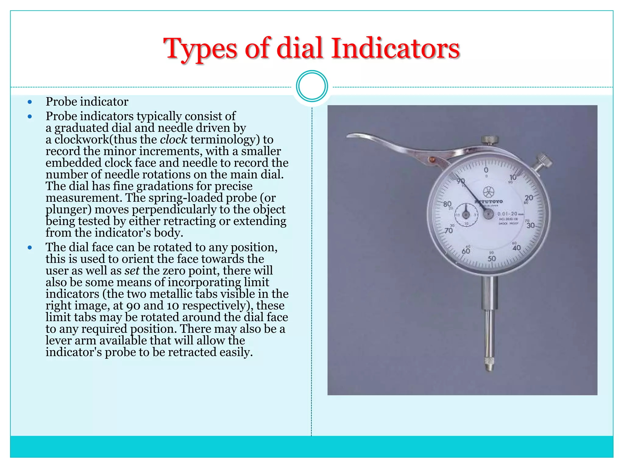
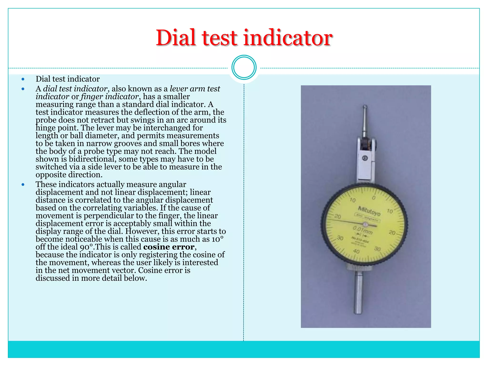
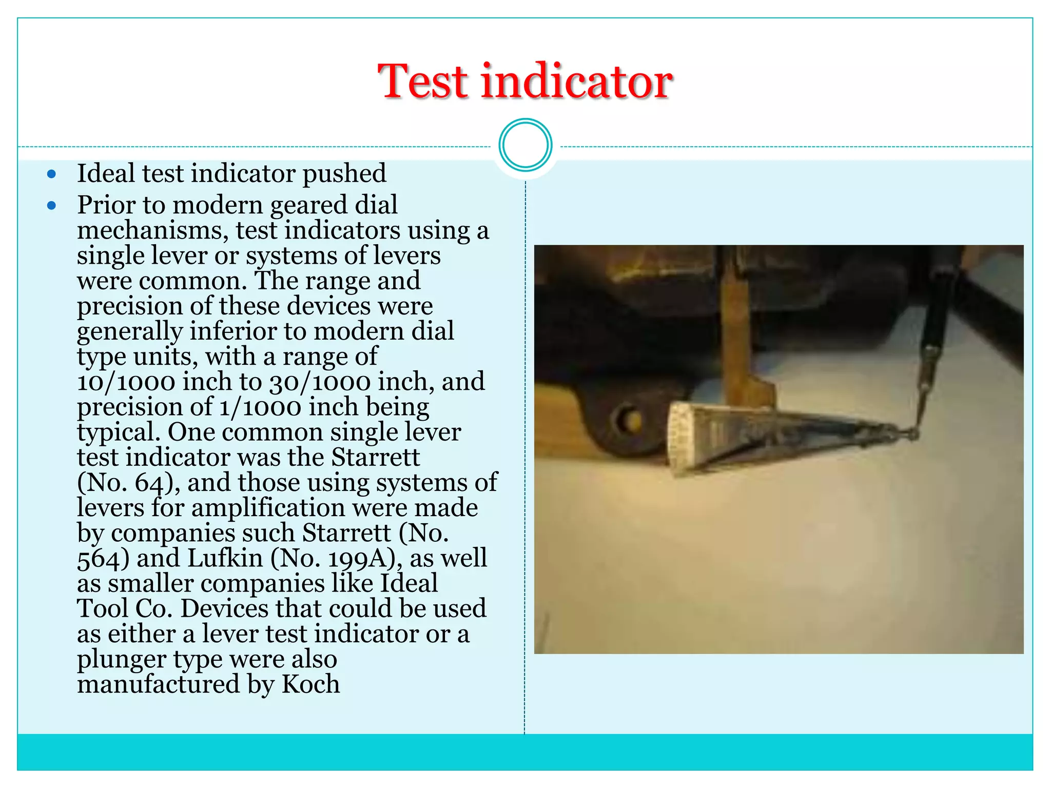
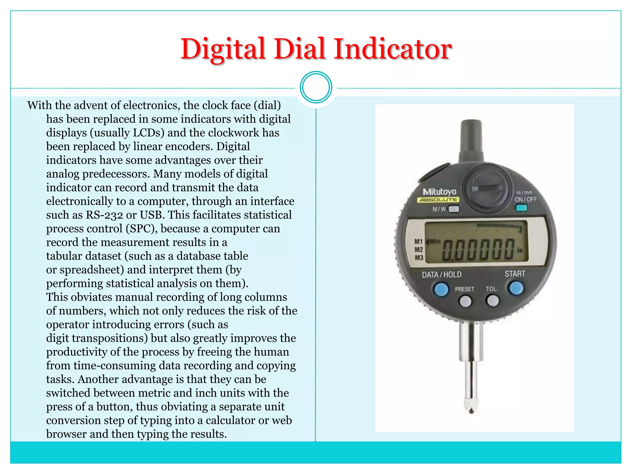
S U B J E C T : - E M E
G R O U P : 5 8 , 5 9 , 6 1
1 ) S U F I Y A
2 ) R A N G E S H
3 ) P R A D E S H
Dial Indicator
Introduction
 In various contexts of science, technology, and manufacturing (such as machining, fabricating,
and additive manufacturing), an indicator is any of various instruments used to accurately
measure small distances and angles, and amplify them to make them more obvious. The name
comes from the concept of indicating to the user that which their naked eye cannot discern;
such as the presence, or exact quantity, of some small distance (for example, a small height
difference between two flat surfaces, a slight lack of concentricity between two cylinders, or
other small physical deviations).
 Many indicators have a dial display, in which a needle points to graduations in a circular array
around the dial. Such indicators, of which there are several types, are often called dial
indicators.
 Other types of indicator include mechanical devices with cantilevered pointers and electronic
devices with digital displays.
 Indicators may be used to check the variation in tolerance during the inspection process of a
machined part, measure the deflection of a beam or ring under laboratory conditions, as well as
many other situations where a small measurement needs to be registered or indicated. Dial
indicators typically measure ranges from 0.25 mm to 300 mm (0.015in to 12.0in), with
graduations of 0.001 mm to 0.01 mm (metric) or 0.00005in to 0.001in (imperial/customary).
 Various names are used for indicators of different types and purposes, including dial
gauge, clock, probe indicator, pointer, test indicator, dial test indicator, drop
indicator, plunger indicator, and others.
Principle
Indicators inherently provide relative measure only.
But given that suitable references are used (for
example, gauge blocks), they often allow a practical
equivalent of absolute measure, with periodic
recalibration against the references. However, the
user must know how to use them properly and
understand how in some situations, their
measurements will still be relative rather than
absolute because of factors such as cosine error
(discussed later).
Application
 To check for Lateral run-out when fitting a new disc to an automotive disc brake. Lateral Run-out (lack
of perpendicularity between the disc surface and the shaft axis, caused by deformations or more
frequently by a lack of proper cleaning of the mounting surface of hub. This Run-out can produce
brake pedal pulsations, vibration of the vehicle when brakes are applied and can induce uneven wear
of the disc. The Lateral Run-out can be caused by uneven torque, damaged studs, or a burr or rust
between the hub and rotor. This variation can be tested with a dial indicator, and most times the
variation can be more or less cancelled by reinstalling the disc in other position, so that the tolerances
of both the hub and the disc tend to cancel each other. To reduce the Runout, the disc is mounted and
torqued to half the specified torque (as there is no wheel to distribute stresses) then a dial Indicator is
placed against the braking surface and the face of the dial is centered, the disc is slowly rotated by
hand and the maximum deviation is noted. If the maximum Run-out is within the maximum allowed
Run-out specified in the manual, the disc can be installed at that position, but if the technician wants
to minimize the total lateral Run-out, other around the clock positions can be tried. Excessive Runout
can rapidly ruin the disc if it exceeds the specified tolerance (typically up to 0.004",4 mils but most
discs can attain less than 0.002" or 0.05mm or less if installed at the optimum position) In
a quality environment to check for consistency and accuracy in the manufacturing process.
 On the workshop floor to initially set up or calibrate a machine, prior to a production run.
 By toolmakers (such as moldmakers) in the process of manufacturing precision tooling.
 In metal engineering workshops, where a typical application is the centering of a lathe's workpiece in a
four jaw chuck. The dial indicator is used to indicate the run out (the misalignment between the
workpiece's axis of rotational symmetry and the axis of rotation of the spindle) of the workpiece, with
the ultimate aim of reducing it to a suitably small range using small chuck jaw adjustments.
 In areas other than manufacturing where accurate measurements need to be recorded
Types of dial Indicators
 Probe indicator
 Probe indicators typically consist of
a graduated dial and needle driven by
a clockwork(thus the clock terminology) to
record the minor increments, with a smaller
embedded clock face and needle to record the
number of needle rotations on the main dial.
The dial has fine gradations for precise
measurement. The spring-loaded probe (or
plunger) moves perpendicularly to the object
being tested by either retracting or extending
from the indicator's body.
 The dial face can be rotated to any position,
this is used to orient the face towards the
user as well as set the zero point, there will
also be some means of incorporating limit
indicators (the two metallic tabs visible in the
right image, at 90 and 10 respectively), these
limit tabs may be rotated around the dial face
to any required position. There may also be a
lever arm available that will allow the
indicator's probe to be retracted easily.
Dial test indicator
 Dial test indicator
 A dial test indicator, also known as a lever arm test
indicator or finger indicator, has a smaller
measuring range than a standard dial indicator. A
test indicator measures the deflection of the arm, the
probe does not retract but swings in an arc around its
hinge point. The lever may be interchanged for
length or ball diameter, and permits measurements
to be taken in narrow grooves and small bores where
the body of a probe type may not reach. The model
shown is bidirectional, some types may have to be
switched via a side lever to be able to measure in the
opposite direction.
 These indicators actually measure angular
displacement and not linear displacement; linear
distance is correlated to the angular displacement
based on the correlating variables. If the cause of
movement is perpendicular to the finger, the linear
displacement error is acceptably small within the
display range of the dial. However, this error starts to
become noticeable when this cause is as much as 10°
off the ideal 90°.This is called cosine error,
because the indicator is only registering the cosine of
the movement, whereas the user likely is interested
in the net movement vector. Cosine error is
discussed in more detail below.
Test indicator
 Ideal test indicator pushed
 Prior to modern geared dial
mechanisms, test indicators using a
single lever or systems of levers
were common. The range and
precision of these devices were
generally inferior to modern dial
type units, with a range of
10/1000 inch to 30/1000 inch, and
precision of 1/1000 inch being
typical. One common single lever
test indicator was the Starrett
(No. 64), and those using systems of
levers for amplification were made
by companies such Starrett (No.
564) and Lufkin (No. 199A), as well
as smaller companies like Ideal
Tool Co. Devices that could be used
as either a lever test indicator or a
plunger type were also
manufactured by Koch
Digital Dial Indicator
With the advent of electronics, the clock face (dial)
has been replaced in some indicators with digital
displays (usually LCDs) and the clockwork has
been replaced by linear encoders. Digital
indicators have some advantages over their
analog predecessors. Many models of digital
indicator can record and transmit the data
electronically to a computer, through an interface
such as RS-232 or USB. This facilitates statistical
process control (SPC), because a computer can
record the measurement results in a
tabular dataset (such as a database table
or spreadsheet) and interpret them (by
performing statistical analysis on them).
This obviates manual recording of long columns
of numbers, which not only reduces the risk of the
operator introducing errors (such as
digit transpositions) but also greatly improves the
productivity of the process by freeing the human
from time-consuming data recording and copying
tasks. Another advantage is that they can be
switched between metric and inch units with the
press of a button, thus obviating a separate unit
conversion step of typing into a calculator or web
browser and then typing the results.
Contact point (tip) types
 Plunger (drop) indicator tips
 On drop indicators, the tip of the probe usually may be
interchanged with a range of shapes and sizes depending
on the application. The tips typically are attached with
either a #4-48 or an M2.5 screw thread. Spherical tips
are often used to give point contact. Cylindrical and flat
tips are also used as the need arises. Needle-shaped tips
allow the tip to enter a small hole or slot. Accessory sets
of tips are sold separately and inexpensively, so that even
indicators that have no set of tips may be augmented
with a new set.
Dial test indicator tips
 Dial test indicators, whose tips swing in an arc rather than plunging linearly, usually
have spherical tips. This shape gives pointcontact, allowing for consistent
measurements as the tip moves through its arc (via consistent offset distance from
ball surface to center point, regardless of ball contact angle with the measured
surface). Several spherical diameters are commercially offered; 1mm, 2mm, and
3mm are the standard sizes.
 Despite the advantage just mentioned (regarding contact angle irrelevance) of the
ball (sphere) itself, the contact angle of the lever overall does matter. On most DTIs
it must be parallel (0°, 180°) to the surface being measured in order for the
measurement to be truly accurate, that is, for the magnitude of the dial reading to
reflect the true tip movement distance without cosine error. In other words, the path
of the tip's movement must coincide with the vector that is being measured;
otherwise, only the cosine of the vector is being measured (yielding the error called
cosine error). In such cases the indicator may still be useful, but an offset (multiplier
or correction factor) must be applied to achieve a correct measurement (where the
measurement is absolute rather than merely comparative). (This fact applies to the
angle between the lever and the part, not to the angle between the lever and the DTI
body, which is adjustable on most DTIs.) The same principle is also employed
with CMM touch trigger probes (TTPs), where the machine (when used correctly)
adjusts its ball-offset compensation to account for any difference between the
approach vector and the surface vector.
Advantages of Dial Indicator
 Ease of reading a dial indicator is the biggest advantage over other conventional types of linear measuring
instruments, which require degree of skill and considerable practice before proficiency in their use can be
attained.
(2) This is extremely useful for quality control in the inspection room and unskilled labour can be employed
for its use. Once a dial indicator has been set up, the operator has only to refer to the work and observe the
position of the pointer.
(3) It has made it unnecessary to depend upon the uncertain human ability to ‘feel’ or judge the variations in
pressure when a conventional gauge is applied to the work, as the measuring pressure between the spindle and
work automatically remains constant. This feature is specially important in the measurement of light
materials. In the case of other gauges, the nerves of the inspector tell him, how a gauge feels on work and this
can’t be same in case of any two persons. Thus wherever we have part tolerances in thousands, other gauges
are not so reliable.
(4) This is best suited for precision dimensional control, where tolerances are very small and by its use
dimensions can be easily controlled in mass production.
(5) This is not subjected to problems of gauge wear and temperature variations etc. as in the case of
conventional gauges.
(6) These are able to inspect dimensional variations which are impossible to be detected even by the
conventional gauges.
(7) The speed, adaptability, and positive visibility of dial indicator gauges, in addition to their accuracy and
economy place them in vanguard of precision measurement.
(8) It is possible to use it for many different measurements by means of a few simple attachments, thus
making it more versatile.
(9) By its intelligent use, a large and costly collection of specially made gauges can be avoided.
(10) Conditions which influence the accuracy of a specified dimension and which cannot be detected by
conventional gauges are readily discovered by dial indicators e.g. out of roundness, taper etc.
(11) Combination of dimensions having a certain relation to each other can be easily inspected by the proper
design of multiple inspection gauges, thereby saving time and avoiding the necessity of using different
Disadvantages
 Vibration: vibration tends to be greatly amplified at the indicator itself, to the
point where it becomes difficult to read accurately, or even impossible to read at all.
 Tilted Indicator: Space constraints may force you to install the indicator at an
angle to the reference surface being measured. This tilting will lead to a significant
error in the readings as the movement being measured results in a significantly
reduced travel of the indicator stem
 Parallax Effect and Reading Error: If space constraints do not allow you to
view the face of your dial indicator squarely, you may misread the indicator by
several thousandths of an inch. Also, if the travel of the indicator stem is not
observed all the way around, a huge reading error
 Indicator Resolution: If a delicate measurement task is undertaken, such as
measuring the effect of machine frame distortion by observing the angular changes
at the coupling, it must be remembered that these effects dwindle through
mechanical looseness and the fact that the shaft is midway between the feet
laterally; thus, when one machine foot is loosened, the effect on the shaft is halved.
 Indicator Hysteresis: Hysteresis of the indicator may also conspire to reduce the
accuracy of your readings. Hysteresis is friction of the internal moving parts of the
indicator mechanism.
 End Float (axial play): End float, or shaft end play, can bedevil a face indicator.
This is particularly true on machines with journal bearings or sleeve bearings that
permit a certain amount of axial play to occur in the shaft as it is rotated. This will
play havoc with the accuracy of a face (or axially mounted) indicator.
Reference
 https://en.wikipedia.org/wiki/Indicator_(distance_
amplifying_instrument)
 http://what-when-how.com/metrology/advantages-
of-dial-indicators-metrology/
 https://ludeca.com/blog/tag/disadvantages-dial-
indicators/
Thanking you for joined us
S U BJE CT : E M E
G R OUP : - 5 8 , 5 9, 61
1 ) S U FI YA N
2 ) R A NG ESH
3 ) P R A DES H

Dial indicator

  • 1.
    S U BJ E C T : - E M E G R O U P : 5 8 , 5 9 , 6 1 1 ) S U F I Y A 2 ) R A N G E S H 3 ) P R A D E S H Dial Indicator
  • 2.
    Introduction  In variouscontexts of science, technology, and manufacturing (such as machining, fabricating, and additive manufacturing), an indicator is any of various instruments used to accurately measure small distances and angles, and amplify them to make them more obvious. The name comes from the concept of indicating to the user that which their naked eye cannot discern; such as the presence, or exact quantity, of some small distance (for example, a small height difference between two flat surfaces, a slight lack of concentricity between two cylinders, or other small physical deviations).  Many indicators have a dial display, in which a needle points to graduations in a circular array around the dial. Such indicators, of which there are several types, are often called dial indicators.  Other types of indicator include mechanical devices with cantilevered pointers and electronic devices with digital displays.  Indicators may be used to check the variation in tolerance during the inspection process of a machined part, measure the deflection of a beam or ring under laboratory conditions, as well as many other situations where a small measurement needs to be registered or indicated. Dial indicators typically measure ranges from 0.25 mm to 300 mm (0.015in to 12.0in), with graduations of 0.001 mm to 0.01 mm (metric) or 0.00005in to 0.001in (imperial/customary).  Various names are used for indicators of different types and purposes, including dial gauge, clock, probe indicator, pointer, test indicator, dial test indicator, drop indicator, plunger indicator, and others.
  • 3.
    Principle Indicators inherently providerelative measure only. But given that suitable references are used (for example, gauge blocks), they often allow a practical equivalent of absolute measure, with periodic recalibration against the references. However, the user must know how to use them properly and understand how in some situations, their measurements will still be relative rather than absolute because of factors such as cosine error (discussed later).
  • 4.
    Application  To checkfor Lateral run-out when fitting a new disc to an automotive disc brake. Lateral Run-out (lack of perpendicularity between the disc surface and the shaft axis, caused by deformations or more frequently by a lack of proper cleaning of the mounting surface of hub. This Run-out can produce brake pedal pulsations, vibration of the vehicle when brakes are applied and can induce uneven wear of the disc. The Lateral Run-out can be caused by uneven torque, damaged studs, or a burr or rust between the hub and rotor. This variation can be tested with a dial indicator, and most times the variation can be more or less cancelled by reinstalling the disc in other position, so that the tolerances of both the hub and the disc tend to cancel each other. To reduce the Runout, the disc is mounted and torqued to half the specified torque (as there is no wheel to distribute stresses) then a dial Indicator is placed against the braking surface and the face of the dial is centered, the disc is slowly rotated by hand and the maximum deviation is noted. If the maximum Run-out is within the maximum allowed Run-out specified in the manual, the disc can be installed at that position, but if the technician wants to minimize the total lateral Run-out, other around the clock positions can be tried. Excessive Runout can rapidly ruin the disc if it exceeds the specified tolerance (typically up to 0.004",4 mils but most discs can attain less than 0.002" or 0.05mm or less if installed at the optimum position) In a quality environment to check for consistency and accuracy in the manufacturing process.  On the workshop floor to initially set up or calibrate a machine, prior to a production run.  By toolmakers (such as moldmakers) in the process of manufacturing precision tooling.  In metal engineering workshops, where a typical application is the centering of a lathe's workpiece in a four jaw chuck. The dial indicator is used to indicate the run out (the misalignment between the workpiece's axis of rotational symmetry and the axis of rotation of the spindle) of the workpiece, with the ultimate aim of reducing it to a suitably small range using small chuck jaw adjustments.  In areas other than manufacturing where accurate measurements need to be recorded
  • 5.
    Types of dialIndicators  Probe indicator  Probe indicators typically consist of a graduated dial and needle driven by a clockwork(thus the clock terminology) to record the minor increments, with a smaller embedded clock face and needle to record the number of needle rotations on the main dial. The dial has fine gradations for precise measurement. The spring-loaded probe (or plunger) moves perpendicularly to the object being tested by either retracting or extending from the indicator's body.  The dial face can be rotated to any position, this is used to orient the face towards the user as well as set the zero point, there will also be some means of incorporating limit indicators (the two metallic tabs visible in the right image, at 90 and 10 respectively), these limit tabs may be rotated around the dial face to any required position. There may also be a lever arm available that will allow the indicator's probe to be retracted easily.
  • 6.
    Dial test indicator Dial test indicator  A dial test indicator, also known as a lever arm test indicator or finger indicator, has a smaller measuring range than a standard dial indicator. A test indicator measures the deflection of the arm, the probe does not retract but swings in an arc around its hinge point. The lever may be interchanged for length or ball diameter, and permits measurements to be taken in narrow grooves and small bores where the body of a probe type may not reach. The model shown is bidirectional, some types may have to be switched via a side lever to be able to measure in the opposite direction.  These indicators actually measure angular displacement and not linear displacement; linear distance is correlated to the angular displacement based on the correlating variables. If the cause of movement is perpendicular to the finger, the linear displacement error is acceptably small within the display range of the dial. However, this error starts to become noticeable when this cause is as much as 10° off the ideal 90°.This is called cosine error, because the indicator is only registering the cosine of the movement, whereas the user likely is interested in the net movement vector. Cosine error is discussed in more detail below.
  • 7.
    Test indicator  Idealtest indicator pushed  Prior to modern geared dial mechanisms, test indicators using a single lever or systems of levers were common. The range and precision of these devices were generally inferior to modern dial type units, with a range of 10/1000 inch to 30/1000 inch, and precision of 1/1000 inch being typical. One common single lever test indicator was the Starrett (No. 64), and those using systems of levers for amplification were made by companies such Starrett (No. 564) and Lufkin (No. 199A), as well as smaller companies like Ideal Tool Co. Devices that could be used as either a lever test indicator or a plunger type were also manufactured by Koch
  • 8.
    Digital Dial Indicator Withthe advent of electronics, the clock face (dial) has been replaced in some indicators with digital displays (usually LCDs) and the clockwork has been replaced by linear encoders. Digital indicators have some advantages over their analog predecessors. Many models of digital indicator can record and transmit the data electronically to a computer, through an interface such as RS-232 or USB. This facilitates statistical process control (SPC), because a computer can record the measurement results in a tabular dataset (such as a database table or spreadsheet) and interpret them (by performing statistical analysis on them). This obviates manual recording of long columns of numbers, which not only reduces the risk of the operator introducing errors (such as digit transpositions) but also greatly improves the productivity of the process by freeing the human from time-consuming data recording and copying tasks. Another advantage is that they can be switched between metric and inch units with the press of a button, thus obviating a separate unit conversion step of typing into a calculator or web browser and then typing the results.
  • 9.
    Contact point (tip)types  Plunger (drop) indicator tips  On drop indicators, the tip of the probe usually may be interchanged with a range of shapes and sizes depending on the application. The tips typically are attached with either a #4-48 or an M2.5 screw thread. Spherical tips are often used to give point contact. Cylindrical and flat tips are also used as the need arises. Needle-shaped tips allow the tip to enter a small hole or slot. Accessory sets of tips are sold separately and inexpensively, so that even indicators that have no set of tips may be augmented with a new set.
  • 10.
    Dial test indicatortips  Dial test indicators, whose tips swing in an arc rather than plunging linearly, usually have spherical tips. This shape gives pointcontact, allowing for consistent measurements as the tip moves through its arc (via consistent offset distance from ball surface to center point, regardless of ball contact angle with the measured surface). Several spherical diameters are commercially offered; 1mm, 2mm, and 3mm are the standard sizes.  Despite the advantage just mentioned (regarding contact angle irrelevance) of the ball (sphere) itself, the contact angle of the lever overall does matter. On most DTIs it must be parallel (0°, 180°) to the surface being measured in order for the measurement to be truly accurate, that is, for the magnitude of the dial reading to reflect the true tip movement distance without cosine error. In other words, the path of the tip's movement must coincide with the vector that is being measured; otherwise, only the cosine of the vector is being measured (yielding the error called cosine error). In such cases the indicator may still be useful, but an offset (multiplier or correction factor) must be applied to achieve a correct measurement (where the measurement is absolute rather than merely comparative). (This fact applies to the angle between the lever and the part, not to the angle between the lever and the DTI body, which is adjustable on most DTIs.) The same principle is also employed with CMM touch trigger probes (TTPs), where the machine (when used correctly) adjusts its ball-offset compensation to account for any difference between the approach vector and the surface vector.
  • 11.
    Advantages of DialIndicator  Ease of reading a dial indicator is the biggest advantage over other conventional types of linear measuring instruments, which require degree of skill and considerable practice before proficiency in their use can be attained. (2) This is extremely useful for quality control in the inspection room and unskilled labour can be employed for its use. Once a dial indicator has been set up, the operator has only to refer to the work and observe the position of the pointer. (3) It has made it unnecessary to depend upon the uncertain human ability to ‘feel’ or judge the variations in pressure when a conventional gauge is applied to the work, as the measuring pressure between the spindle and work automatically remains constant. This feature is specially important in the measurement of light materials. In the case of other gauges, the nerves of the inspector tell him, how a gauge feels on work and this can’t be same in case of any two persons. Thus wherever we have part tolerances in thousands, other gauges are not so reliable. (4) This is best suited for precision dimensional control, where tolerances are very small and by its use dimensions can be easily controlled in mass production. (5) This is not subjected to problems of gauge wear and temperature variations etc. as in the case of conventional gauges. (6) These are able to inspect dimensional variations which are impossible to be detected even by the conventional gauges. (7) The speed, adaptability, and positive visibility of dial indicator gauges, in addition to their accuracy and economy place them in vanguard of precision measurement. (8) It is possible to use it for many different measurements by means of a few simple attachments, thus making it more versatile. (9) By its intelligent use, a large and costly collection of specially made gauges can be avoided. (10) Conditions which influence the accuracy of a specified dimension and which cannot be detected by conventional gauges are readily discovered by dial indicators e.g. out of roundness, taper etc. (11) Combination of dimensions having a certain relation to each other can be easily inspected by the proper design of multiple inspection gauges, thereby saving time and avoiding the necessity of using different
  • 12.
    Disadvantages  Vibration: vibrationtends to be greatly amplified at the indicator itself, to the point where it becomes difficult to read accurately, or even impossible to read at all.  Tilted Indicator: Space constraints may force you to install the indicator at an angle to the reference surface being measured. This tilting will lead to a significant error in the readings as the movement being measured results in a significantly reduced travel of the indicator stem  Parallax Effect and Reading Error: If space constraints do not allow you to view the face of your dial indicator squarely, you may misread the indicator by several thousandths of an inch. Also, if the travel of the indicator stem is not observed all the way around, a huge reading error  Indicator Resolution: If a delicate measurement task is undertaken, such as measuring the effect of machine frame distortion by observing the angular changes at the coupling, it must be remembered that these effects dwindle through mechanical looseness and the fact that the shaft is midway between the feet laterally; thus, when one machine foot is loosened, the effect on the shaft is halved.  Indicator Hysteresis: Hysteresis of the indicator may also conspire to reduce the accuracy of your readings. Hysteresis is friction of the internal moving parts of the indicator mechanism.  End Float (axial play): End float, or shaft end play, can bedevil a face indicator. This is particularly true on machines with journal bearings or sleeve bearings that permit a certain amount of axial play to occur in the shaft as it is rotated. This will play havoc with the accuracy of a face (or axially mounted) indicator.
  • 13.
  • 14.
    Thanking you forjoined us S U BJE CT : E M E G R OUP : - 5 8 , 5 9, 61 1 ) S U FI YA N 2 ) R A NG ESH 3 ) P R A DES H