SlideShare a Scribd company logo
1 of 49
METROLOGYAND MEASUREMENTS
Unit 2 LINEAR AND ANGULAR MEASUREMENTS
LINEAR MEASURING INSTRUMENTS
Linear measurement applies to measurement of lengths, diameter, heights and
thickness including external and internal measurements.
Ex: Scale.
 In end measuring instruments, the measurement is taken between two end
surfaces.
Ex: micrometers, slip gauges etc.
The instruments used for linear measurements
can be classified as:
1. Direct measuring instruments
2. Indirect measuring instruments
METROLOGY AND MEASUREMENTS
1.The Direct measuring instruments are of two types:
1.1 Graduated
1.2 Non Graduated
1.1 The graduated instruments include
 rules,
 vernier calipers,
 vernier height gauges,
 vernier depth gauges,
 micrometers,
 dial indicators etc.
1.2 The non graduated instruments include
 calipers,
 telescopic gauges,
 surface gauges,
 straight edges,
 wire gauges,
 screw pitch gauges,
 radius gauges,
 thickness gauges,
 slip gauges etc.
METROLOGY AND MEASUREMENTS
They can also be classified as
1. Non precision instruments such as steel rule, calipers etc.,
2. Precision measuring instruments such as vernier instruments, micrometers,
dial gauges etc.
VERNIER CALIPERS
The vernier instruments generally used in workshop and engineering
metrology have comparatively low accuracy
Types of Vernier Calipers
According to Indian Standard IS: 3651-1974, there are three types of
vernier calipers
Type A
Type B
Type C
METROLOGY AND MEASUREMENTS
Type A:
Vernier has jaws on both sides for external
and internal measurements and a blade for
depth measurement.
METROLOGY AND MEASUREMENTS
Type B:
It is provided with jaws on one side for
external and internal measurements.
METROLOGY AND MEASUREMENTS
Type C:
It has jaws on both sides for making the
measurement and for marking operations
METROLOGY AND MEASUREMENTS
Type C:
It has jaws on both sides for making the
measurement and for marking operations
METROLOGY AND MEASUREMENTS
Errors in Calipers
The degree of accuracy obtained in measurement greatly depends
upon the condition of the jaws of the calipers.
At most care must be needed before
proceeding for the measurement
METROLOGY AND MEASUREMENTS
MICROMETERS OR SCREW GAUGE
There are two types in it.
(i) Outside micrometer — To measure external dimensions.
(ii) Inside micrometer — To measure internal dimensions
Outside micrometer
METROLOGY AND MEASUREMENTS
Outside micrometer
It consists of two scales,
1. main scale.
2.Thimble scale.
While the pitch of barrel screw is 0.5 mm the thimble has graduation of 0.01 mm.
The least count of this micrometer is 0.01 mm.
METROLOGY AND MEASUREMENTS
Types of Micrometers
METROLOGY AND MEASUREMENTS
Types of Micrometers
METROLOGY AND MEASUREMENTS
How to hold the measuring component?
METROLOGY AND MEASUREMENTS
SLIP GAUGES
 These are high carbon steel hardened, ground
and lapped rectangular blocks, having cross
sectional area 0f 30 mm 10mm.
Their opposite faces are flat, parallel and are
accurately the stated distance apart
WRINGING
It is nothing but ,combining the faces of slip
gauges one over the other. Due to adhesion
property of slip gauges, they will stick
together. This is because of very high degree
of surface finish of the measuring faces.
This process is called as wringing
METROLOGY AND MEASUREMENTS
Classification of Slip Gauges
Slip gauges are classified into various types
according to their use as follows:
1) Grade 2
2) Grade 1
3) Grade 0
4) Grade 00
5) Calibration grade.
METROLOGY AND MEASUREMENTS
1) Grade 2
It is a workshop grade slip gauges used for setting tools, cutters
and checking dimensions roughly.
2) Grade 1
The grade 1 is used for precise work in tool rooms.
3) Grade 0
It is used as inspection grade of slip gauges mainly by
inspection department.
4) Grade 00
Grade 00 mainly used in high precision works in the form of
error detection in instruments.
5) Calibration grade
The actual size of the slip gauge is calibrated on a chart
supplied by the manufactures.
METROLOGY AND MEASUREMENTS
LIMIT GAUGES
 A limit gauge is not a measuring gauge. Just ,
used as inspecting gauge.
METROLOGY AND MEASUREMENTS
Application
 The limit gauges are used in inspection .
 This gives the information about the products which may be
either within the prescribed limit or not.
 By using limit gauges report, the control charts of P and C
charts are drawn to control invariance of the products.
 This procedure is mostly performed by the quality control
department of each and every industry.
 Limit gauge are mainly used for checking for cylindrical
holes of identical components in mass production.
METROLOGY AND MEASUREMENTS
 Purpose of using limit gauges
 Components are manufactured as per the specified tolerance limits, upper
limit and lower limit.
 The dimension of each component should be within this upper and lower
limit
 If the dimensions are outside these limits, the components will be rejected.
 It is just enough whether the size of the component is within the prescribed
limits or not. For this purpose, we can make use of gauges known as limit
gauges.
Types of Limit gauges
1) Plug gauges.
2) Ring gauges.
3) Snap gauges.
1) Plug gauges.
1.1 Double ended plug gauges
1.2 Progressive type of plug gauges
METROLOGY AND MEASUREMENTS
1)Plug gauges.
 The ends are hardened and accurately finished by grinding.
 One end is the GO end and the other end is NOGO end.
 The GO end will be equal to the lower limit size of the hole
 The NOGO end will be equal to the upper limit size of the hole.
 If the size of the hole is within the limits, the GO end should go inside the hole and
NOGO end should not go.
 If the GO end and does not go, the hole is under size and also if NOGO end goes,
the hole is over size. Hence, the components are rejected in both the cases.
METROLOGY AND MEASUREMENTS
NOGO End
GO End
METROLOGY AND MEASUREMENTS
1.1 Double ended plug gauges
The GO end and NOGO end are arranged on both the ends of
the plug. This type has the advantage of easy handling.
METROLOGY AND MEASUREMENTS
1.2 Progressive type of plug gauges
Both the GO end and NOGO ends are arranged in the same side of the plug.
 Use the plug gauge ends progressively one after the other while checking the hole.
 It saves time.
 The GO end is made larger than the NOGO end in this plug gauges.
GO End
NOGO End
METROLOGY AND MEASUREMENTS
2) RING GAUGES
Ring gauges are mainly used for checking the diameter of shafts having a central
hole.
The periphery of the ring is knurled to give more grips while handling the gauges. e.
The hole of GO ring gauge is made to the upper limit size of the shaft and NOGO
for the lower limit.
While checking the shaft, the GO ring gauge will pass through the shaft and NOGO
will not pass.
To identify the NOGO ring gauges easily, a red mark or a small groove cut on
its periphery.
NOGO Gauge
GO Gauge
METROLOGY AND MEASUREMENTS
3) SNAP GAUGE
Snap gauges are used for checking external dimensions. They are also called as gap gauges.
Different types of snap gauges are:
1.Double Ended Snap Gauge
2.Progressive Snap Gauge
3.Adjustable Snap Gauge
METROLOGY AND MEASUREMENTS
2.1 Double Ended Snap Gauge
 This gauge is having two ends in the form of anvils.
 The GO anvil is made to lower limit
 The NOGO anvil is made to upper limit of the shaft.
 It is also known as solid snap gauges
GO anvil
NOGO anvil
2. 2 Progressive Snap Gauge
 This type of snap gauge is also called caliper gauge.
 Mainly used for checking large diameters up to 100mm.
 Both GO and NOGO anvils at the same end.
 The GO anvil should be at the front
 The NOGO anvil at the rear.
 So, the diameter of the shaft is checked progressively by these two ends.
 This type of gauge is made of horse shoe shaped frame with I section to reduce the weight of
the snap gauges.
METROLOGY AND MEASUREMENTS
GO anvil
NOGO anvil
METROLOGY AND MEASUREMENTS
Adjustable Snap Gauge
 It has one fixed anvil and two small adjustable anvils.
 The distance between the two anvils is adjusted by
adjusting the adjustable anvils by means of setscrews.
 This adjustment can be made with the help of slip
gauges for specified limits of size.
METROLOGY AND MEASUREMENTS
Interchangeability:
Interchangeability occurs when one part in an assembly can be substituted for a
similar part which has been made to the same drawing. Interchangeability is possible only
when certain standards are strictly followed.
Universal interchangeability
It means the parts to be assembled are from two different
manufacturing sources.
Local interchangeability
It means all the parts to be assembled are made in the same
manufacturing unit.
METROLOGY AND MEASUREMENTS
Selective Assembly:
In selective assembly, the parts are graded ACCORDING TO THE SIZE and
only matched grades of mating parts are assembled.
This technique is most suitable, where the CLOSE FIT of two components
assembled is required.
It provides complete protection against non-conforming assemblies and reduces
machining costs as close tolerances can be maintained.
For example :
Some parts (shafts & holes) are manufactured to a tolerance of 0.01 mm, then
an automatic gauge can separate them into ten different groups of 0.001 mm limit for
selective assembly of the individual parts. Thus high quality and low cost can be
achieved.
Application of selective assembly
Selective assembly is used in aircraft, automobile industries where
tolerances are very narrow and not possible to manufacture at reasonable costs
METROLOGY AND MEASUREMENTS
INTRODUCTION TO ANGULAR MEASUREMENTS:
 For measuring the angle, no absolute standard is required.
 The angular measurement is done in degrees, minutes and seconds.
 (for example 23° 34’ 56” )
 The measurement of angular and circular divisions is an important part of
inspection.
 Like linear measurement, angular measurements have their own
importance.
 The basic difference between the linear and angular measurement is that no
absolute standard is required for angular measurement.
METROLOGY AND MEASUREMENTS
There are several methods of measuring angles .
1)LINE STANDARD ANGULAR MEASURING DEVICES
2)END STANDARD ANGULAR MEASURING DEVICES
The instruments used in Line Standard
1.1) Protractor and Universal Bevel Protractor,
The instruments used in End Standard
2.1)Sine bar,
1.1) Protractor
 It is the simplest instrument for measuring angles between two faces.
 It consists of two arms and an engraved circular scale.
 The two arms can be set along the faces between which the angle is to be measured.
 The body of the instrument is extended to form one of the arms, and this is known as the stock.
 It is the fixed part of the protractor and should be perfectly straight.
 The other arm is in the form of a blade that rotates in a turret mounted on the body.
 One of the bodies of the turret carries the divided scale and the other member carries a vernier or
index.
 The ordinary protractor measures angles only in degrees and used for non-precision works. By using
angular vernier scale along with it, precision up to 5min can be achieved.
METROLOGY AND MEASUREMENTS
Universal Bevel Protractors
Construction
 It consists of a base to which a vernier scale is attached.
 A protractor dial is mounted on the circular section of the base.
 The protractor dial is graduated in degrees with every tenth degree
numbered.
 The sliding blade is fitted into this dial; it may be extended to
either direction and set at any angle to the base.
 The blade and the dial are rotated as a unit.
 Fine adjustment are obtained with a small knurled headed pinion
that, when turned, engages with a gear attached to the blade mount.
 The protractor dial may be locked in any position by means of the
dial clamp nut.
Application
 For checking ‘V’ block
SINE BAR
Sine bars are always used along with slip gauges as a device
for the measurement of angles very precisely.
They are used to
1) Measure angles very accurately.
2) Locate the work piece to a given angle with very high precision.
METROLOGY AND MEASUREMENTS
SINE BAR MATERIAL
 Sine bars are made from high carbon, high chromium, and corrosion
resistant steel.
 These materials are highly hardened, ground and stabilized.
CONSTRUCTION
 In sine bars, two cylinders of equal diameter are attached at lie ends
with its axes are mutually parallel to each other.
 They are also at equal distance from the upper surface of the sine
bar mostly the distance between the axes of two cylinders is 100mm,
200mm or 300mm.
 The working surfaces of the rollers are finished to 0.2μm Ra value.
 The cylindrical holes are provided to reduce the weight of the sine
bar.
METROLOGY AND MEASUREMENTS
WORKING OF SINE BAR
 The operation of a sine bar is based on known TRIGONOMETRIC
RELATIONSHIP between the sides and the angle of a right angle triangle.
 To measure the angle of a given specimen, one roller of the sine bar is
placed on the surface plate and another one roller is placed over the surface
of slip gauges.
 Now, ‘h be the height of the slip gauges and ‘L’ be the distance between
roller centers, then the angle is calculated as
Sin α =
𝐻
𝐿
METROLOGY AND MEASUREMENTS
 Then the sine bar is set at angle of 0 and clamped on the angle plate.
 Now, the work is placed on the sine bar and the dial indicator set at one
end of the work is moved across the work piece and deviation is noted.
 Slip gauges are adjusted, so that THE DIAL INDICATOR READS
ZERO throughout the work surface.
METROLOGY AND MEASUREMENTS
LIMITATIONS OF SINE BARS
1) Sine bars are fairly reliable for angles than 15°.
2) It is physically difficult to hold in position.
3) Slight errors in sine bar cause larger angular errors.
4) The size of parts to be inspected by sine bar is limited.
SOURCES OF ERROR IN SINE BARS
1) Error in distance between roller centers.
2) Error in slip gauge combination.
3) Error in checking of parallelism.
4) Error in parallelism of roller axes with each other.
5) Error in flatness of the upper surface of sine bar.
METROLOGY AND MEASUREMENTS
AUTO- COLLIMATOR
 Auto-collimator is an optical instrument used for the measurement of small
angular differences, changes or deflection, plane surface inspection etc.
 For small angular measurements, autocollimator provides a very sensitive
and accurate approach.
METROLOGY AND MEASUREMENTS
AUTO- COLLIMATOR
METROLOGY AND MEASUREMENTS
Basic principle
 If a light source is placed in the flows of a collimating lens,
it is projected as a parallel beam of light.
 If this beam is made to strike a plane reflector, kept normal
to the optical axis,
 It is reflected back along its own path and is brought to the
same focus.
 The reflector is tilted through a small angle ‘ɵ’.
 Then the parallel beam is deflected twice the angle and is
brought to focus in the same plane as the light source.
METROLOGY AND MEASUREMENTS

More Related Content

What's hot

What's hot (20)

Parkinson’s gear tester
Parkinson’s gear testerParkinson’s gear tester
Parkinson’s gear tester
 
UNIT IV FORM MEASUREMENT
UNIT IV FORM MEASUREMENT UNIT IV FORM MEASUREMENT
UNIT IV FORM MEASUREMENT
 
Meterology
MeterologyMeterology
Meterology
 
17036 vernier caliper and micrometer
17036 vernier caliper and micrometer17036 vernier caliper and micrometer
17036 vernier caliper and micrometer
 
Form measurement
Form measurementForm measurement
Form measurement
 
Screw thread measurements and Gear measurement
Screw thread measurements and Gear measurementScrew thread measurements and Gear measurement
Screw thread measurements and Gear measurement
 
linear and angular measuremnts
linear and angular measuremntslinear and angular measuremnts
linear and angular measuremnts
 
gauges, Metrology, Types of gauges
gauges, Metrology, Types of gaugesgauges, Metrology, Types of gauges
gauges, Metrology, Types of gauges
 
L5 measurement of screw thread
L5 measurement of screw threadL5 measurement of screw thread
L5 measurement of screw thread
 
Comparators: mechanical
Comparators: mechanicalComparators: mechanical
Comparators: mechanical
 
Unit II
Unit IIUnit II
Unit II
 
Unit IV
Unit IVUnit IV
Unit IV
 
Introduction to Mechanical Measurements and Metrology
Introduction to Mechanical Measurements and Metrology Introduction to Mechanical Measurements and Metrology
Introduction to Mechanical Measurements and Metrology
 
Metrology Assignment Ppt
Metrology Assignment PptMetrology Assignment Ppt
Metrology Assignment Ppt
 
Comparators
ComparatorsComparators
Comparators
 
interchangeability
interchangeabilityinterchangeability
interchangeability
 
Chapter-1_Mechanical Measurement and Metrology
Chapter-1_Mechanical Measurement and MetrologyChapter-1_Mechanical Measurement and Metrology
Chapter-1_Mechanical Measurement and Metrology
 
Linear and angular measurements
Linear and angular measurementsLinear and angular measurements
Linear and angular measurements
 
SLIP GUAGE
SLIP GUAGESLIP GUAGE
SLIP GUAGE
 
UNIT IV
UNIT IVUNIT IV
UNIT IV
 

Viewers also liked

Metrology & measurement
Metrology & measurement Metrology & measurement
Metrology & measurement Nouman Ali
 
THERMAL POWER PLANT AND COAL HANDLING
THERMAL POWER PLANT AND COAL HANDLING THERMAL POWER PLANT AND COAL HANDLING
THERMAL POWER PLANT AND COAL HANDLING AFAQAHMED JAMADAR
 
Comparators, Surface Flatness, Surface Roughness,
Comparators, Surface Flatness, Surface Roughness, Comparators, Surface Flatness, Surface Roughness,
Comparators, Surface Flatness, Surface Roughness, AFAQAHMED JAMADAR
 
Introduction to Quality Engineering / Quality Control
Introduction to Quality Engineering / Quality ControlIntroduction to Quality Engineering / Quality Control
Introduction to Quality Engineering / Quality ControlAFAQAHMED JAMADAR
 
Statistical Quality Control & SQC Tools
Statistical Quality Control & SQC ToolsStatistical Quality Control & SQC Tools
Statistical Quality Control & SQC ToolsAFAQAHMED JAMADAR
 

Viewers also liked (10)

Metrology Assignment
Metrology AssignmentMetrology Assignment
Metrology Assignment
 
Displacement Measurement
Displacement MeasurementDisplacement Measurement
Displacement Measurement
 
Metrology & measurement
Metrology & measurement Metrology & measurement
Metrology & measurement
 
Metrology
MetrologyMetrology
Metrology
 
Introduction to Metrology
Introduction to MetrologyIntroduction to Metrology
Introduction to Metrology
 
THERMAL POWER PLANT AND COAL HANDLING
THERMAL POWER PLANT AND COAL HANDLING THERMAL POWER PLANT AND COAL HANDLING
THERMAL POWER PLANT AND COAL HANDLING
 
Comparators, Surface Flatness, Surface Roughness,
Comparators, Surface Flatness, Surface Roughness, Comparators, Surface Flatness, Surface Roughness,
Comparators, Surface Flatness, Surface Roughness,
 
Introduction to Metrology
Introduction to Metrology Introduction to Metrology
Introduction to Metrology
 
Introduction to Quality Engineering / Quality Control
Introduction to Quality Engineering / Quality ControlIntroduction to Quality Engineering / Quality Control
Introduction to Quality Engineering / Quality Control
 
Statistical Quality Control & SQC Tools
Statistical Quality Control & SQC ToolsStatistical Quality Control & SQC Tools
Statistical Quality Control & SQC Tools
 

Similar to Measuring Tools and Techniques for Linear and Angular Dimensions

Similar to Measuring Tools and Techniques for Linear and Angular Dimensions (20)

unit ii.pptx
unit ii.pptxunit ii.pptx
unit ii.pptx
 
Uint 2 linear only
Uint 2   linear onlyUint 2   linear only
Uint 2 linear only
 
Presentation1
Presentation1Presentation1
Presentation1
 
Linear measurement
Linear measurementLinear measurement
Linear measurement
 
UNIT II LINEAR AND ANGULAR MEASUREMENT 9
UNIT II LINEAR AND ANGULAR MEASUREMENT					9	UNIT II LINEAR AND ANGULAR MEASUREMENT					9
UNIT II LINEAR AND ANGULAR MEASUREMENT 9
 
unit-2.ppt
unit-2.pptunit-2.ppt
unit-2.ppt
 
Mechanical Engineering Technical Interview Q & A Metrology and precision inst...
Mechanical Engineering Technical Interview Q & A Metrology and precision inst...Mechanical Engineering Technical Interview Q & A Metrology and precision inst...
Mechanical Engineering Technical Interview Q & A Metrology and precision inst...
 
Unit II
Unit IIUnit II
Unit II
 
UNIT II
UNIT IIUNIT II
UNIT II
 
Unit II
Unit IIUnit II
Unit II
 
UNIT - 2 - MM MOD - Copy.pptx
UNIT - 2 - MM MOD - Copy.pptxUNIT - 2 - MM MOD - Copy.pptx
UNIT - 2 - MM MOD - Copy.pptx
 
M&M.pptx
M&M.pptxM&M.pptx
M&M.pptx
 
3141901-chapter-1_introduction-to-metrology-linear-and-angular-measurement.pdf
3141901-chapter-1_introduction-to-metrology-linear-and-angular-measurement.pdf3141901-chapter-1_introduction-to-metrology-linear-and-angular-measurement.pdf
3141901-chapter-1_introduction-to-metrology-linear-and-angular-measurement.pdf
 
UNIT-I PPT EMM.ppt
UNIT-I PPT EMM.pptUNIT-I PPT EMM.ppt
UNIT-I PPT EMM.ppt
 
Limit gauges
Limit gaugesLimit gauges
Limit gauges
 
Measuring devices
Measuring devicesMeasuring devices
Measuring devices
 
5_6073126710511927557.pptx
5_6073126710511927557.pptx5_6073126710511927557.pptx
5_6073126710511927557.pptx
 
Thread measurment
Thread measurmentThread measurment
Thread measurment
 
Ch 25 measurement of lines & surfaces
Ch 25 measurement of lines & surfacesCh 25 measurement of lines & surfaces
Ch 25 measurement of lines & surfaces
 
Measurement
MeasurementMeasurement
Measurement
 

Recently uploaded

Call Girls Delhi {Jodhpur} 9711199012 high profile service
Call Girls Delhi {Jodhpur} 9711199012 high profile serviceCall Girls Delhi {Jodhpur} 9711199012 high profile service
Call Girls Delhi {Jodhpur} 9711199012 high profile servicerehmti665
 
CCS355 Neural Networks & Deep Learning Unit 1 PDF notes with Question bank .pdf
CCS355 Neural Networks & Deep Learning Unit 1 PDF notes with Question bank .pdfCCS355 Neural Networks & Deep Learning Unit 1 PDF notes with Question bank .pdf
CCS355 Neural Networks & Deep Learning Unit 1 PDF notes with Question bank .pdfAsst.prof M.Gokilavani
 
An experimental study in using natural admixture as an alternative for chemic...
An experimental study in using natural admixture as an alternative for chemic...An experimental study in using natural admixture as an alternative for chemic...
An experimental study in using natural admixture as an alternative for chemic...Chandu841456
 
Arduino_CSE ece ppt for working and principal of arduino.ppt
Arduino_CSE ece ppt for working and principal of arduino.pptArduino_CSE ece ppt for working and principal of arduino.ppt
Arduino_CSE ece ppt for working and principal of arduino.pptSAURABHKUMAR892774
 
Gfe Mayur Vihar Call Girls Service WhatsApp -> 9999965857 Available 24x7 ^ De...
Gfe Mayur Vihar Call Girls Service WhatsApp -> 9999965857 Available 24x7 ^ De...Gfe Mayur Vihar Call Girls Service WhatsApp -> 9999965857 Available 24x7 ^ De...
Gfe Mayur Vihar Call Girls Service WhatsApp -> 9999965857 Available 24x7 ^ De...srsj9000
 
EduAI - E learning Platform integrated with AI
EduAI - E learning Platform integrated with AIEduAI - E learning Platform integrated with AI
EduAI - E learning Platform integrated with AIkoyaldeepu123
 
Gurgaon ✡️9711147426✨Call In girls Gurgaon Sector 51 escort service
Gurgaon ✡️9711147426✨Call In girls Gurgaon Sector 51 escort serviceGurgaon ✡️9711147426✨Call In girls Gurgaon Sector 51 escort service
Gurgaon ✡️9711147426✨Call In girls Gurgaon Sector 51 escort servicejennyeacort
 
Call Girls Narol 7397865700 Independent Call Girls
Call Girls Narol 7397865700 Independent Call GirlsCall Girls Narol 7397865700 Independent Call Girls
Call Girls Narol 7397865700 Independent Call Girlsssuser7cb4ff
 
pipeline in computer architecture design
pipeline in computer architecture  designpipeline in computer architecture  design
pipeline in computer architecture designssuser87fa0c1
 
Electronically Controlled suspensions system .pdf
Electronically Controlled suspensions system .pdfElectronically Controlled suspensions system .pdf
Electronically Controlled suspensions system .pdfme23b1001
 
Effects of rheological properties on mixing
Effects of rheological properties on mixingEffects of rheological properties on mixing
Effects of rheological properties on mixingviprabot1
 
INFLUENCE OF NANOSILICA ON THE PROPERTIES OF CONCRETE
INFLUENCE OF NANOSILICA ON THE PROPERTIES OF CONCRETEINFLUENCE OF NANOSILICA ON THE PROPERTIES OF CONCRETE
INFLUENCE OF NANOSILICA ON THE PROPERTIES OF CONCRETEroselinkalist12
 
CCS355 Neural Network & Deep Learning Unit II Notes with Question bank .pdf
CCS355 Neural Network & Deep Learning Unit II Notes with Question bank .pdfCCS355 Neural Network & Deep Learning Unit II Notes with Question bank .pdf
CCS355 Neural Network & Deep Learning Unit II Notes with Question bank .pdfAsst.prof M.Gokilavani
 

Recently uploaded (20)

Exploring_Network_Security_with_JA3_by_Rakesh Seal.pptx
Exploring_Network_Security_with_JA3_by_Rakesh Seal.pptxExploring_Network_Security_with_JA3_by_Rakesh Seal.pptx
Exploring_Network_Security_with_JA3_by_Rakesh Seal.pptx
 
young call girls in Green Park🔝 9953056974 🔝 escort Service
young call girls in Green Park🔝 9953056974 🔝 escort Serviceyoung call girls in Green Park🔝 9953056974 🔝 escort Service
young call girls in Green Park🔝 9953056974 🔝 escort Service
 
Call Girls Delhi {Jodhpur} 9711199012 high profile service
Call Girls Delhi {Jodhpur} 9711199012 high profile serviceCall Girls Delhi {Jodhpur} 9711199012 high profile service
Call Girls Delhi {Jodhpur} 9711199012 high profile service
 
🔝9953056974🔝!!-YOUNG call girls in Rajendra Nagar Escort rvice Shot 2000 nigh...
🔝9953056974🔝!!-YOUNG call girls in Rajendra Nagar Escort rvice Shot 2000 nigh...🔝9953056974🔝!!-YOUNG call girls in Rajendra Nagar Escort rvice Shot 2000 nigh...
🔝9953056974🔝!!-YOUNG call girls in Rajendra Nagar Escort rvice Shot 2000 nigh...
 
CCS355 Neural Networks & Deep Learning Unit 1 PDF notes with Question bank .pdf
CCS355 Neural Networks & Deep Learning Unit 1 PDF notes with Question bank .pdfCCS355 Neural Networks & Deep Learning Unit 1 PDF notes with Question bank .pdf
CCS355 Neural Networks & Deep Learning Unit 1 PDF notes with Question bank .pdf
 
Call Us -/9953056974- Call Girls In Vikaspuri-/- Delhi NCR
Call Us -/9953056974- Call Girls In Vikaspuri-/- Delhi NCRCall Us -/9953056974- Call Girls In Vikaspuri-/- Delhi NCR
Call Us -/9953056974- Call Girls In Vikaspuri-/- Delhi NCR
 
An experimental study in using natural admixture as an alternative for chemic...
An experimental study in using natural admixture as an alternative for chemic...An experimental study in using natural admixture as an alternative for chemic...
An experimental study in using natural admixture as an alternative for chemic...
 
Arduino_CSE ece ppt for working and principal of arduino.ppt
Arduino_CSE ece ppt for working and principal of arduino.pptArduino_CSE ece ppt for working and principal of arduino.ppt
Arduino_CSE ece ppt for working and principal of arduino.ppt
 
Gfe Mayur Vihar Call Girls Service WhatsApp -> 9999965857 Available 24x7 ^ De...
Gfe Mayur Vihar Call Girls Service WhatsApp -> 9999965857 Available 24x7 ^ De...Gfe Mayur Vihar Call Girls Service WhatsApp -> 9999965857 Available 24x7 ^ De...
Gfe Mayur Vihar Call Girls Service WhatsApp -> 9999965857 Available 24x7 ^ De...
 
EduAI - E learning Platform integrated with AI
EduAI - E learning Platform integrated with AIEduAI - E learning Platform integrated with AI
EduAI - E learning Platform integrated with AI
 
Gurgaon ✡️9711147426✨Call In girls Gurgaon Sector 51 escort service
Gurgaon ✡️9711147426✨Call In girls Gurgaon Sector 51 escort serviceGurgaon ✡️9711147426✨Call In girls Gurgaon Sector 51 escort service
Gurgaon ✡️9711147426✨Call In girls Gurgaon Sector 51 escort service
 
9953056974 Call Girls In South Ex, Escorts (Delhi) NCR.pdf
9953056974 Call Girls In South Ex, Escorts (Delhi) NCR.pdf9953056974 Call Girls In South Ex, Escorts (Delhi) NCR.pdf
9953056974 Call Girls In South Ex, Escorts (Delhi) NCR.pdf
 
POWER SYSTEMS-1 Complete notes examples
POWER SYSTEMS-1 Complete notes  examplesPOWER SYSTEMS-1 Complete notes  examples
POWER SYSTEMS-1 Complete notes examples
 
Call Girls Narol 7397865700 Independent Call Girls
Call Girls Narol 7397865700 Independent Call GirlsCall Girls Narol 7397865700 Independent Call Girls
Call Girls Narol 7397865700 Independent Call Girls
 
pipeline in computer architecture design
pipeline in computer architecture  designpipeline in computer architecture  design
pipeline in computer architecture design
 
Electronically Controlled suspensions system .pdf
Electronically Controlled suspensions system .pdfElectronically Controlled suspensions system .pdf
Electronically Controlled suspensions system .pdf
 
Design and analysis of solar grass cutter.pdf
Design and analysis of solar grass cutter.pdfDesign and analysis of solar grass cutter.pdf
Design and analysis of solar grass cutter.pdf
 
Effects of rheological properties on mixing
Effects of rheological properties on mixingEffects of rheological properties on mixing
Effects of rheological properties on mixing
 
INFLUENCE OF NANOSILICA ON THE PROPERTIES OF CONCRETE
INFLUENCE OF NANOSILICA ON THE PROPERTIES OF CONCRETEINFLUENCE OF NANOSILICA ON THE PROPERTIES OF CONCRETE
INFLUENCE OF NANOSILICA ON THE PROPERTIES OF CONCRETE
 
CCS355 Neural Network & Deep Learning Unit II Notes with Question bank .pdf
CCS355 Neural Network & Deep Learning Unit II Notes with Question bank .pdfCCS355 Neural Network & Deep Learning Unit II Notes with Question bank .pdf
CCS355 Neural Network & Deep Learning Unit II Notes with Question bank .pdf
 

Measuring Tools and Techniques for Linear and Angular Dimensions

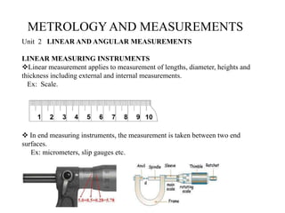
  • 1. METROLOGYAND MEASUREMENTS Unit 2 LINEAR AND ANGULAR MEASUREMENTS LINEAR MEASURING INSTRUMENTS Linear measurement applies to measurement of lengths, diameter, heights and thickness including external and internal measurements. Ex: Scale.  In end measuring instruments, the measurement is taken between two end surfaces. Ex: micrometers, slip gauges etc.
  • 2. The instruments used for linear measurements can be classified as: 1. Direct measuring instruments 2. Indirect measuring instruments METROLOGY AND MEASUREMENTS
  • 3. METROLOGY AND MEASUREMENTS 1.The Direct measuring instruments are of two types: 1.1 Graduated 1.2 Non Graduated 1.1 The graduated instruments include  rules,  vernier calipers,  vernier height gauges,  vernier depth gauges,  micrometers,  dial indicators etc. 1.2 The non graduated instruments include  calipers,  telescopic gauges,  surface gauges,  straight edges,  wire gauges,  screw pitch gauges,  radius gauges,  thickness gauges,  slip gauges etc.
  • 4. METROLOGY AND MEASUREMENTS They can also be classified as 1. Non precision instruments such as steel rule, calipers etc., 2. Precision measuring instruments such as vernier instruments, micrometers, dial gauges etc. VERNIER CALIPERS The vernier instruments generally used in workshop and engineering metrology have comparatively low accuracy Types of Vernier Calipers According to Indian Standard IS: 3651-1974, there are three types of vernier calipers Type A Type B Type C
  • 5. METROLOGY AND MEASUREMENTS Type A: Vernier has jaws on both sides for external and internal measurements and a blade for depth measurement.
  • 6. METROLOGY AND MEASUREMENTS Type B: It is provided with jaws on one side for external and internal measurements.
  • 7. METROLOGY AND MEASUREMENTS Type C: It has jaws on both sides for making the measurement and for marking operations
  • 8. METROLOGY AND MEASUREMENTS Type C: It has jaws on both sides for making the measurement and for marking operations
  • 9. METROLOGY AND MEASUREMENTS Errors in Calipers The degree of accuracy obtained in measurement greatly depends upon the condition of the jaws of the calipers. At most care must be needed before proceeding for the measurement
  • 10. METROLOGY AND MEASUREMENTS MICROMETERS OR SCREW GAUGE There are two types in it. (i) Outside micrometer — To measure external dimensions. (ii) Inside micrometer — To measure internal dimensions Outside micrometer
  • 11. METROLOGY AND MEASUREMENTS Outside micrometer It consists of two scales, 1. main scale. 2.Thimble scale. While the pitch of barrel screw is 0.5 mm the thimble has graduation of 0.01 mm. The least count of this micrometer is 0.01 mm.
  • 14. METROLOGY AND MEASUREMENTS How to hold the measuring component?
  • 15. METROLOGY AND MEASUREMENTS SLIP GAUGES  These are high carbon steel hardened, ground and lapped rectangular blocks, having cross sectional area 0f 30 mm 10mm. Their opposite faces are flat, parallel and are accurately the stated distance apart
  • 16. WRINGING It is nothing but ,combining the faces of slip gauges one over the other. Due to adhesion property of slip gauges, they will stick together. This is because of very high degree of surface finish of the measuring faces. This process is called as wringing METROLOGY AND MEASUREMENTS
  • 17. Classification of Slip Gauges Slip gauges are classified into various types according to their use as follows: 1) Grade 2 2) Grade 1 3) Grade 0 4) Grade 00 5) Calibration grade. METROLOGY AND MEASUREMENTS
  • 18. 1) Grade 2 It is a workshop grade slip gauges used for setting tools, cutters and checking dimensions roughly. 2) Grade 1 The grade 1 is used for precise work in tool rooms. 3) Grade 0 It is used as inspection grade of slip gauges mainly by inspection department. 4) Grade 00 Grade 00 mainly used in high precision works in the form of error detection in instruments. 5) Calibration grade The actual size of the slip gauge is calibrated on a chart supplied by the manufactures. METROLOGY AND MEASUREMENTS
  • 19. LIMIT GAUGES  A limit gauge is not a measuring gauge. Just , used as inspecting gauge. METROLOGY AND MEASUREMENTS
  • 20. Application  The limit gauges are used in inspection .  This gives the information about the products which may be either within the prescribed limit or not.  By using limit gauges report, the control charts of P and C charts are drawn to control invariance of the products.  This procedure is mostly performed by the quality control department of each and every industry.  Limit gauge are mainly used for checking for cylindrical holes of identical components in mass production. METROLOGY AND MEASUREMENTS
  • 21. METROLOGY AND MEASUREMENTS  Purpose of using limit gauges  Components are manufactured as per the specified tolerance limits, upper limit and lower limit.  The dimension of each component should be within this upper and lower limit  If the dimensions are outside these limits, the components will be rejected.  It is just enough whether the size of the component is within the prescribed limits or not. For this purpose, we can make use of gauges known as limit gauges.
  • 22. Types of Limit gauges 1) Plug gauges. 2) Ring gauges. 3) Snap gauges. 1) Plug gauges. 1.1 Double ended plug gauges 1.2 Progressive type of plug gauges METROLOGY AND MEASUREMENTS
  • 23. 1)Plug gauges.  The ends are hardened and accurately finished by grinding.  One end is the GO end and the other end is NOGO end.  The GO end will be equal to the lower limit size of the hole  The NOGO end will be equal to the upper limit size of the hole.  If the size of the hole is within the limits, the GO end should go inside the hole and NOGO end should not go.  If the GO end and does not go, the hole is under size and also if NOGO end goes, the hole is over size. Hence, the components are rejected in both the cases. METROLOGY AND MEASUREMENTS
  • 24. NOGO End GO End METROLOGY AND MEASUREMENTS 1.1 Double ended plug gauges The GO end and NOGO end are arranged on both the ends of the plug. This type has the advantage of easy handling.
  • 25. METROLOGY AND MEASUREMENTS 1.2 Progressive type of plug gauges Both the GO end and NOGO ends are arranged in the same side of the plug.  Use the plug gauge ends progressively one after the other while checking the hole.  It saves time.  The GO end is made larger than the NOGO end in this plug gauges. GO End NOGO End
  • 26. METROLOGY AND MEASUREMENTS 2) RING GAUGES Ring gauges are mainly used for checking the diameter of shafts having a central hole. The periphery of the ring is knurled to give more grips while handling the gauges. e. The hole of GO ring gauge is made to the upper limit size of the shaft and NOGO for the lower limit. While checking the shaft, the GO ring gauge will pass through the shaft and NOGO will not pass. To identify the NOGO ring gauges easily, a red mark or a small groove cut on its periphery. NOGO Gauge GO Gauge
  • 27. METROLOGY AND MEASUREMENTS 3) SNAP GAUGE Snap gauges are used for checking external dimensions. They are also called as gap gauges. Different types of snap gauges are: 1.Double Ended Snap Gauge 2.Progressive Snap Gauge 3.Adjustable Snap Gauge
  • 28. METROLOGY AND MEASUREMENTS 2.1 Double Ended Snap Gauge  This gauge is having two ends in the form of anvils.  The GO anvil is made to lower limit  The NOGO anvil is made to upper limit of the shaft.  It is also known as solid snap gauges GO anvil NOGO anvil
  • 29. 2. 2 Progressive Snap Gauge  This type of snap gauge is also called caliper gauge.  Mainly used for checking large diameters up to 100mm.  Both GO and NOGO anvils at the same end.  The GO anvil should be at the front  The NOGO anvil at the rear.  So, the diameter of the shaft is checked progressively by these two ends.  This type of gauge is made of horse shoe shaped frame with I section to reduce the weight of the snap gauges. METROLOGY AND MEASUREMENTS GO anvil NOGO anvil
  • 30. METROLOGY AND MEASUREMENTS Adjustable Snap Gauge  It has one fixed anvil and two small adjustable anvils.  The distance between the two anvils is adjusted by adjusting the adjustable anvils by means of setscrews.  This adjustment can be made with the help of slip gauges for specified limits of size.
  • 31. METROLOGY AND MEASUREMENTS Interchangeability: Interchangeability occurs when one part in an assembly can be substituted for a similar part which has been made to the same drawing. Interchangeability is possible only when certain standards are strictly followed. Universal interchangeability It means the parts to be assembled are from two different manufacturing sources. Local interchangeability It means all the parts to be assembled are made in the same manufacturing unit.
  • 32. METROLOGY AND MEASUREMENTS Selective Assembly: In selective assembly, the parts are graded ACCORDING TO THE SIZE and only matched grades of mating parts are assembled. This technique is most suitable, where the CLOSE FIT of two components assembled is required. It provides complete protection against non-conforming assemblies and reduces machining costs as close tolerances can be maintained. For example : Some parts (shafts & holes) are manufactured to a tolerance of 0.01 mm, then an automatic gauge can separate them into ten different groups of 0.001 mm limit for selective assembly of the individual parts. Thus high quality and low cost can be achieved. Application of selective assembly Selective assembly is used in aircraft, automobile industries where tolerances are very narrow and not possible to manufacture at reasonable costs
  • 33. METROLOGY AND MEASUREMENTS INTRODUCTION TO ANGULAR MEASUREMENTS:  For measuring the angle, no absolute standard is required.  The angular measurement is done in degrees, minutes and seconds.  (for example 23° 34’ 56” )  The measurement of angular and circular divisions is an important part of inspection.  Like linear measurement, angular measurements have their own importance.  The basic difference between the linear and angular measurement is that no absolute standard is required for angular measurement.
  • 34. METROLOGY AND MEASUREMENTS There are several methods of measuring angles . 1)LINE STANDARD ANGULAR MEASURING DEVICES 2)END STANDARD ANGULAR MEASURING DEVICES The instruments used in Line Standard 1.1) Protractor and Universal Bevel Protractor, The instruments used in End Standard 2.1)Sine bar,
  • 35. 1.1) Protractor  It is the simplest instrument for measuring angles between two faces.  It consists of two arms and an engraved circular scale.  The two arms can be set along the faces between which the angle is to be measured.  The body of the instrument is extended to form one of the arms, and this is known as the stock.  It is the fixed part of the protractor and should be perfectly straight.  The other arm is in the form of a blade that rotates in a turret mounted on the body.  One of the bodies of the turret carries the divided scale and the other member carries a vernier or index.  The ordinary protractor measures angles only in degrees and used for non-precision works. By using angular vernier scale along with it, precision up to 5min can be achieved. METROLOGY AND MEASUREMENTS
  • 36. METROLOGY AND MEASUREMENTS Universal Bevel Protractors Construction  It consists of a base to which a vernier scale is attached.  A protractor dial is mounted on the circular section of the base.  The protractor dial is graduated in degrees with every tenth degree numbered.  The sliding blade is fitted into this dial; it may be extended to either direction and set at any angle to the base.  The blade and the dial are rotated as a unit.  Fine adjustment are obtained with a small knurled headed pinion that, when turned, engages with a gear attached to the blade mount.  The protractor dial may be locked in any position by means of the dial clamp nut. Application  For checking ‘V’ block
  • 37. SINE BAR Sine bars are always used along with slip gauges as a device for the measurement of angles very precisely. They are used to 1) Measure angles very accurately. 2) Locate the work piece to a given angle with very high precision. METROLOGY AND MEASUREMENTS
  • 38. SINE BAR MATERIAL  Sine bars are made from high carbon, high chromium, and corrosion resistant steel.  These materials are highly hardened, ground and stabilized. CONSTRUCTION  In sine bars, two cylinders of equal diameter are attached at lie ends with its axes are mutually parallel to each other.  They are also at equal distance from the upper surface of the sine bar mostly the distance between the axes of two cylinders is 100mm, 200mm or 300mm.  The working surfaces of the rollers are finished to 0.2μm Ra value.  The cylindrical holes are provided to reduce the weight of the sine bar. METROLOGY AND MEASUREMENTS
  • 39. WORKING OF SINE BAR  The operation of a sine bar is based on known TRIGONOMETRIC RELATIONSHIP between the sides and the angle of a right angle triangle.  To measure the angle of a given specimen, one roller of the sine bar is placed on the surface plate and another one roller is placed over the surface of slip gauges.  Now, ‘h be the height of the slip gauges and ‘L’ be the distance between roller centers, then the angle is calculated as Sin α = 𝐻 𝐿 METROLOGY AND MEASUREMENTS
  • 40.  Then the sine bar is set at angle of 0 and clamped on the angle plate.  Now, the work is placed on the sine bar and the dial indicator set at one end of the work is moved across the work piece and deviation is noted.  Slip gauges are adjusted, so that THE DIAL INDICATOR READS ZERO throughout the work surface. METROLOGY AND MEASUREMENTS
  • 41. LIMITATIONS OF SINE BARS 1) Sine bars are fairly reliable for angles than 15°. 2) It is physically difficult to hold in position. 3) Slight errors in sine bar cause larger angular errors. 4) The size of parts to be inspected by sine bar is limited. SOURCES OF ERROR IN SINE BARS 1) Error in distance between roller centers. 2) Error in slip gauge combination. 3) Error in checking of parallelism. 4) Error in parallelism of roller axes with each other. 5) Error in flatness of the upper surface of sine bar. METROLOGY AND MEASUREMENTS
  • 42. AUTO- COLLIMATOR  Auto-collimator is an optical instrument used for the measurement of small angular differences, changes or deflection, plane surface inspection etc.  For small angular measurements, autocollimator provides a very sensitive and accurate approach. METROLOGY AND MEASUREMENTS
  • 44. Basic principle  If a light source is placed in the flows of a collimating lens, it is projected as a parallel beam of light.  If this beam is made to strike a plane reflector, kept normal to the optical axis,  It is reflected back along its own path and is brought to the same focus.  The reflector is tilted through a small angle ‘ɵ’.  Then the parallel beam is deflected twice the angle and is brought to focus in the same plane as the light source. METROLOGY AND MEASUREMENTS