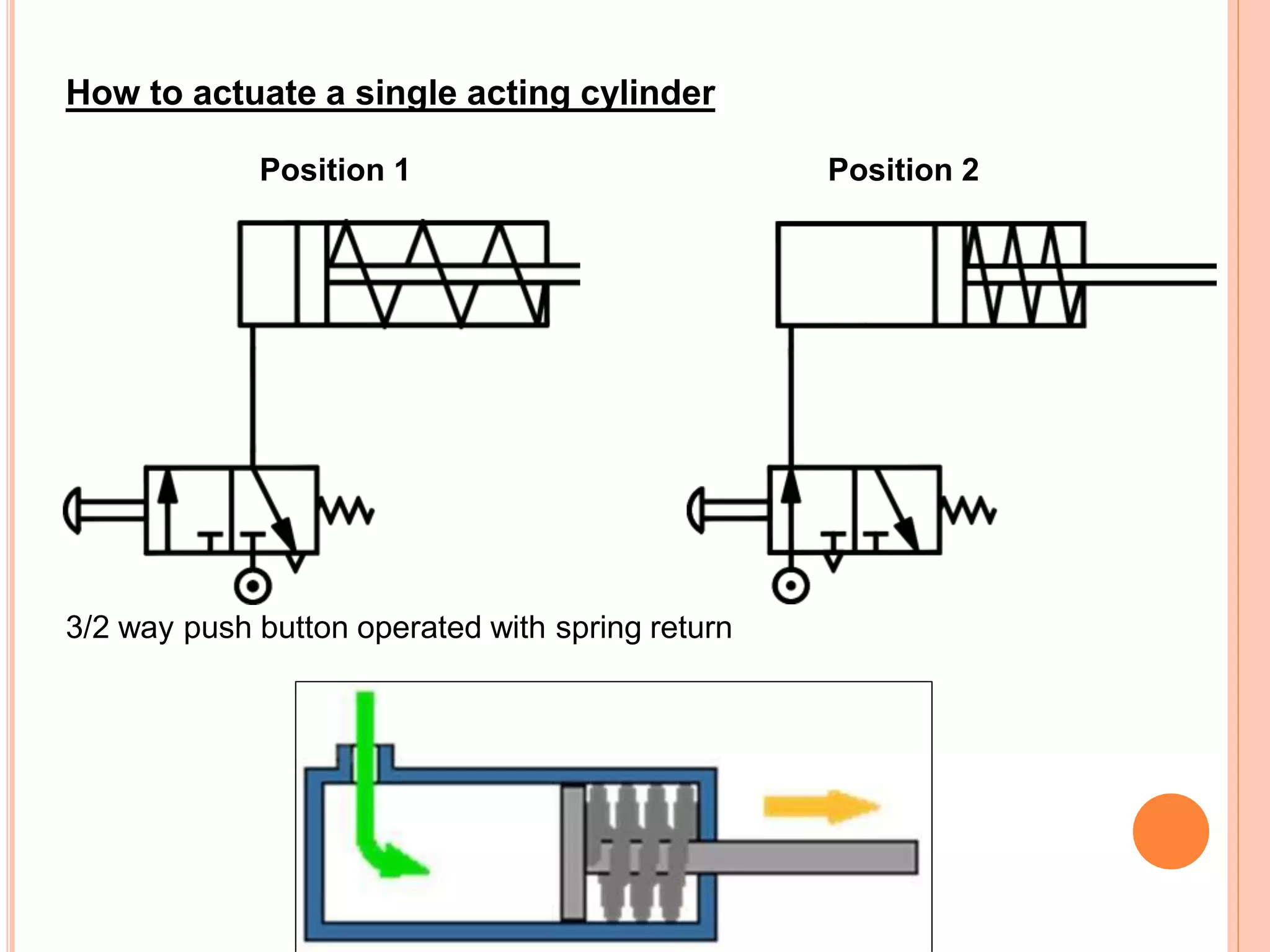
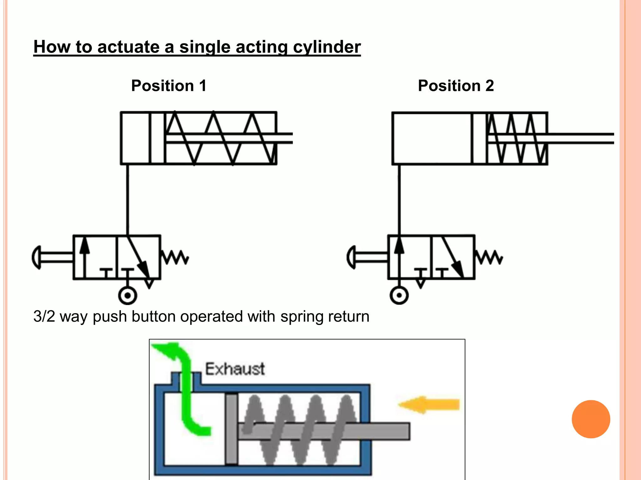
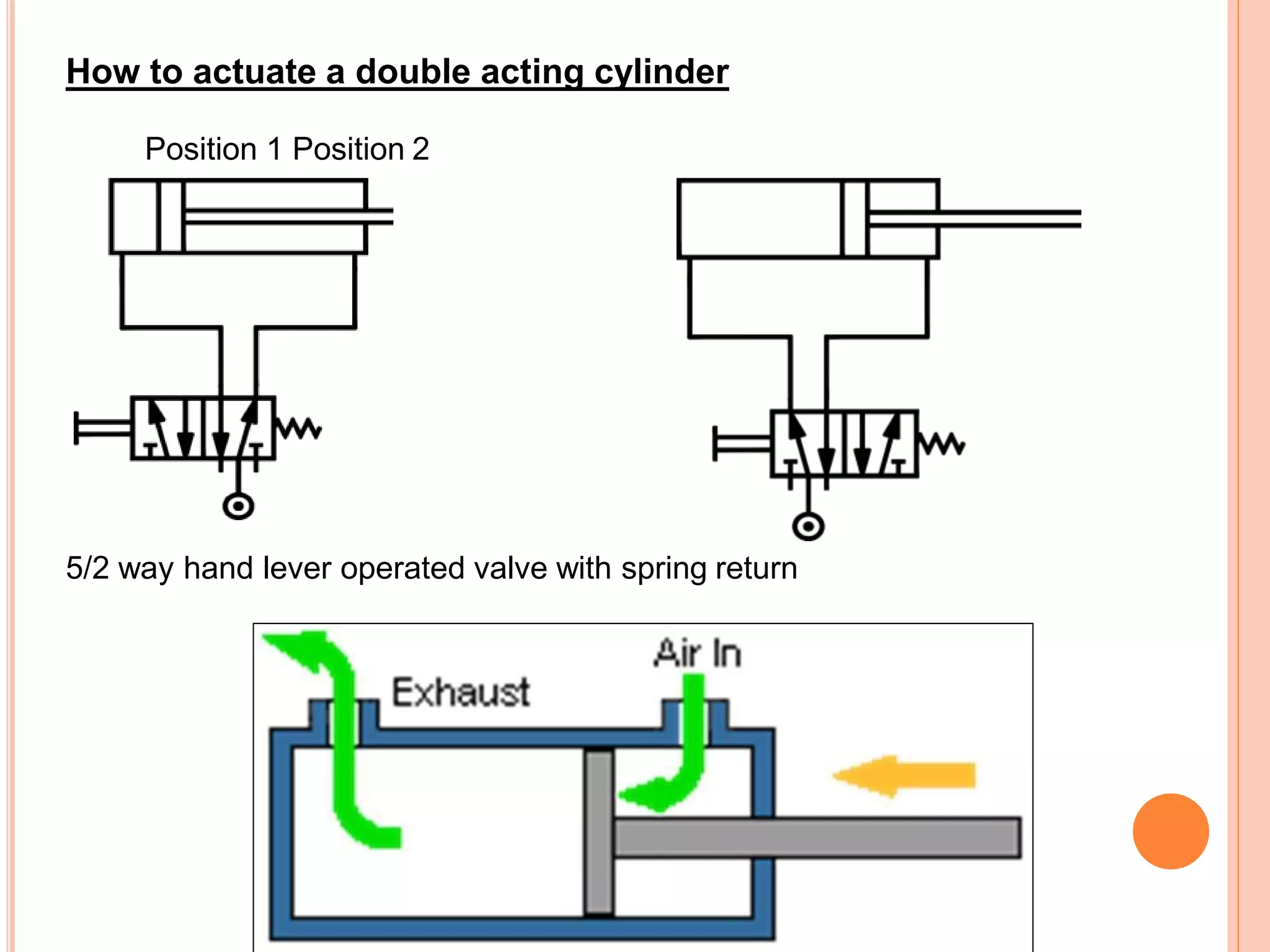
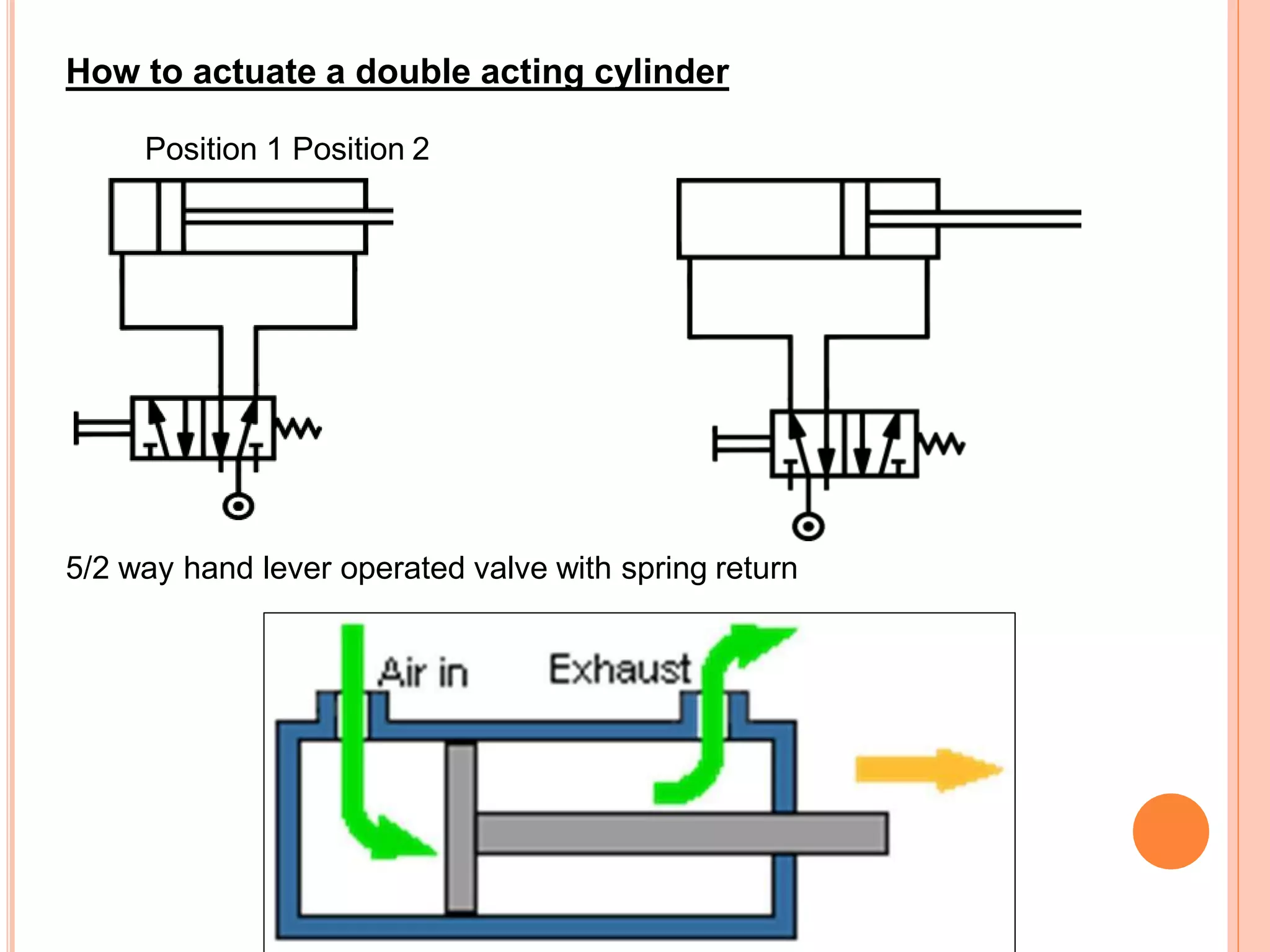
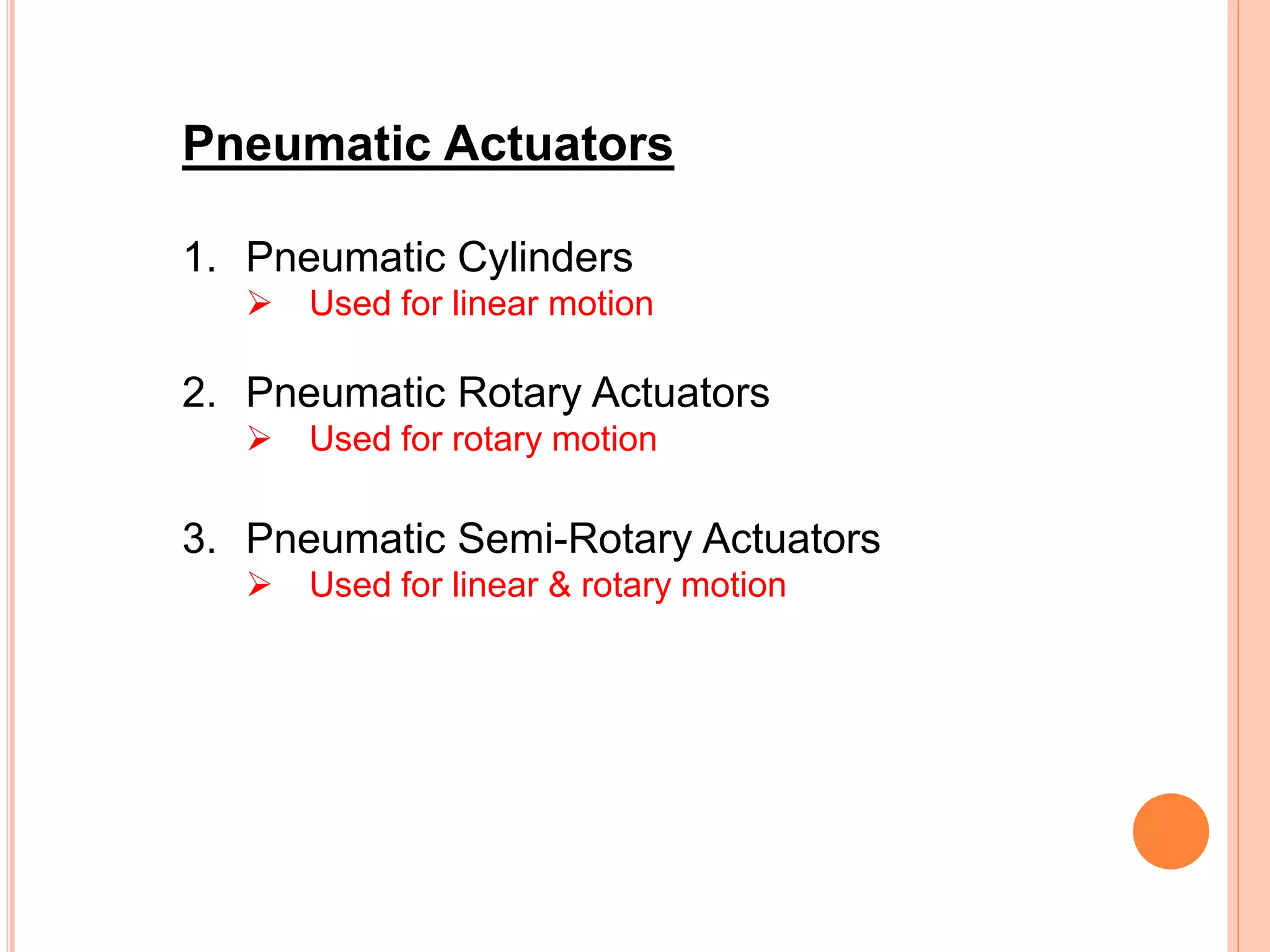
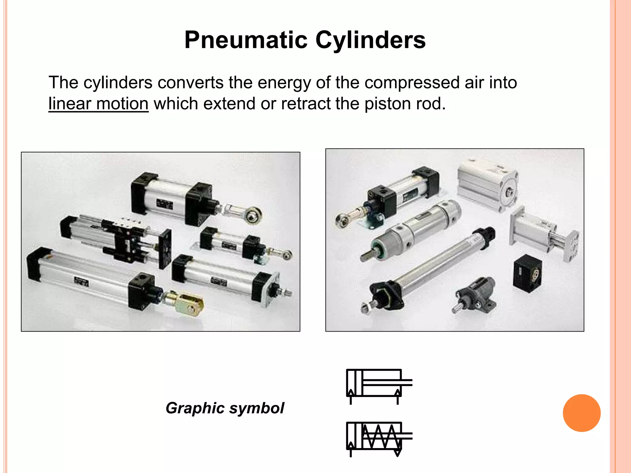
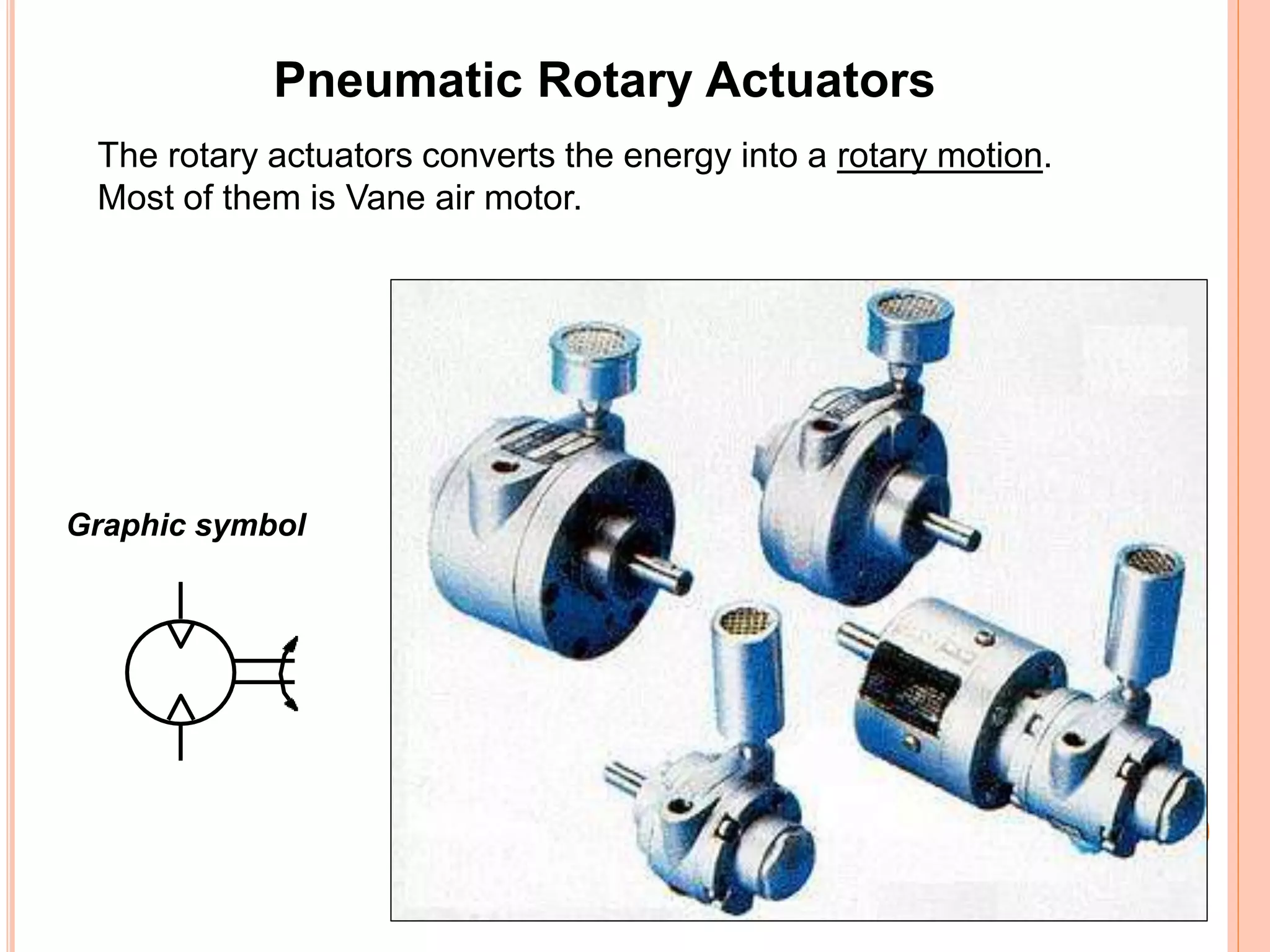
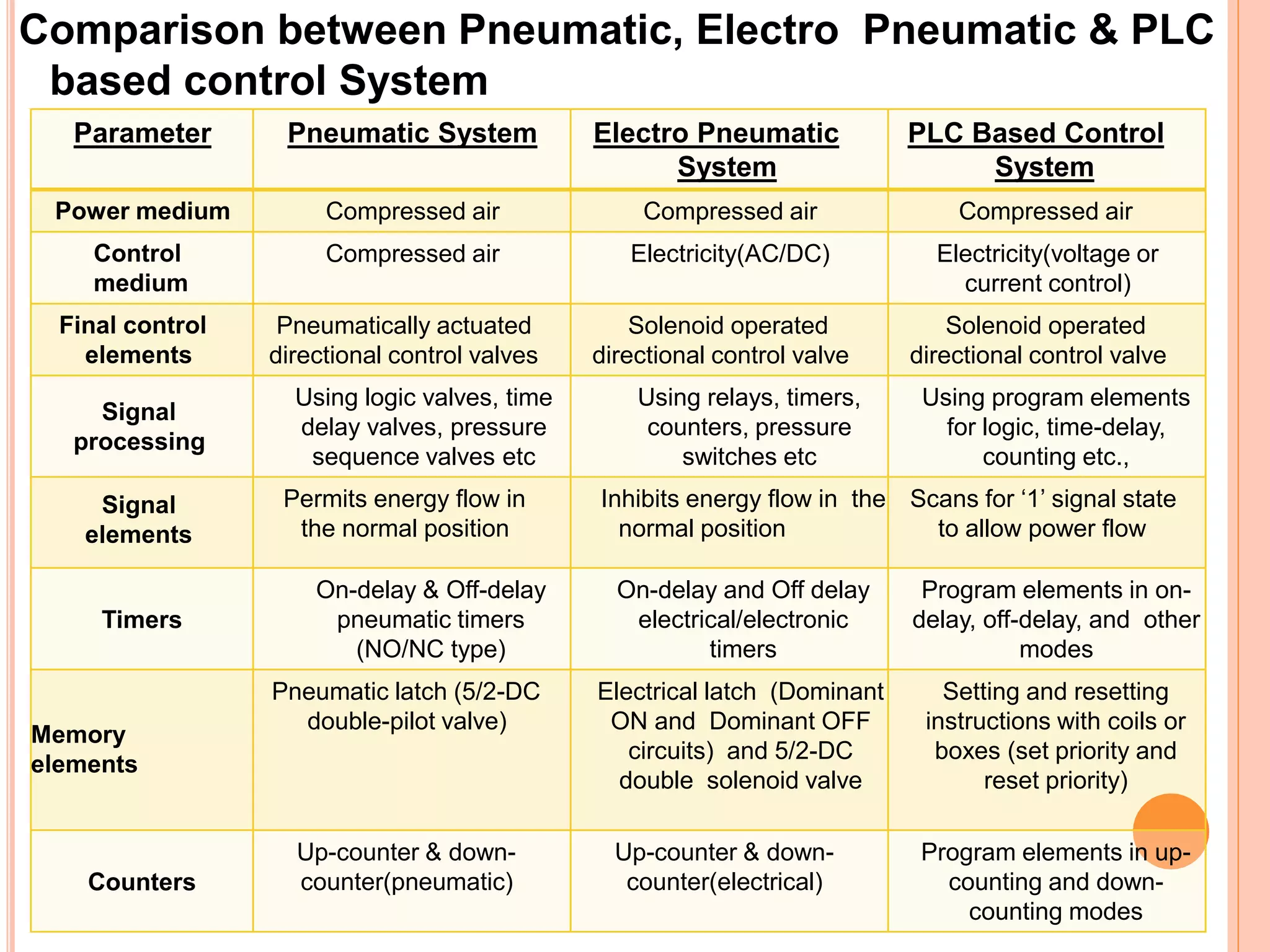
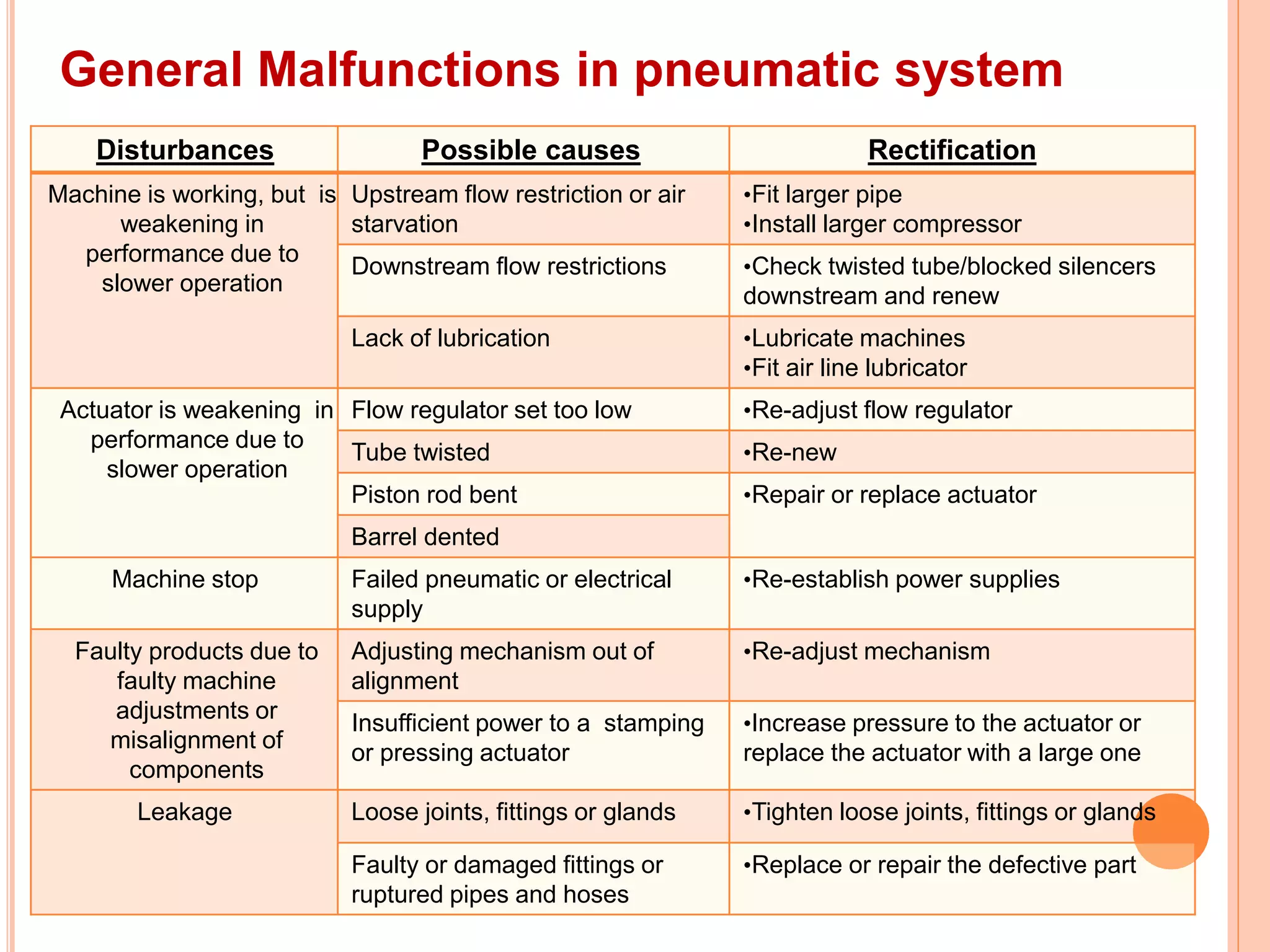
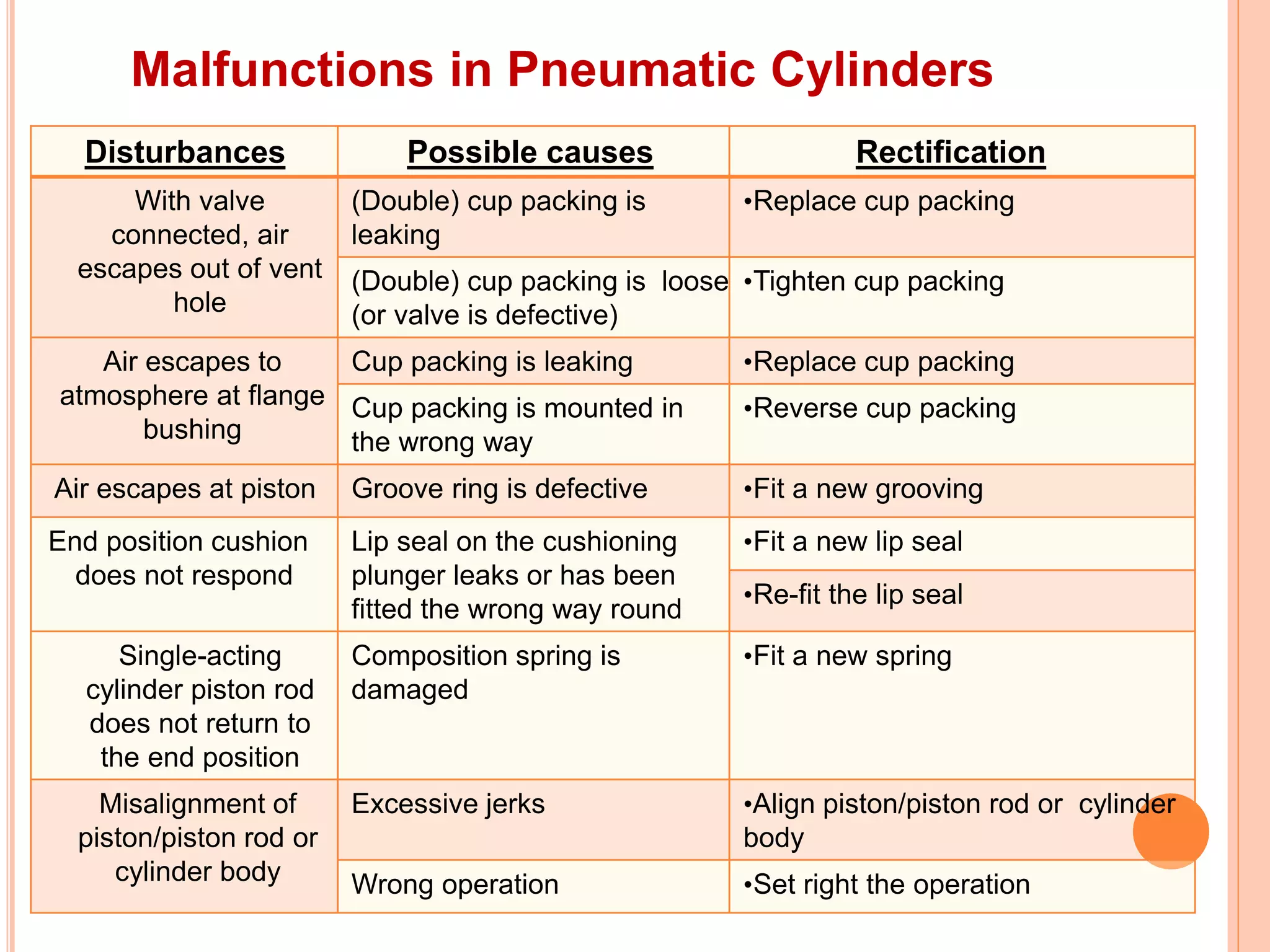
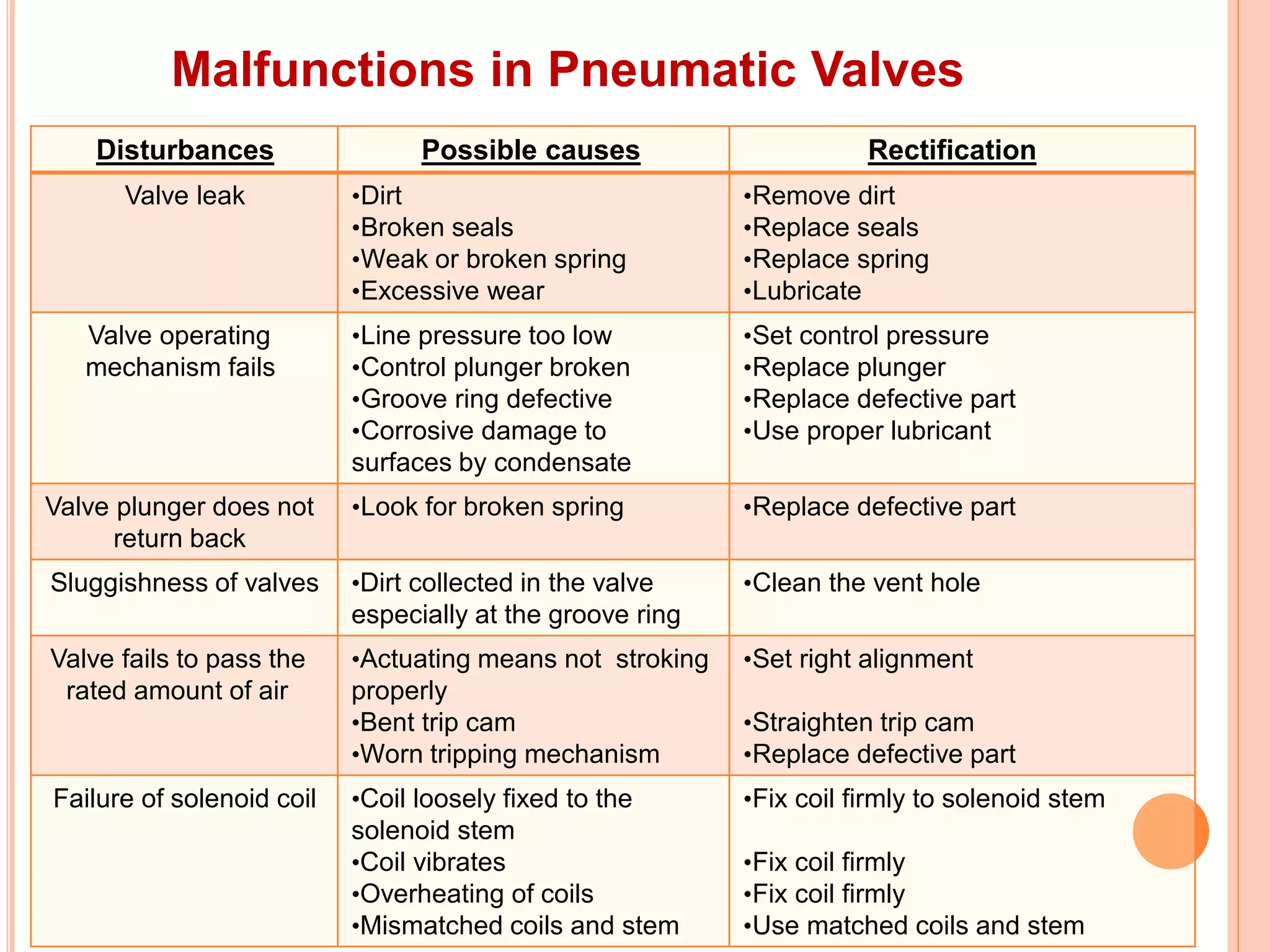
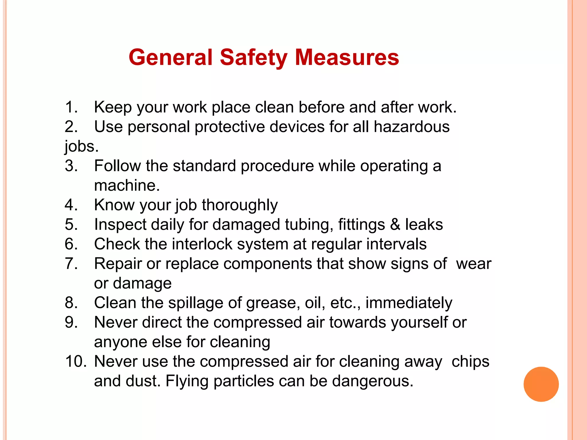
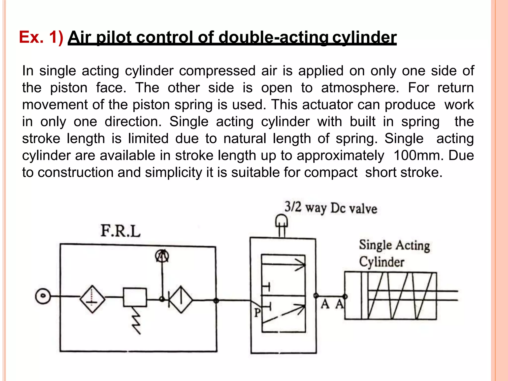
5) WORKING ELEMENTS
How to actuate a single acting cylinder
Position 1 Position 2
3/2 way push button operated with spring return
How to actuate a single acting cylinder
Position 1 Position 2
3/2 way push button operated with spring return
How to actuate a double acting cylinder
Position 1 Position 2
5/2 way hand lever operated valve with spring return
How to actuate a double acting cylinder
Position 1 Position 2
5/2 way hand lever operated valve with spring return
Pneumatic Actuators
1. Pneumatic Cylinders
 Used for linear motion
2. Pneumatic Rotary Actuators
 Used for rotary motion
3. Pneumatic Semi-Rotary Actuators
 Used for linear & rotary motion
Pneumatic Cylinders
The cylinders converts the energy of the compressed air into
linear motion which extend or retract the piston rod.
Graphic symbol
Pneumatic Rotary Actuators
The rotary actuators converts the energy into a rotary motion.
Most of them is Vane air motor.
Graphic symbol
Pneumatic Semi-Rotary Actuators
Limited rotary motion can be achieved by incorporating a rack and
pinion into a linear actuator or as seen opposite by a Vane Mechanism
within the body of the cylinder.
Graphic symbol
Solenoid Valve
Graphic symbol
Direct-Acting Solenoid Valve Animation.mp4
1. Apply Current
2. Magnetic Field Builds
3. Plunger Become Attracting Magnets
4. Magnetic Force Drives Plunger
Working principle of Solenoid Valve
When an electric current flow through a coil, a magnetic field is
generated
The following applies to the strength of the magnetic field.
• Increasing the numbers of windings
increases the field.
• Increasing the strength of
the current increase the field.
• Lengthening the coil reduces
the field.
TYPES OF SOLENOIDS
1) Push 2) Pull 3) Clapper
4) Rotary 5) Open 6) Closed
Comparison between Pneumatic, Electro Pneumatic & PLC
based control System
Parameter Pneumatic System Electro Pneumatic
System
PLC Based Control
System
Power medium Compressed air Compressed air Compressed air
Control
medium
Compressed air Electricity(AC/DC) Electricity(voltage or
current control)
Final control
elements
Pneumatically actuated
directional control valves
Solenoid operated
directional control valve
Solenoid operated
directional control valve
Signal
processing
Using logic valves, time
delay valves, pressure
sequence valves etc
Using relays, timers,
counters, pressure
switches etc
Using program elements
for logic, time-delay,
counting etc.,
Signal
elements
Permits energy flow in
the normal position
Inhibits energy flow in the
normal position
Scans for ‘1’ signal state
to allow power flow
Timers
On-delay & Off-delay
pneumatic timers
(NO/NC type)
On-delay and Off delay
electrical/electronic
timers
Program elements in on-
delay, off-delay, and other
modes
Memory
elements
Pneumatic latch (5/2-DC
double-pilot valve)
Electrical latch (Dominant
ON and Dominant OFF
circuits) and 5/2-DC
double solenoid valve
Setting and resetting
instructions with coils or
boxes (set priority and
reset priority)
Counters
Up-counter & down-
counter(pneumatic)
Up-counter & down-
counter(electrical)
Program elements in up-
counting and down-
counting modes
Air pressure losses in pipelines
General Malfunctions in pneumatic system
Disturbances Possible causes Rectification
Machine is working, but is
weakening in
performance due to
slower operation
Upstream flow restriction or air
starvation
•Fit larger pipe
•Install larger compressor
Downstream flow restrictions •Check twisted tube/blocked silencers
downstream and renew
Lack of lubrication •Lubricate machines
•Fit air line lubricator
Actuator is weakening in
performance due to
slower operation
Flow regulator set too low •Re-adjust flow regulator
Tube twisted •Re-new
Piston rod bent •Repair or replace actuator
Barrel dented
Machine stop Failed pneumatic or electrical
supply
•Re-establish power supplies
Faulty products due to
faulty machine
adjustments or
misalignment of
components
Adjusting mechanism out of
alignment
•Re-adjust mechanism
Insufficient power to a stamping
or pressing actuator
•Increase pressure to the actuator or
replace the actuator with a large one
Leakage Loose joints, fittings or glands •Tighten loose joints, fittings or glands
Faulty or damaged fittings or
ruptured pipes and hoses
•Replace or repair the defective part
Malfunctions in Pneumatic Cylinders
Disturbances Possible causes Rectification
With valve
connected, air
escapes out of vent
hole
(Double) cup packing is
leaking
•Replace cup packing
(Double) cup packing is loose
(or valve is defective)
•Tighten cup packing
Air escapes to
atmosphere at flange
bushing
Cup packing is leaking •Replace cup packing
Cup packing is mounted in
the wrong way
•Reverse cup packing
Air escapes at piston Groove ring is defective •Fit a new grooving
End position cushion
does not respond
Lip seal on the cushioning
plunger leaks or has been
fitted the wrong way round
•Fit a new lip seal
•Re-fit the lip seal
Single-acting
cylinder piston rod
does not return to
the end position
Composition spring is
damaged
•Fit a new spring
Misalignment of
piston/piston rod or
cylinder body
Excessive jerks •Align piston/piston rod or cylinder
body
Wrong operation •Set right the operation
Malfunctions in Pneumatic Valves
Disturbances Possible causes Rectification
Valve leak •Dirt
•Broken seals
•Weak or broken spring
•Excessive wear
•Remove dirt
•Replace seals
•Replace spring
•Lubricate
Valve operating
mechanism fails
•Line pressure too low
•Control plunger broken
•Groove ring defective
•Corrosive damage to
surfaces by condensate
•Set control pressure
•Replace plunger
•Replace defective part
•Use proper lubricant
Valve plunger does not
return back
•Look for broken spring •Replace defective part
Sluggishness of valves •Dirt collected in the valve
especially at the groove ring
•Clean the vent hole
Valve fails to pass the
rated amount of air
•Actuating means not stroking
properly
•Bent trip cam
•Worn tripping mechanism
•Set right alignment
•Straighten trip cam
•Replace defective part
Failure of solenoid coil •Coil loosely fixed to the
solenoid stem
•Coil vibrates
•Overheating of coils
•Mismatched coils and stem
•Fix coil firmly to solenoid stem
•Fix coil firmly
•Fix coil firmly
•Use matched coils and stem
General Safety Measures
1. Keep your work place clean before and after work.
2. Use personal protective devices for all hazardous
jobs.
3. Follow the standard procedure while operating a
machine.
4. Know your job thoroughly
5. Inspect daily for damaged tubing, fittings & leaks
6. Check the interlock system at regular intervals
7. Repair or replace components that show signs of wear
or damage
8. Clean the spillage of grease, oil, etc., immediately
9. Never direct the compressed air towards yourself or
anyone else for cleaning
10. Never use the compressed air for cleaning away chips
and dust. Flying particles can be dangerous.
Basics Pneumatic circuits
A pneumatic circuit is usually designed to
implement the desired logics. However, there
are several basics circuits, which can be
integrated into the final circuit.
In single acting cylinder compressed air is applied on only one side of
the piston face. The other side is open to atmosphere. For return
movement of the piston spring is used. This actuator can produce work
in only one direction. Single acting cylinder with built in spring the
stroke length is limited due to natural length of spring. Single acting
cylinder are available in stroke length up to approximately 100mm. Due
to construction and simplicity it is suitable for compact short stroke.
Ex. 1) Air pilot control of double-acting cylinder
Directional control valve are giving path to an air stream. It controls
actuator. The directional control valve is characterized by its number of
controlled connection or ways and by the number of switching position.
5/2 way D.C. valve has got 2 position and 5 ports i. e. 2 exhaust, 2
outputs & 1 input.
The 5/2 way valve is used primarily as a final control element for the
control of double acting cylinder.
Ex. 2) Air pilot control of double-acting cylinder
The 5/3 way valve has five ports and three position. In this valve lines
are closed in the middle position. This enables the piston rod of cylinder
to be stopped in any position over its range of stroke although
intermediate position of the piston rod cannot be located accurately its
symbol is as follows.
Ex. 3) Air pilot control of double-acting cylinder

Working elements of Pneumatic System with Circuits, Safety, Installation

  • 1.
  • 2.
    How to actuatea single acting cylinder Position 1 Position 2 3/2 way push button operated with spring return
  • 3.
    How to actuatea single acting cylinder Position 1 Position 2 3/2 way push button operated with spring return
  • 4.
    How to actuatea double acting cylinder Position 1 Position 2 5/2 way hand lever operated valve with spring return
  • 5.
    How to actuatea double acting cylinder Position 1 Position 2 5/2 way hand lever operated valve with spring return
  • 6.
    Pneumatic Actuators 1. PneumaticCylinders  Used for linear motion 2. Pneumatic Rotary Actuators  Used for rotary motion 3. Pneumatic Semi-Rotary Actuators  Used for linear & rotary motion
  • 7.
    Pneumatic Cylinders The cylindersconverts the energy of the compressed air into linear motion which extend or retract the piston rod. Graphic symbol
  • 8.
    Pneumatic Rotary Actuators Therotary actuators converts the energy into a rotary motion. Most of them is Vane air motor. Graphic symbol
  • 9.
    Pneumatic Semi-Rotary Actuators Limitedrotary motion can be achieved by incorporating a rack and pinion into a linear actuator or as seen opposite by a Vane Mechanism within the body of the cylinder. Graphic symbol
  • 10.
    Solenoid Valve Graphic symbol Direct-ActingSolenoid Valve Animation.mp4 1. Apply Current 2. Magnetic Field Builds 3. Plunger Become Attracting Magnets 4. Magnetic Force Drives Plunger
  • 11.
    Working principle ofSolenoid Valve When an electric current flow through a coil, a magnetic field is generated The following applies to the strength of the magnetic field. • Increasing the numbers of windings increases the field. • Increasing the strength of the current increase the field. • Lengthening the coil reduces the field.
  • 12.
    TYPES OF SOLENOIDS 1)Push 2) Pull 3) Clapper 4) Rotary 5) Open 6) Closed
  • 13.
    Comparison between Pneumatic,Electro Pneumatic & PLC based control System Parameter Pneumatic System Electro Pneumatic System PLC Based Control System Power medium Compressed air Compressed air Compressed air Control medium Compressed air Electricity(AC/DC) Electricity(voltage or current control) Final control elements Pneumatically actuated directional control valves Solenoid operated directional control valve Solenoid operated directional control valve Signal processing Using logic valves, time delay valves, pressure sequence valves etc Using relays, timers, counters, pressure switches etc Using program elements for logic, time-delay, counting etc., Signal elements Permits energy flow in the normal position Inhibits energy flow in the normal position Scans for ‘1’ signal state to allow power flow Timers On-delay & Off-delay pneumatic timers (NO/NC type) On-delay and Off delay electrical/electronic timers Program elements in on- delay, off-delay, and other modes Memory elements Pneumatic latch (5/2-DC double-pilot valve) Electrical latch (Dominant ON and Dominant OFF circuits) and 5/2-DC double solenoid valve Setting and resetting instructions with coils or boxes (set priority and reset priority) Counters Up-counter & down- counter(pneumatic) Up-counter & down- counter(electrical) Program elements in up- counting and down- counting modes
  • 14.
    Air pressure lossesin pipelines
  • 15.
    General Malfunctions inpneumatic system Disturbances Possible causes Rectification Machine is working, but is weakening in performance due to slower operation Upstream flow restriction or air starvation •Fit larger pipe •Install larger compressor Downstream flow restrictions •Check twisted tube/blocked silencers downstream and renew Lack of lubrication •Lubricate machines •Fit air line lubricator Actuator is weakening in performance due to slower operation Flow regulator set too low •Re-adjust flow regulator Tube twisted •Re-new Piston rod bent •Repair or replace actuator Barrel dented Machine stop Failed pneumatic or electrical supply •Re-establish power supplies Faulty products due to faulty machine adjustments or misalignment of components Adjusting mechanism out of alignment •Re-adjust mechanism Insufficient power to a stamping or pressing actuator •Increase pressure to the actuator or replace the actuator with a large one Leakage Loose joints, fittings or glands •Tighten loose joints, fittings or glands Faulty or damaged fittings or ruptured pipes and hoses •Replace or repair the defective part
  • 16.
    Malfunctions in PneumaticCylinders Disturbances Possible causes Rectification With valve connected, air escapes out of vent hole (Double) cup packing is leaking •Replace cup packing (Double) cup packing is loose (or valve is defective) •Tighten cup packing Air escapes to atmosphere at flange bushing Cup packing is leaking •Replace cup packing Cup packing is mounted in the wrong way •Reverse cup packing Air escapes at piston Groove ring is defective •Fit a new grooving End position cushion does not respond Lip seal on the cushioning plunger leaks or has been fitted the wrong way round •Fit a new lip seal •Re-fit the lip seal Single-acting cylinder piston rod does not return to the end position Composition spring is damaged •Fit a new spring Misalignment of piston/piston rod or cylinder body Excessive jerks •Align piston/piston rod or cylinder body Wrong operation •Set right the operation
  • 17.
    Malfunctions in PneumaticValves Disturbances Possible causes Rectification Valve leak •Dirt •Broken seals •Weak or broken spring •Excessive wear •Remove dirt •Replace seals •Replace spring •Lubricate Valve operating mechanism fails •Line pressure too low •Control plunger broken •Groove ring defective •Corrosive damage to surfaces by condensate •Set control pressure •Replace plunger •Replace defective part •Use proper lubricant Valve plunger does not return back •Look for broken spring •Replace defective part Sluggishness of valves •Dirt collected in the valve especially at the groove ring •Clean the vent hole Valve fails to pass the rated amount of air •Actuating means not stroking properly •Bent trip cam •Worn tripping mechanism •Set right alignment •Straighten trip cam •Replace defective part Failure of solenoid coil •Coil loosely fixed to the solenoid stem •Coil vibrates •Overheating of coils •Mismatched coils and stem •Fix coil firmly to solenoid stem •Fix coil firmly •Fix coil firmly •Use matched coils and stem
  • 18.
    General Safety Measures 1.Keep your work place clean before and after work. 2. Use personal protective devices for all hazardous jobs. 3. Follow the standard procedure while operating a machine. 4. Know your job thoroughly 5. Inspect daily for damaged tubing, fittings & leaks 6. Check the interlock system at regular intervals 7. Repair or replace components that show signs of wear or damage 8. Clean the spillage of grease, oil, etc., immediately 9. Never direct the compressed air towards yourself or anyone else for cleaning 10. Never use the compressed air for cleaning away chips and dust. Flying particles can be dangerous.
  • 19.
    Basics Pneumatic circuits Apneumatic circuit is usually designed to implement the desired logics. However, there are several basics circuits, which can be integrated into the final circuit.
  • 20.
    In single actingcylinder compressed air is applied on only one side of the piston face. The other side is open to atmosphere. For return movement of the piston spring is used. This actuator can produce work in only one direction. Single acting cylinder with built in spring the stroke length is limited due to natural length of spring. Single acting cylinder are available in stroke length up to approximately 100mm. Due to construction and simplicity it is suitable for compact short stroke. Ex. 1) Air pilot control of double-acting cylinder
  • 21.
    Directional control valveare giving path to an air stream. It controls actuator. The directional control valve is characterized by its number of controlled connection or ways and by the number of switching position. 5/2 way D.C. valve has got 2 position and 5 ports i. e. 2 exhaust, 2 outputs & 1 input. The 5/2 way valve is used primarily as a final control element for the control of double acting cylinder. Ex. 2) Air pilot control of double-acting cylinder
  • 22.
    The 5/3 wayvalve has five ports and three position. In this valve lines are closed in the middle position. This enables the piston rod of cylinder to be stopped in any position over its range of stroke although intermediate position of the piston rod cannot be located accurately its symbol is as follows. Ex. 3) Air pilot control of double-acting cylinder