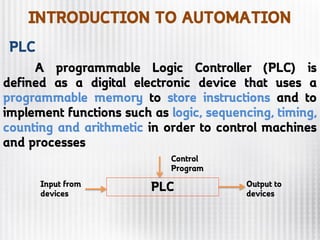
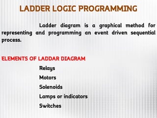
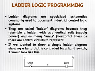
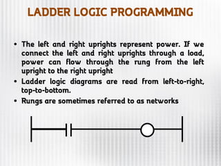
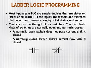
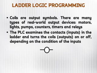
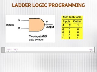
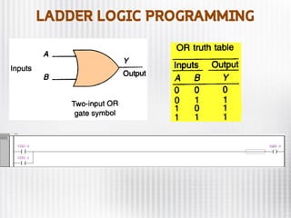
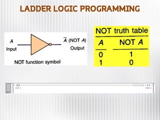
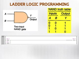
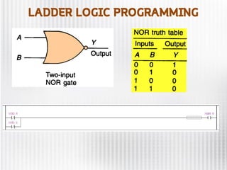
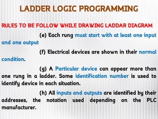
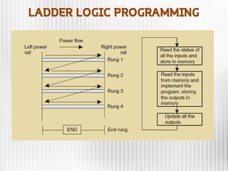
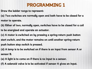
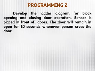
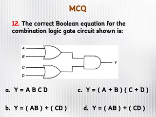
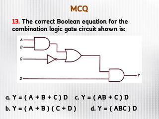
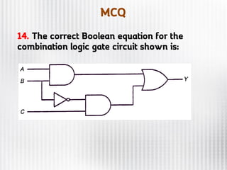
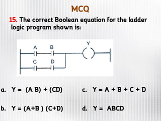
SlideShare a Scribd company logo
1 of 46
Download to read offline
PRESENTED BY
S.VALAI GANESH, AP/MECHANICAL
RAMCO INSTITUTE OF TECHNOLOGY
AGENDA
INTRODUCTION TO AUTOMATION
Automation or automatic control, is the
use of various control systems for operating
equipment such as machinery, processes in
factories, boilers and heat treating ovens,
switching on telephone networks, steering
and stabilization of ships, aircraft and other
applications and vehicles with minimal or
reduced human intervention. Some
processes have been completely automated.
INTRODUCTION TO AUTOMATION
Automation has been achieved by
various means including mechanical,
hydraulic, pneumatic, electrical,
electronic devices and computers,
usually in combination. Complicated
systems, such as modern factories,
airplanes and ships typically use all
these combined techniques.
INTRODUCTION TO AUTOMATION
ADVANTAGES
•Replaces hard physical or monotonous work
•Tasks in hazardous environments, such as
extreme temperatures, or atmospheres that are
radioactive or toxic can be done by machines
•Faster production and cheaper labor costs
•Automation can be maintained with simple quality
checks
•Can perform tasks beyond human capabilities
INTRODUCTION TO AUTOMATION
LIMITATIONS
•As of now, not all tasks can be
automated
•Some tasks are more expensive to
automate
•Initial costs are high
•Failure to maintain a system could result
in the loss of the product
AUTOMATION COMPANIES
INTRODUCTION TO AUTOMATION
EXAMPLE 1 OPENING AND CLOSING DOORS
INTRODUCTION TO AUTOMATION
EXAMPLE 2 ESCALATORS
INTRODUCTION TO AUTOMATION
EXAMPLE 3 TAP OPENING
INTRODUCTION TO AUTOMATION
• PNEUMATICS
• HYDRAULICS
INTRODUCTION TO AUTOMATION
A programmable Logic Controller (PLC) is
defined as a digital electronic device that uses a
programmable memory to store instructions and to
implement functions such as logic, sequencing, timing,
counting and arithmetic in order to control machines
and processes
PLCInput from
devices
Output to
devices
Control
Program
PLC
LADDER LOGIC PROGRAMMING
Ladder diagram is a graphical method for
representing and programming an event driven sequential
process.
ELEMENTS OF LADDAR DIAGRAM
Relays
Motors
Solenoids
Lamps or indicators
Switches
LADDER LOGIC PROGRAMMING
• Ladder diagrams are specialized schematics
commonly used to document industrial control logic
systems.
• They are called "ladder" diagrams because they
resemble a ladder, with two vertical rails (supply
power) and as many "rungs" (horizontal lines) as
there are control circuits to represent.
• If we wanted to draw a simple ladder diagram
showing a lamp that is controlled by a hand switch,
it would look like this:
LADDER LOGIC PROGRAMMING
• The left and right uprights represent power. If we
connect the left and right uprights through a load,
power can flow through the rung from the left
upright to the right upright
• Ladder logic diagrams are read from left-to-right,
top-to-bottom.
• Rungs are sometimes referred to as networks
LADDER LOGIC PROGRAMMING
• Most inputs to a PLC are simple devices that are either on
(true) or off (false). These inputs are sensors and switches
that detect part presence, empty or full status, and so on.
• Contacts can be thought of as switches. The two basic
kinds of switches are normally open and normally closed:
– A normally open switch does not pass current until it
closed
– A normally closed switch allows current flow until it
closed
LADDER LOGIC PROGRAMMING
• Coils are output symbols. There are many
types of real-world output devices: motors,
lights, pumps, counters, timers and relays
• The PLC examines the contacts (inputs) in the
ladder and turns the coils (outputs) on or off,
depending on the condition of the inputs
LADDER LOGIC PROGRAMMING
• Programmable control is based on the basic logic
function (AND, OR, NOT) to form the instruction.
• Parallel contacts are equivalent to an OR gate.
• Series contacts are equivalent to an AND gate.
• Normally-closed contacts are equivalent to a NOT
gate (inverter).
LADDER LOGIC PROGRAMMING
RULES TO BE FOLLOW WHILE DRAWING LADDAR DIAGRAM
(a) The vertical lines of diagram represent the
power rails between which the circuits are connected.
(b) Each rung of ladder defines one operation
in the control process.
(c) The ladder diagram must be read from left
to right and top to bottom.
(d) In RUN mode, PLC goes through entire
ladder program to the end. Then it came back to start position
LADDER LOGIC PROGRAMMING
RULES TO BE FOLLOW WHILE DRAWING LADDAR DIAGRAM
(e) Each rung must start with at least one input
and one output
(f) Electrical devices are shown in their normal
condition.
(g) A Particular device can appear more than
one rung in a ladder. Some identification number is used to
identify device in each situation.
(h) All inputs and outputs are identified by their
addresses, the notation used depending on the PLC
manufacturer.
LADDER LOGIC PROGRAMMING
PROGRAMMING 1
Draw the ladder rungs to represent:
(a) Two switches are normally open and both have to be closed for a
motor to operate.
(b) Either of two, normally open, switches have to be closed for a coil
to be energized and operate an actuator.
(c) A motor is switched on by pressing a spring-return push button
start switch, and the motor remains on until another spring-return
push button stop switch is pressed.
(d) A lamp is to be switched on if there is an input from sensor A or
sensor B.
(e) A light is to come on if there is no input to a sensor.
(f) A solenoid valve is to be activated if sensor A gives an input.
PROGRAMMING 2
Develop the ladder diagram for block
opening and closing door operation. Sensor is
placed in front of doors. The door will remain in
open for 10 seconds whenever person cross the
door.
PROGRAMMING 3
Develop the ladder diagram for bus opening
and closing door operation. When driver press the
button door will open and driver press the same
button for second time door will close.
PROGRAMMING 4
Given two push-to-ON buttons (PB1,PB2),
Red and Green lamps, develop a ladder diagram to
meet the following objectives.
(a) When PB1 is pushed, RED lamp should be ON
and it will continue to be ON till PB2 is pushed
(b) When PB2 is pushed, GREEN lamp should be
ON and it will continue to be ON till PB1 is pushed
(c) If PB1 and PB2 both are pushed
simultaneously, both light should be OFF.
PROGRAMMING 5
Given four normally open switches (P1,P2,S1
and S2) with DC motor (M). Draw a PLC program
to satisfy following objectives:
When P1 is pushed the cycle shall start. The cycle
shall continue to remain ON until P2 is pushed.
When S1 is pushed and S2 is not pushed then
Motor is ON clockwise direction.
When S2 is pushed and S1 is not pushed then
Motor is ON counter clockwise direction.
When P2 is pushed the program stops
MCQ
1. The two binary states can be defined as:
(a) “high” or “low”
(b) “on” or “off”
(c) 1” or “0”
(d) all of these
2. A gate can have one or more
outputs but
only one input. (True/False)
MCQ
3. The ______ table shows the resulting output
for each possible gate input conditions.
a. input status c. data
b. output status d. truth
4. A light that is "off" or a switch that is "open"
would normally be represented by a binary 1.
(True/False)
5. The OR function, implemented using contacts,
requires contacts connected in series. (True/False)
MCQ
6. With an AND gate, if any input is 0, the output
will be 0. (True/False)
7. The symbol shown is that of a(an)
_________ .
(a) AND gate
(b) OR gate
(c) NAND gate
(d) inverter
MCQ
9. The basic rule for an XOR function is that if
one or the other, but not both, inputs are 1 the
output is 1. (True/False)
10. A NAND gate is an AND gate with an inverter
connected to the output. (True/False)
8. Which of the following gates is commonly used
for the comparison of two binary numbers?
(a) NAND
(b) NOR
(c) XOR
(d) NOT
MCQ
11. Which gate logic shown represents the Boolean
equation: ( A + B ) C = Y
(a) (b)
(c) (d)
MCQ
12. The correct Boolean equation for the
combination logic gate circuit shown is:
a. Y = A B C D c. Y = ( A + B ) ( C + D )
b. Y = ( AB ) + ( CD ) d. Y = ( AB ) + ( CD )
MCQ
13. The correct Boolean equation for the
combination logic gate circuit shown is:
a. Y = ( A + B + C ) D c. Y = ( AB + C ) D
b. Y = ( A + B ) ( C + D ) d. Y = ( ABC ) D
MCQ
14. The correct Boolean equation for the
combination logic gate circuit shown is:
MCQ
15. The correct Boolean equation for the ladder
logic program shown is:
a. Y = (A B) + (CD) c. Y = A + B + C + D
b. Y = (A+B ) (C+D) d. Y = ABCD
SOLUTIONS ?
SEE IN NEXT PRESENTATION

More Related Content

What's hot

PLC ARCHITECTURE AND HARDWARE COMPONENTS
PLC ARCHITECTURE AND HARDWARE COMPONENTSPLC ARCHITECTURE AND HARDWARE COMPONENTS
PLC ARCHITECTURE AND HARDWARE COMPONENTSAkshay Dhole
 
PIC18 TIMER PROGRAMMING IN ASSEMBLY AND C
PIC18 TIMER PROGRAMMING IN ASSEMBLY AND CPIC18 TIMER PROGRAMMING IN ASSEMBLY AND C
PIC18 TIMER PROGRAMMING IN ASSEMBLY AND C raosandy11
 
PLC Logic Circuits
PLC Logic CircuitsPLC Logic Circuits
PLC Logic CircuitsAmeen San
 
programmable logic controller presentation
programmable logic controller presentationprogrammable logic controller presentation
programmable logic controller presentationAshutosh Verma
 
TEMPERATURE BASED FAN SPEED CONTROLLER
TEMPERATURE  BASED  FAN  SPEED  CONTROLLERTEMPERATURE  BASED  FAN  SPEED  CONTROLLER
TEMPERATURE BASED FAN SPEED CONTROLLERTarek Erin
 
PLC (PROGRAMMABLE LOGIC CONTROLLER)
PLC (PROGRAMMABLE LOGIC CONTROLLER)PLC (PROGRAMMABLE LOGIC CONTROLLER)
PLC (PROGRAMMABLE LOGIC CONTROLLER)Manoj Gowda K
 
PLC Programming Introduction
PLC Programming IntroductionPLC Programming Introduction
PLC Programming IntroductionPranavAutomation
 
Home Security System using Arduino & GSM
Home Security System using Arduino & GSM Home Security System using Arduino & GSM
Home Security System using Arduino & GSM Aditya Nag
 
TRAFFIC LIGHT CONTROL SYSTEM USING 8085 MICROPROCESSOR
TRAFFIC LIGHT CONTROL SYSTEM USING 8085 MICROPROCESSORTRAFFIC LIGHT CONTROL SYSTEM USING 8085 MICROPROCESSOR
TRAFFIC LIGHT CONTROL SYSTEM USING 8085 MICROPROCESSORSubash Sambath Kumar
 
Pic microcontroller architecture
Pic microcontroller architecturePic microcontroller architecture
Pic microcontroller architectureDominicHendry
 
Introduction to plc (s7)­
Introduction to  plc (s7)­ Introduction to  plc (s7)­
Introduction to plc (s7)­ majitra
 
Silicon controlled rectifier
Silicon controlled rectifierSilicon controlled rectifier
Silicon controlled rectifierRanjith Samala
 

What's hot (20)

PLC ARCHITECTURE AND HARDWARE COMPONENTS
PLC ARCHITECTURE AND HARDWARE COMPONENTSPLC ARCHITECTURE AND HARDWARE COMPONENTS
PLC ARCHITECTURE AND HARDWARE COMPONENTS
 
control circuit
 control circuit control circuit
control circuit
 
PIC18 TIMER PROGRAMMING IN ASSEMBLY AND C
PIC18 TIMER PROGRAMMING IN ASSEMBLY AND CPIC18 TIMER PROGRAMMING IN ASSEMBLY AND C
PIC18 TIMER PROGRAMMING IN ASSEMBLY AND C
 
PLC Logic Circuits
PLC Logic CircuitsPLC Logic Circuits
PLC Logic Circuits
 
Logic gates
Logic gatesLogic gates
Logic gates
 
Plc
PlcPlc
Plc
 
programmable logic controller presentation
programmable logic controller presentationprogrammable logic controller presentation
programmable logic controller presentation
 
Plc basic
Plc basicPlc basic
Plc basic
 
TEMPERATURE BASED FAN SPEED CONTROLLER
TEMPERATURE  BASED  FAN  SPEED  CONTROLLERTEMPERATURE  BASED  FAN  SPEED  CONTROLLER
TEMPERATURE BASED FAN SPEED CONTROLLER
 
PLC (PROGRAMMABLE LOGIC CONTROLLER)
PLC (PROGRAMMABLE LOGIC CONTROLLER)PLC (PROGRAMMABLE LOGIC CONTROLLER)
PLC (PROGRAMMABLE LOGIC CONTROLLER)
 
PLC Programming Introduction
PLC Programming IntroductionPLC Programming Introduction
PLC Programming Introduction
 
Basic PLC Ladder Programming
Basic PLC Ladder ProgrammingBasic PLC Ladder Programming
Basic PLC Ladder Programming
 
Silicon control rectifier
Silicon control rectifierSilicon control rectifier
Silicon control rectifier
 
Home Security System using Arduino & GSM
Home Security System using Arduino & GSM Home Security System using Arduino & GSM
Home Security System using Arduino & GSM
 
TRAFFIC LIGHT CONTROL SYSTEM USING 8085 MICROPROCESSOR
TRAFFIC LIGHT CONTROL SYSTEM USING 8085 MICROPROCESSORTRAFFIC LIGHT CONTROL SYSTEM USING 8085 MICROPROCESSOR
TRAFFIC LIGHT CONTROL SYSTEM USING 8085 MICROPROCESSOR
 
plc introduction
plc introductionplc introduction
plc introduction
 
Pic microcontroller architecture
Pic microcontroller architecturePic microcontroller architecture
Pic microcontroller architecture
 
Introduction to plc (s7)­
Introduction to  plc (s7)­ Introduction to  plc (s7)­
Introduction to plc (s7)­
 
Silicon controlled rectifier
Silicon controlled rectifierSilicon controlled rectifier
Silicon controlled rectifier
 
PLC Architecture
PLC ArchitecturePLC Architecture
PLC Architecture
 

Similar to Introduction to automation

Mechatronics Programmable Logic Controllers
Mechatronics  Programmable Logic ControllersMechatronics  Programmable Logic Controllers
Mechatronics Programmable Logic Controllersganeshkumarbemech
 
Plc scada by bhushan kumbhalkar
Plc scada by bhushan kumbhalkarPlc scada by bhushan kumbhalkar
Plc scada by bhushan kumbhalkarBhushan Kumbhalkar
 
MPC of TWT based Transmitter
MPC of TWT based TransmitterMPC of TWT based Transmitter
MPC of TWT based TransmitterAbhishek Sutrave
 
Plc (PROGRAMMABLE LOGIC CONTROLLER)
Plc (PROGRAMMABLE LOGIC CONTROLLER)Plc (PROGRAMMABLE LOGIC CONTROLLER)
Plc (PROGRAMMABLE LOGIC CONTROLLER)Urval Chotalia
 
programmable logical controller(PLC)
programmable logical controller(PLC)programmable logical controller(PLC)
programmable logical controller(PLC)hemadri sharma
 
Programming logic controllers (plc) seminar
Programming  logic controllers (plc) seminarProgramming  logic controllers (plc) seminar
Programming logic controllers (plc) seminarmanish gharte
 
Programmable Logic Controller
Programmable Logic ControllerProgrammable Logic Controller
Programmable Logic ControllerHimshekhar Das
 
Programmable_Logic_Controllers_Introduction_to_PLCs__(Chapter_1)_Lec1.ppt
Programmable_Logic_Controllers_Introduction_to_PLCs__(Chapter_1)_Lec1.pptProgrammable_Logic_Controllers_Introduction_to_PLCs__(Chapter_1)_Lec1.ppt
Programmable_Logic_Controllers_Introduction_to_PLCs__(Chapter_1)_Lec1.pptMUSTAFAHAIDER53
 

Similar to Introduction to automation (20)

Plc
PlcPlc
Plc
 
Automation21
Automation21Automation21
Automation21
 
Mechatronics Programmable Logic Controllers
Mechatronics  Programmable Logic ControllersMechatronics  Programmable Logic Controllers
Mechatronics Programmable Logic Controllers
 
Plc scada by bhushan kumbhalkar
Plc scada by bhushan kumbhalkarPlc scada by bhushan kumbhalkar
Plc scada by bhushan kumbhalkar
 
10617568.ppt
10617568.ppt10617568.ppt
10617568.ppt
 
Unit 4 - PLC.pptx
Unit 4 - PLC.pptxUnit 4 - PLC.pptx
Unit 4 - PLC.pptx
 
Presentaton on Plc & Scada
Presentaton on Plc & ScadaPresentaton on Plc & Scada
Presentaton on Plc & Scada
 
MPC of TWT based Transmitter
MPC of TWT based TransmitterMPC of TWT based Transmitter
MPC of TWT based Transmitter
 
Plc (PROGRAMMABLE LOGIC CONTROLLER)
Plc (PROGRAMMABLE LOGIC CONTROLLER)Plc (PROGRAMMABLE LOGIC CONTROLLER)
Plc (PROGRAMMABLE LOGIC CONTROLLER)
 
programmable logical controller(PLC)
programmable logical controller(PLC)programmable logical controller(PLC)
programmable logical controller(PLC)
 
Basic PLC
Basic PLCBasic PLC
Basic PLC
 
n5acb0f1c011fb.pdf
n5acb0f1c011fb.pdfn5acb0f1c011fb.pdf
n5acb0f1c011fb.pdf
 
Project on PLC (SILO)
Project on PLC (SILO)Project on PLC (SILO)
Project on PLC (SILO)
 
Programming logic controllers (plc) seminar
Programming  logic controllers (plc) seminarProgramming  logic controllers (plc) seminar
Programming logic controllers (plc) seminar
 
82C55 PPI (1).ppt
82C55 PPI (1).ppt82C55 PPI (1).ppt
82C55 PPI (1).ppt
 
Basic plc
Basic plcBasic plc
Basic plc
 
Programmable Logic Controller
Programmable Logic ControllerProgrammable Logic Controller
Programmable Logic Controller
 
Basic plc 1
Basic plc 1Basic plc 1
Basic plc 1
 
PLC.pdf
PLC.pdfPLC.pdf
PLC.pdf
 
Programmable_Logic_Controllers_Introduction_to_PLCs__(Chapter_1)_Lec1.ppt
Programmable_Logic_Controllers_Introduction_to_PLCs__(Chapter_1)_Lec1.pptProgrammable_Logic_Controllers_Introduction_to_PLCs__(Chapter_1)_Lec1.ppt
Programmable_Logic_Controllers_Introduction_to_PLCs__(Chapter_1)_Lec1.ppt
 

Recently uploaded

Online food ordering system project report.pdf
Online food ordering system project report.pdfOnline food ordering system project report.pdf
Online food ordering system project report.pdfKamal Acharya
 
"Lesotho Leaps Forward: A Chronicle of Transformative Developments"
"Lesotho Leaps Forward: A Chronicle of Transformative Developments""Lesotho Leaps Forward: A Chronicle of Transformative Developments"
"Lesotho Leaps Forward: A Chronicle of Transformative Developments"mphochane1998
 
DC MACHINE-Motoring and generation, Armature circuit equation
DC MACHINE-Motoring and generation, Armature circuit equationDC MACHINE-Motoring and generation, Armature circuit equation
DC MACHINE-Motoring and generation, Armature circuit equationBhangaleSonal
 
HAND TOOLS USED AT ELECTRONICS WORK PRESENTED BY KOUSTAV SARKAR
HAND TOOLS USED AT ELECTRONICS WORK PRESENTED BY KOUSTAV SARKARHAND TOOLS USED AT ELECTRONICS WORK PRESENTED BY KOUSTAV SARKAR
HAND TOOLS USED AT ELECTRONICS WORK PRESENTED BY KOUSTAV SARKARKOUSTAV SARKAR
 
Introduction to Data Visualization,Matplotlib.pdf
Introduction to Data Visualization,Matplotlib.pdfIntroduction to Data Visualization,Matplotlib.pdf
Introduction to Data Visualization,Matplotlib.pdfsumitt6_25730773
 
Learn the concepts of Thermodynamics on Magic Marks
Learn the concepts of Thermodynamics on Magic MarksLearn the concepts of Thermodynamics on Magic Marks
Learn the concepts of Thermodynamics on Magic MarksMagic Marks
 
DeepFakes presentation : brief idea of DeepFakes
DeepFakes presentation : brief idea of DeepFakesDeepFakes presentation : brief idea of DeepFakes
DeepFakes presentation : brief idea of DeepFakesMayuraD1
 
💚Trustworthy Call Girls Pune Call Girls Service Just Call 🍑👄6378878445 🍑👄 Top...
💚Trustworthy Call Girls Pune Call Girls Service Just Call 🍑👄6378878445 🍑👄 Top...💚Trustworthy Call Girls Pune Call Girls Service Just Call 🍑👄6378878445 🍑👄 Top...
💚Trustworthy Call Girls Pune Call Girls Service Just Call 🍑👄6378878445 🍑👄 Top...vershagrag
 
Introduction to Serverless with AWS Lambda
Introduction to Serverless with AWS LambdaIntroduction to Serverless with AWS Lambda
Introduction to Serverless with AWS LambdaOmar Fathy
 
Employee leave management system project.
Employee leave management system project.Employee leave management system project.
Employee leave management system project.Kamal Acharya
 
Work-Permit-Receiver-in-Saudi-Aramco.pptx
Work-Permit-Receiver-in-Saudi-Aramco.pptxWork-Permit-Receiver-in-Saudi-Aramco.pptx
Work-Permit-Receiver-in-Saudi-Aramco.pptxJuliansyahHarahap1
 
Hospital management system project report.pdf
Hospital management system project report.pdfHospital management system project report.pdf
Hospital management system project report.pdfKamal Acharya
 
Double Revolving field theory-how the rotor develops torque
Double Revolving field theory-how the rotor develops torqueDouble Revolving field theory-how the rotor develops torque
Double Revolving field theory-how the rotor develops torqueBhangaleSonal
 
457503602-5-Gas-Well-Testing-and-Analysis-pptx.pptx
457503602-5-Gas-Well-Testing-and-Analysis-pptx.pptx457503602-5-Gas-Well-Testing-and-Analysis-pptx.pptx
457503602-5-Gas-Well-Testing-and-Analysis-pptx.pptxrouholahahmadi9876
 
Thermal Engineering Unit - I & II . ppt
Thermal Engineering  Unit - I & II . pptThermal Engineering  Unit - I & II . ppt
Thermal Engineering Unit - I & II . pptDineshKumar4165
 
A CASE STUDY ON CERAMIC INDUSTRY OF BANGLADESH.pptx
A CASE STUDY ON CERAMIC INDUSTRY OF BANGLADESH.pptxA CASE STUDY ON CERAMIC INDUSTRY OF BANGLADESH.pptx
A CASE STUDY ON CERAMIC INDUSTRY OF BANGLADESH.pptxmaisarahman1
 
data_management_and _data_science_cheat_sheet.pdf
data_management_and _data_science_cheat_sheet.pdfdata_management_and _data_science_cheat_sheet.pdf
data_management_and _data_science_cheat_sheet.pdfJiananWang21
 
Unit 4_Part 1 CSE2001 Exception Handling and Function Template and Class Temp...
Unit 4_Part 1 CSE2001 Exception Handling and Function Template and Class Temp...Unit 4_Part 1 CSE2001 Exception Handling and Function Template and Class Temp...
Unit 4_Part 1 CSE2001 Exception Handling and Function Template and Class Temp...drmkjayanthikannan
 
Generative AI or GenAI technology based PPT
Generative AI or GenAI technology based PPTGenerative AI or GenAI technology based PPT
Generative AI or GenAI technology based PPTbhaskargani46
 

Recently uploaded (20)

Online food ordering system project report.pdf
Online food ordering system project report.pdfOnline food ordering system project report.pdf
Online food ordering system project report.pdf
 
"Lesotho Leaps Forward: A Chronicle of Transformative Developments"
"Lesotho Leaps Forward: A Chronicle of Transformative Developments""Lesotho Leaps Forward: A Chronicle of Transformative Developments"
"Lesotho Leaps Forward: A Chronicle of Transformative Developments"
 
DC MACHINE-Motoring and generation, Armature circuit equation
DC MACHINE-Motoring and generation, Armature circuit equationDC MACHINE-Motoring and generation, Armature circuit equation
DC MACHINE-Motoring and generation, Armature circuit equation
 
HAND TOOLS USED AT ELECTRONICS WORK PRESENTED BY KOUSTAV SARKAR
HAND TOOLS USED AT ELECTRONICS WORK PRESENTED BY KOUSTAV SARKARHAND TOOLS USED AT ELECTRONICS WORK PRESENTED BY KOUSTAV SARKAR
HAND TOOLS USED AT ELECTRONICS WORK PRESENTED BY KOUSTAV SARKAR
 
Introduction to Data Visualization,Matplotlib.pdf
Introduction to Data Visualization,Matplotlib.pdfIntroduction to Data Visualization,Matplotlib.pdf
Introduction to Data Visualization,Matplotlib.pdf
 
Learn the concepts of Thermodynamics on Magic Marks
Learn the concepts of Thermodynamics on Magic MarksLearn the concepts of Thermodynamics on Magic Marks
Learn the concepts of Thermodynamics on Magic Marks
 
DeepFakes presentation : brief idea of DeepFakes
DeepFakes presentation : brief idea of DeepFakesDeepFakes presentation : brief idea of DeepFakes
DeepFakes presentation : brief idea of DeepFakes
 
💚Trustworthy Call Girls Pune Call Girls Service Just Call 🍑👄6378878445 🍑👄 Top...
💚Trustworthy Call Girls Pune Call Girls Service Just Call 🍑👄6378878445 🍑👄 Top...💚Trustworthy Call Girls Pune Call Girls Service Just Call 🍑👄6378878445 🍑👄 Top...
💚Trustworthy Call Girls Pune Call Girls Service Just Call 🍑👄6378878445 🍑👄 Top...
 
Introduction to Serverless with AWS Lambda
Introduction to Serverless with AWS LambdaIntroduction to Serverless with AWS Lambda
Introduction to Serverless with AWS Lambda
 
Employee leave management system project.
Employee leave management system project.Employee leave management system project.
Employee leave management system project.
 
Work-Permit-Receiver-in-Saudi-Aramco.pptx
Work-Permit-Receiver-in-Saudi-Aramco.pptxWork-Permit-Receiver-in-Saudi-Aramco.pptx
Work-Permit-Receiver-in-Saudi-Aramco.pptx
 
Hospital management system project report.pdf
Hospital management system project report.pdfHospital management system project report.pdf
Hospital management system project report.pdf
 
Double Revolving field theory-how the rotor develops torque
Double Revolving field theory-how the rotor develops torqueDouble Revolving field theory-how the rotor develops torque
Double Revolving field theory-how the rotor develops torque
 
457503602-5-Gas-Well-Testing-and-Analysis-pptx.pptx
457503602-5-Gas-Well-Testing-and-Analysis-pptx.pptx457503602-5-Gas-Well-Testing-and-Analysis-pptx.pptx
457503602-5-Gas-Well-Testing-and-Analysis-pptx.pptx
 
Thermal Engineering Unit - I & II . ppt
Thermal Engineering  Unit - I & II . pptThermal Engineering  Unit - I & II . ppt
Thermal Engineering Unit - I & II . ppt
 
Cara Menggugurkan Sperma Yang Masuk Rahim Biyar Tidak Hamil
Cara Menggugurkan Sperma Yang Masuk Rahim Biyar Tidak HamilCara Menggugurkan Sperma Yang Masuk Rahim Biyar Tidak Hamil
Cara Menggugurkan Sperma Yang Masuk Rahim Biyar Tidak Hamil
 
A CASE STUDY ON CERAMIC INDUSTRY OF BANGLADESH.pptx
A CASE STUDY ON CERAMIC INDUSTRY OF BANGLADESH.pptxA CASE STUDY ON CERAMIC INDUSTRY OF BANGLADESH.pptx
A CASE STUDY ON CERAMIC INDUSTRY OF BANGLADESH.pptx
 
data_management_and _data_science_cheat_sheet.pdf
data_management_and _data_science_cheat_sheet.pdfdata_management_and _data_science_cheat_sheet.pdf
data_management_and _data_science_cheat_sheet.pdf
 
Unit 4_Part 1 CSE2001 Exception Handling and Function Template and Class Temp...
Unit 4_Part 1 CSE2001 Exception Handling and Function Template and Class Temp...Unit 4_Part 1 CSE2001 Exception Handling and Function Template and Class Temp...
Unit 4_Part 1 CSE2001 Exception Handling and Function Template and Class Temp...
 
Generative AI or GenAI technology based PPT
Generative AI or GenAI technology based PPTGenerative AI or GenAI technology based PPT
Generative AI or GenAI technology based PPT
 

Introduction to automation

  • 1. PRESENTED BY S.VALAI GANESH, AP/MECHANICAL RAMCO INSTITUTE OF TECHNOLOGY
  • 3. INTRODUCTION TO AUTOMATION Automation or automatic control, is the use of various control systems for operating equipment such as machinery, processes in factories, boilers and heat treating ovens, switching on telephone networks, steering and stabilization of ships, aircraft and other applications and vehicles with minimal or reduced human intervention. Some processes have been completely automated.
  • 4. INTRODUCTION TO AUTOMATION Automation has been achieved by various means including mechanical, hydraulic, pneumatic, electrical, electronic devices and computers, usually in combination. Complicated systems, such as modern factories, airplanes and ships typically use all these combined techniques.
  • 5. INTRODUCTION TO AUTOMATION ADVANTAGES •Replaces hard physical or monotonous work •Tasks in hazardous environments, such as extreme temperatures, or atmospheres that are radioactive or toxic can be done by machines •Faster production and cheaper labor costs •Automation can be maintained with simple quality checks •Can perform tasks beyond human capabilities
  • 6. INTRODUCTION TO AUTOMATION LIMITATIONS •As of now, not all tasks can be automated •Some tasks are more expensive to automate •Initial costs are high •Failure to maintain a system could result in the loss of the product
  • 8. INTRODUCTION TO AUTOMATION EXAMPLE 1 OPENING AND CLOSING DOORS
  • 11. INTRODUCTION TO AUTOMATION • PNEUMATICS • HYDRAULICS
  • 12. INTRODUCTION TO AUTOMATION A programmable Logic Controller (PLC) is defined as a digital electronic device that uses a programmable memory to store instructions and to implement functions such as logic, sequencing, timing, counting and arithmetic in order to control machines and processes PLCInput from devices Output to devices Control Program PLC
  • 13. LADDER LOGIC PROGRAMMING Ladder diagram is a graphical method for representing and programming an event driven sequential process. ELEMENTS OF LADDAR DIAGRAM Relays Motors Solenoids Lamps or indicators Switches
  • 14. LADDER LOGIC PROGRAMMING • Ladder diagrams are specialized schematics commonly used to document industrial control logic systems. • They are called "ladder" diagrams because they resemble a ladder, with two vertical rails (supply power) and as many "rungs" (horizontal lines) as there are control circuits to represent. • If we wanted to draw a simple ladder diagram showing a lamp that is controlled by a hand switch, it would look like this:
  • 15. LADDER LOGIC PROGRAMMING • The left and right uprights represent power. If we connect the left and right uprights through a load, power can flow through the rung from the left upright to the right upright • Ladder logic diagrams are read from left-to-right, top-to-bottom. • Rungs are sometimes referred to as networks
  • 16. LADDER LOGIC PROGRAMMING • Most inputs to a PLC are simple devices that are either on (true) or off (false). These inputs are sensors and switches that detect part presence, empty or full status, and so on. • Contacts can be thought of as switches. The two basic kinds of switches are normally open and normally closed: – A normally open switch does not pass current until it closed – A normally closed switch allows current flow until it closed
  • 17. LADDER LOGIC PROGRAMMING • Coils are output symbols. There are many types of real-world output devices: motors, lights, pumps, counters, timers and relays • The PLC examines the contacts (inputs) in the ladder and turns the coils (outputs) on or off, depending on the condition of the inputs
  • 18. LADDER LOGIC PROGRAMMING • Programmable control is based on the basic logic function (AND, OR, NOT) to form the instruction. • Parallel contacts are equivalent to an OR gate. • Series contacts are equivalent to an AND gate. • Normally-closed contacts are equivalent to a NOT gate (inverter).
  • 29. LADDER LOGIC PROGRAMMING RULES TO BE FOLLOW WHILE DRAWING LADDAR DIAGRAM (a) The vertical lines of diagram represent the power rails between which the circuits are connected. (b) Each rung of ladder defines one operation in the control process. (c) The ladder diagram must be read from left to right and top to bottom. (d) In RUN mode, PLC goes through entire ladder program to the end. Then it came back to start position
  • 30. LADDER LOGIC PROGRAMMING RULES TO BE FOLLOW WHILE DRAWING LADDAR DIAGRAM (e) Each rung must start with at least one input and one output (f) Electrical devices are shown in their normal condition. (g) A Particular device can appear more than one rung in a ladder. Some identification number is used to identify device in each situation. (h) All inputs and outputs are identified by their addresses, the notation used depending on the PLC manufacturer.
  • 32. PROGRAMMING 1 Draw the ladder rungs to represent: (a) Two switches are normally open and both have to be closed for a motor to operate. (b) Either of two, normally open, switches have to be closed for a coil to be energized and operate an actuator. (c) A motor is switched on by pressing a spring-return push button start switch, and the motor remains on until another spring-return push button stop switch is pressed. (d) A lamp is to be switched on if there is an input from sensor A or sensor B. (e) A light is to come on if there is no input to a sensor. (f) A solenoid valve is to be activated if sensor A gives an input.
  • 33. PROGRAMMING 2 Develop the ladder diagram for block opening and closing door operation. Sensor is placed in front of doors. The door will remain in open for 10 seconds whenever person cross the door.
  • 34. PROGRAMMING 3 Develop the ladder diagram for bus opening and closing door operation. When driver press the button door will open and driver press the same button for second time door will close.
  • 35. PROGRAMMING 4 Given two push-to-ON buttons (PB1,PB2), Red and Green lamps, develop a ladder diagram to meet the following objectives. (a) When PB1 is pushed, RED lamp should be ON and it will continue to be ON till PB2 is pushed (b) When PB2 is pushed, GREEN lamp should be ON and it will continue to be ON till PB1 is pushed (c) If PB1 and PB2 both are pushed simultaneously, both light should be OFF.
  • 36. PROGRAMMING 5 Given four normally open switches (P1,P2,S1 and S2) with DC motor (M). Draw a PLC program to satisfy following objectives: When P1 is pushed the cycle shall start. The cycle shall continue to remain ON until P2 is pushed. When S1 is pushed and S2 is not pushed then Motor is ON clockwise direction. When S2 is pushed and S1 is not pushed then Motor is ON counter clockwise direction. When P2 is pushed the program stops
  • 37. MCQ 1. The two binary states can be defined as: (a) “high” or “low” (b) “on” or “off” (c) 1” or “0” (d) all of these 2. A gate can have one or more outputs but only one input. (True/False)
  • 38. MCQ 3. The ______ table shows the resulting output for each possible gate input conditions. a. input status c. data b. output status d. truth 4. A light that is "off" or a switch that is "open" would normally be represented by a binary 1. (True/False) 5. The OR function, implemented using contacts, requires contacts connected in series. (True/False)
  • 39. MCQ 6. With an AND gate, if any input is 0, the output will be 0. (True/False) 7. The symbol shown is that of a(an) _________ . (a) AND gate (b) OR gate (c) NAND gate (d) inverter
  • 40. MCQ 9. The basic rule for an XOR function is that if one or the other, but not both, inputs are 1 the output is 1. (True/False) 10. A NAND gate is an AND gate with an inverter connected to the output. (True/False) 8. Which of the following gates is commonly used for the comparison of two binary numbers? (a) NAND (b) NOR (c) XOR (d) NOT
  • 41. MCQ 11. Which gate logic shown represents the Boolean equation: ( A + B ) C = Y (a) (b) (c) (d)
  • 42. MCQ 12. The correct Boolean equation for the combination logic gate circuit shown is: a. Y = A B C D c. Y = ( A + B ) ( C + D ) b. Y = ( AB ) + ( CD ) d. Y = ( AB ) + ( CD )
  • 43. MCQ 13. The correct Boolean equation for the combination logic gate circuit shown is: a. Y = ( A + B + C ) D c. Y = ( AB + C ) D b. Y = ( A + B ) ( C + D ) d. Y = ( ABC ) D
  • 44. MCQ 14. The correct Boolean equation for the combination logic gate circuit shown is:
  • 45. MCQ 15. The correct Boolean equation for the ladder logic program shown is: a. Y = (A B) + (CD) c. Y = A + B + C + D b. Y = (A+B ) (C+D) d. Y = ABCD
  • 46. SOLUTIONS ? SEE IN NEXT PRESENTATION