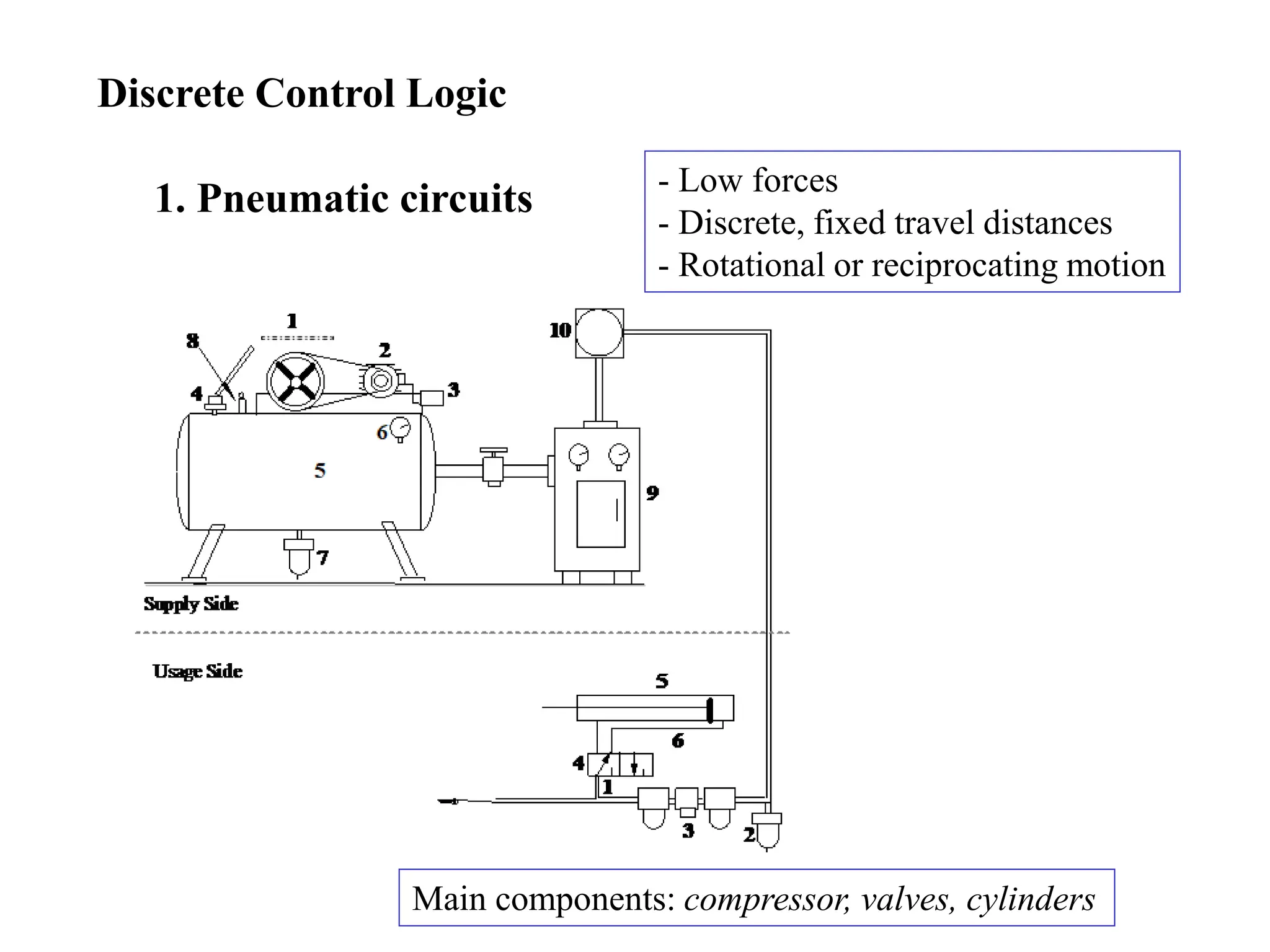
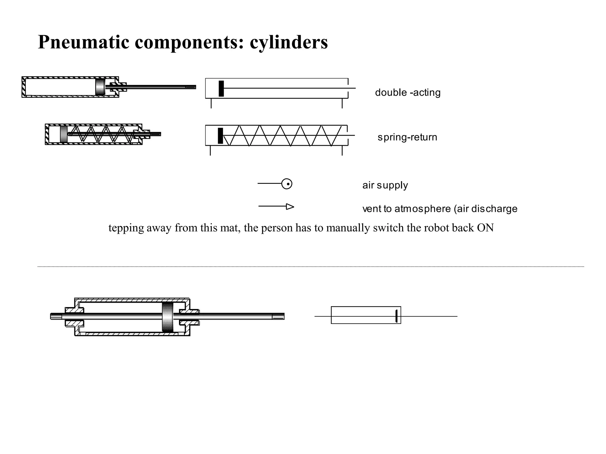
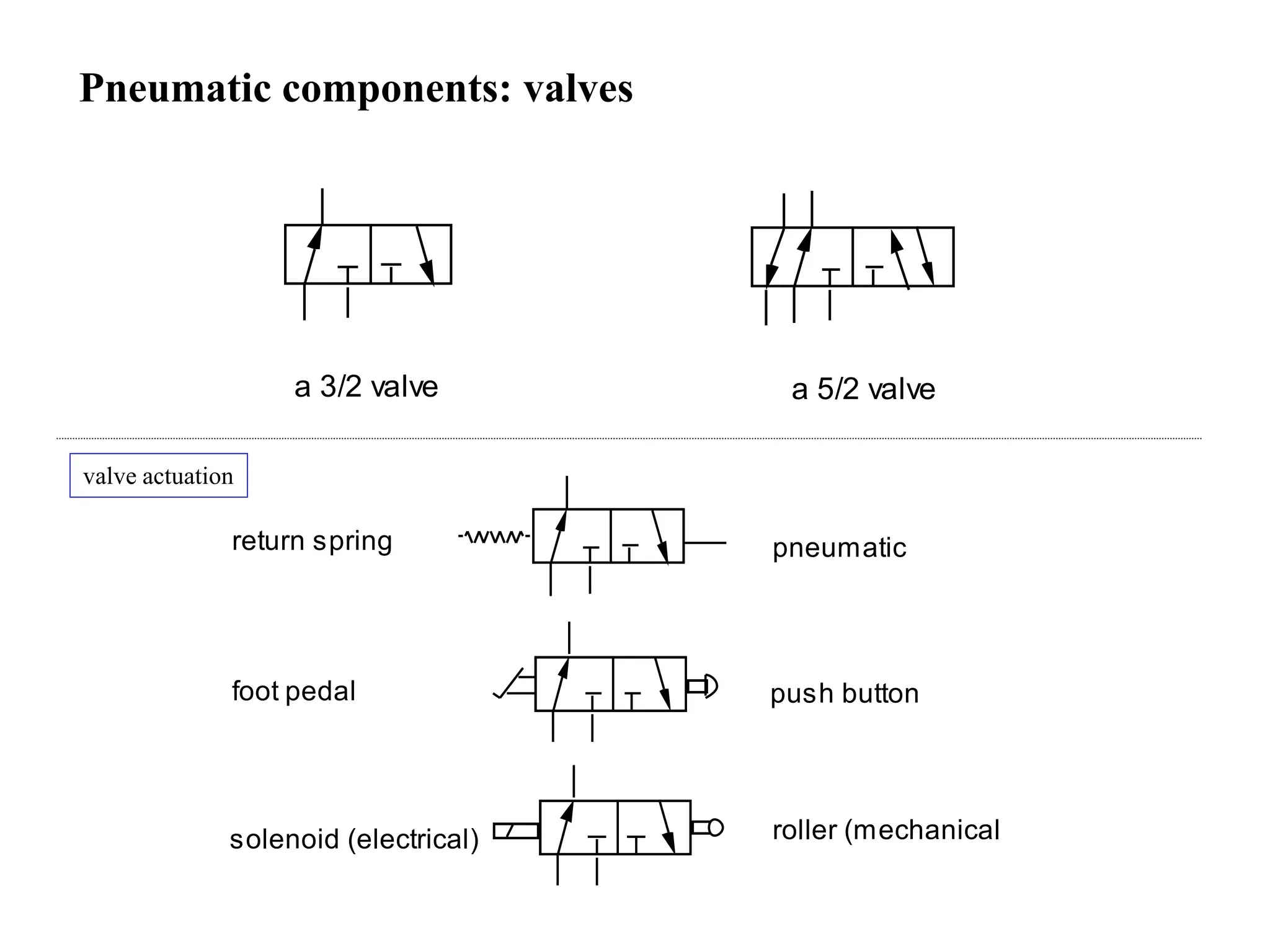
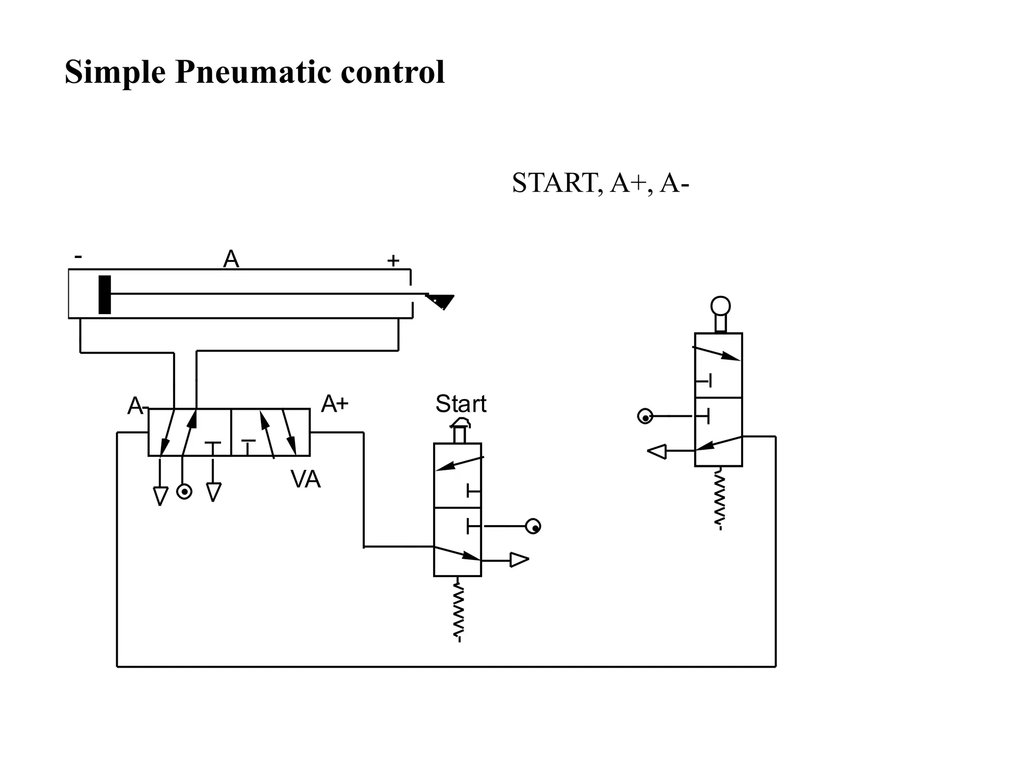
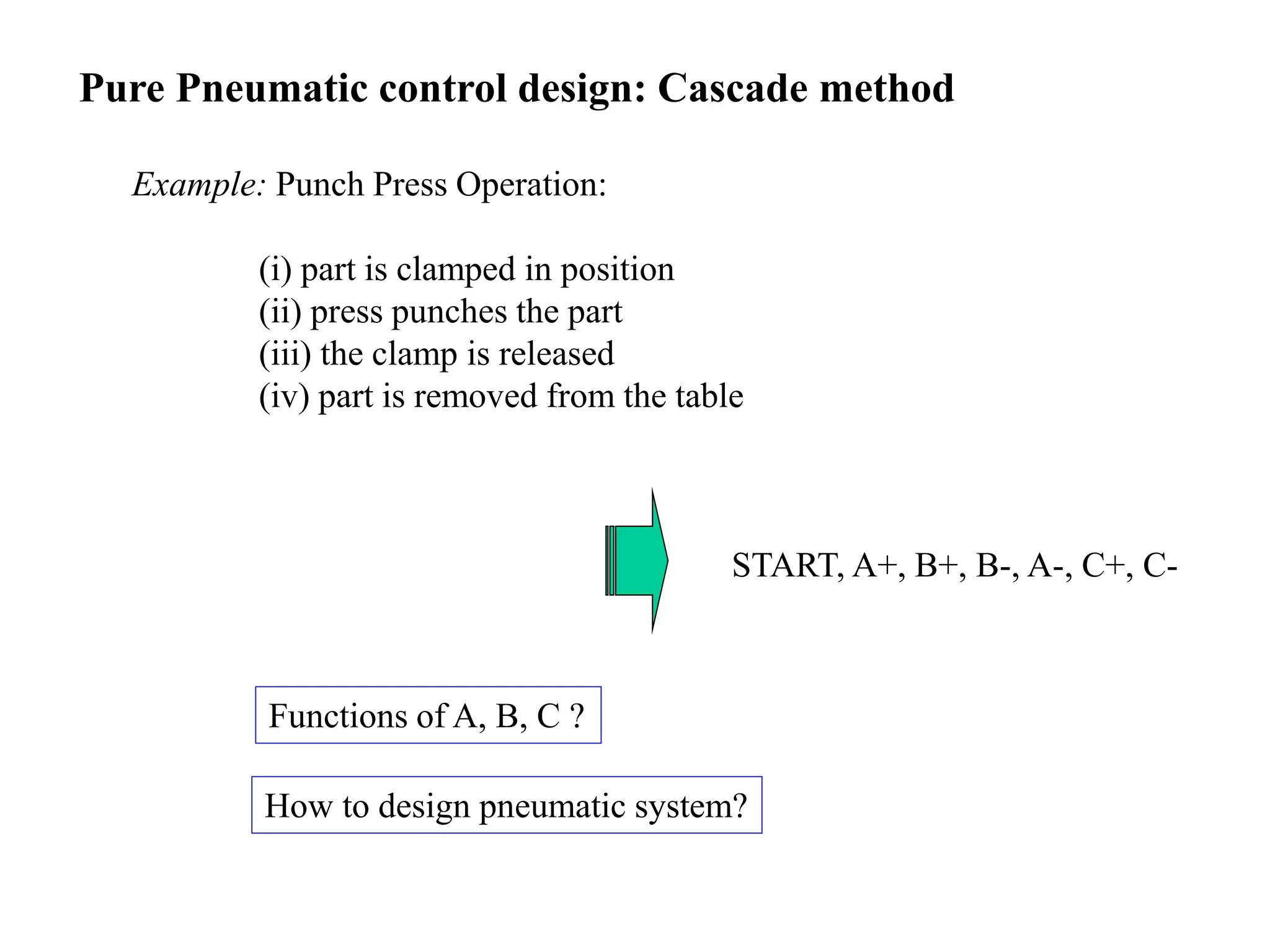
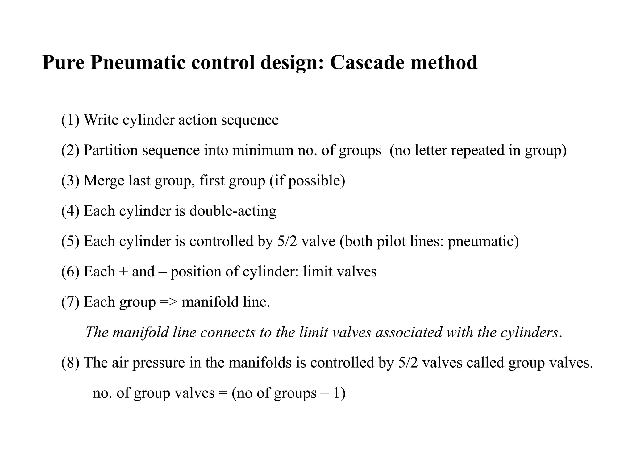
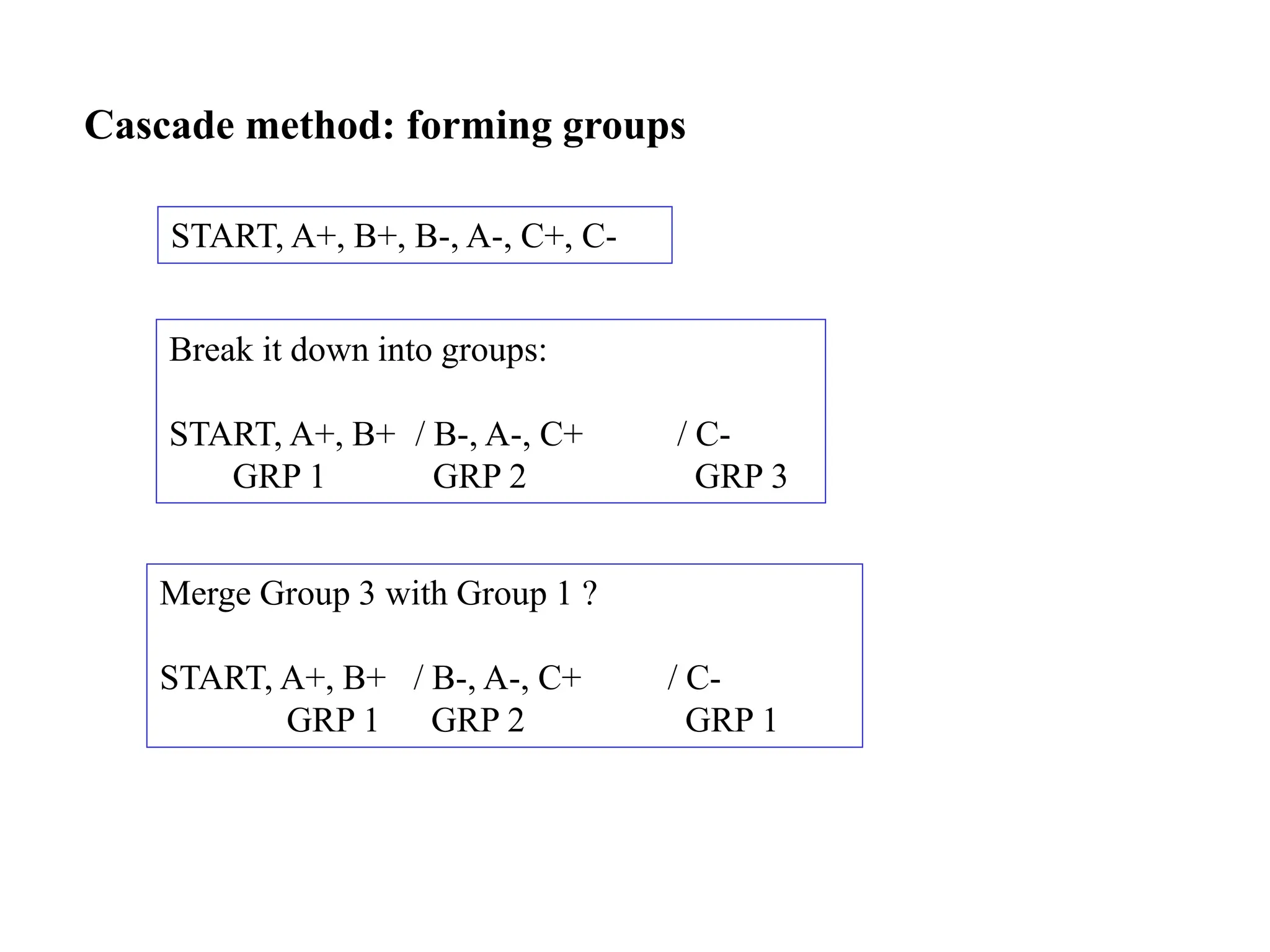
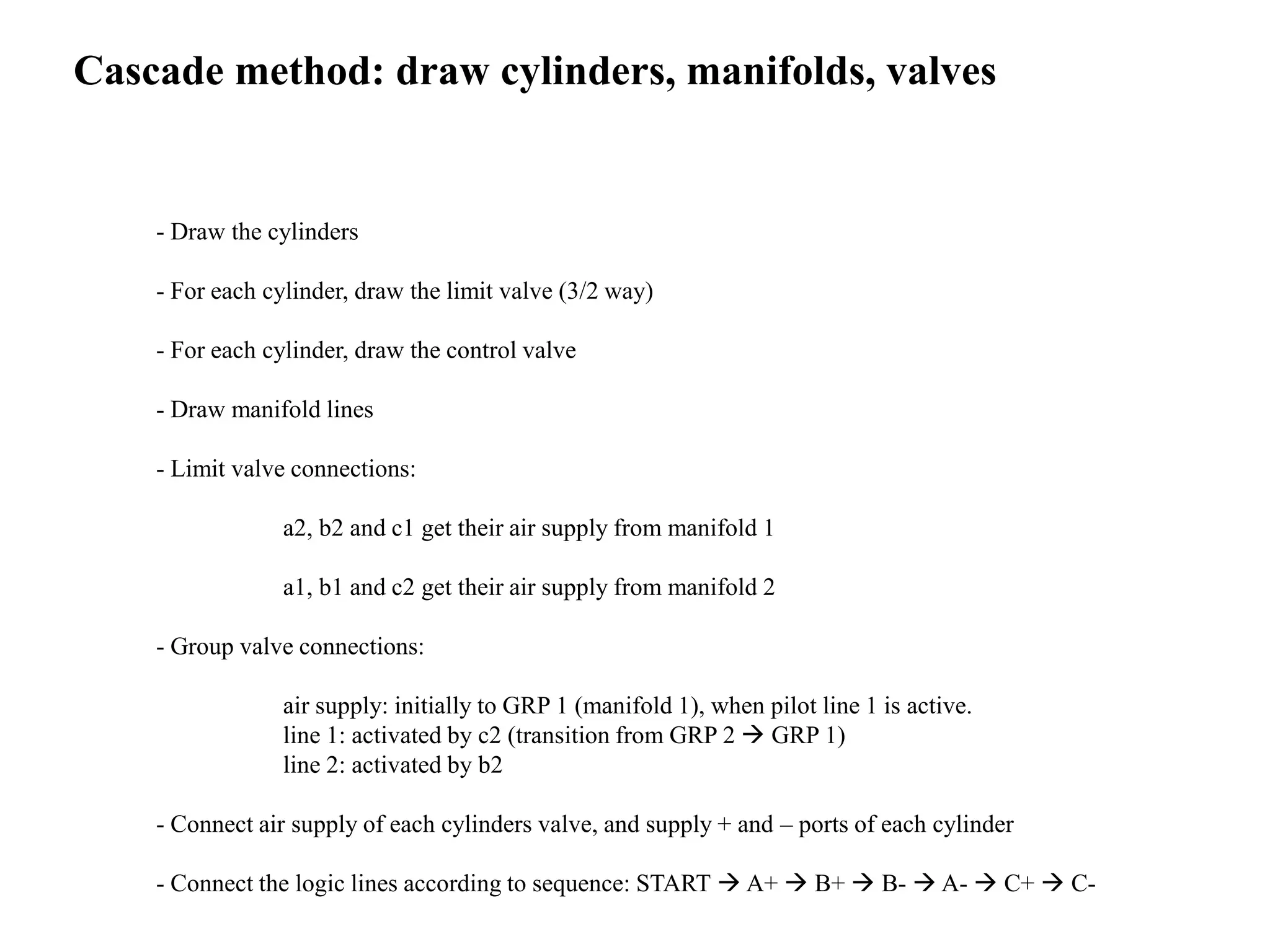
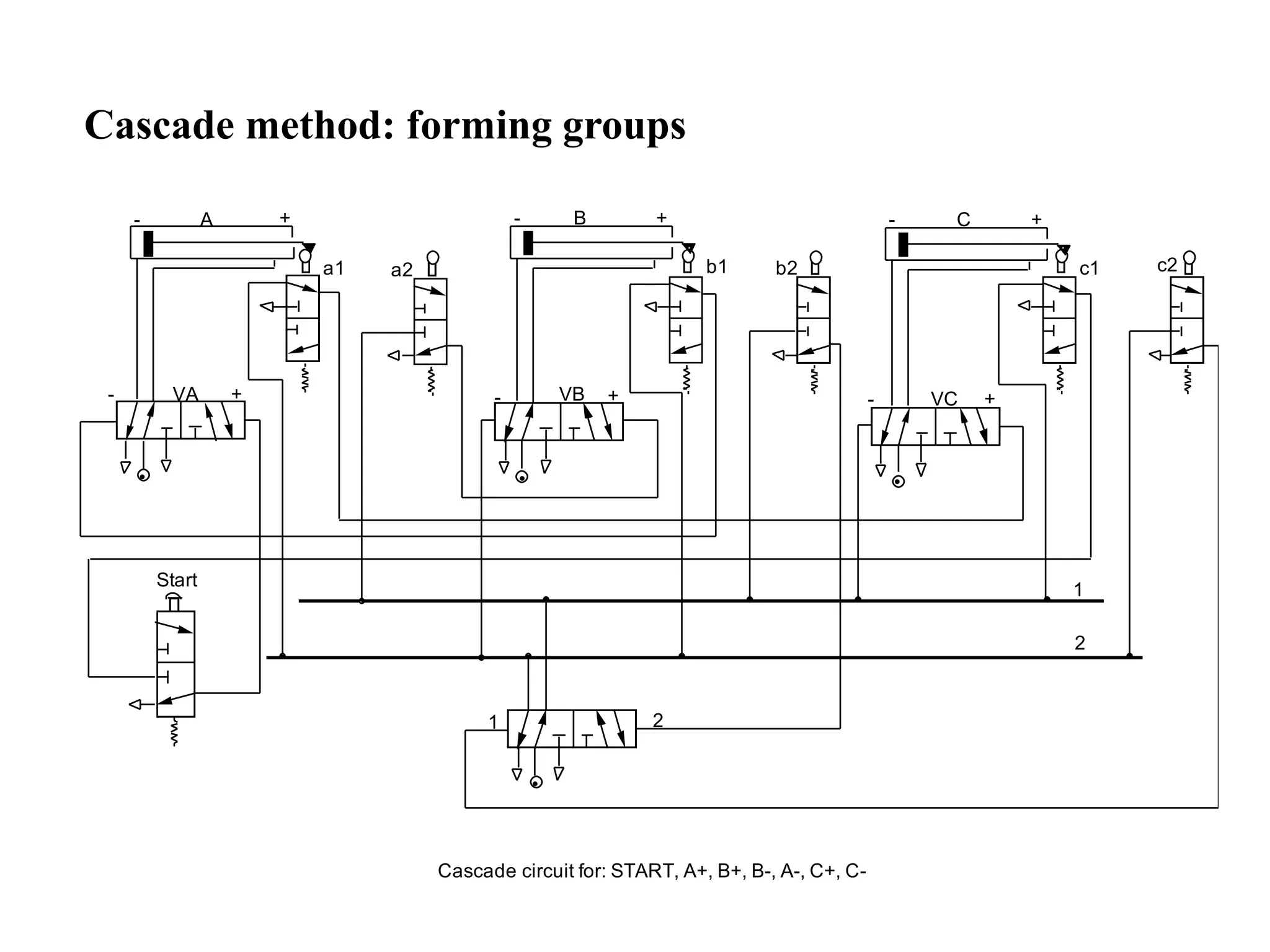
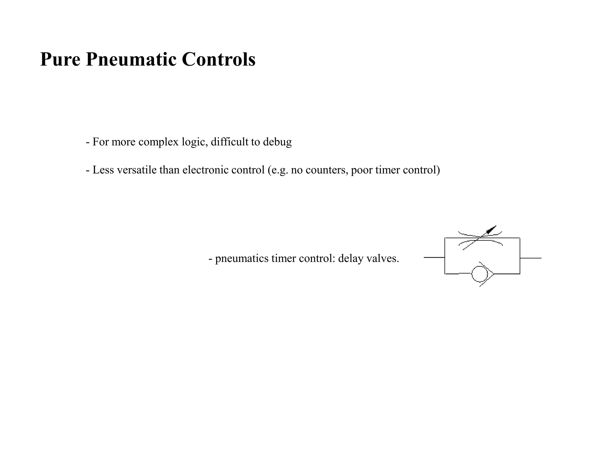
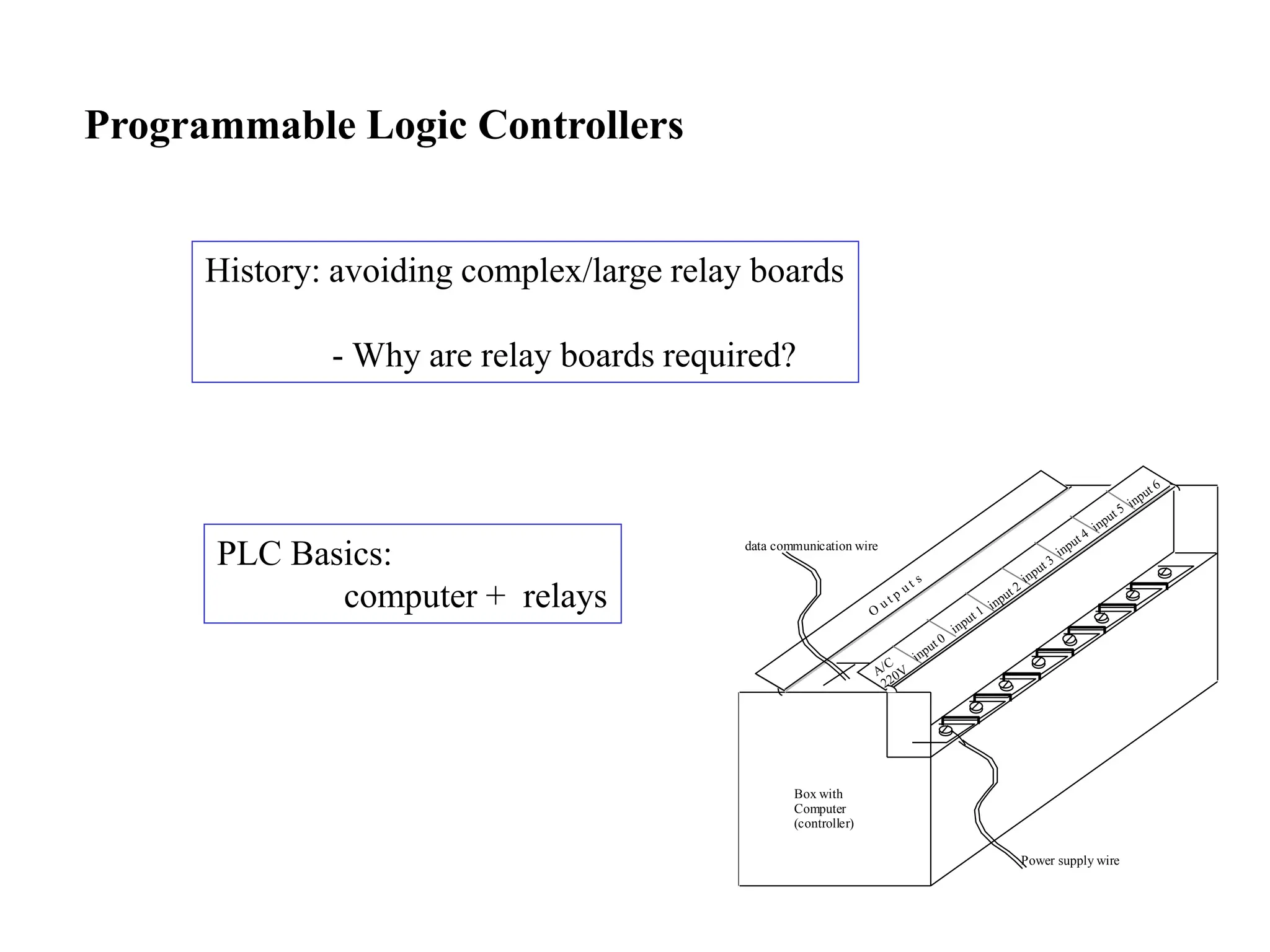
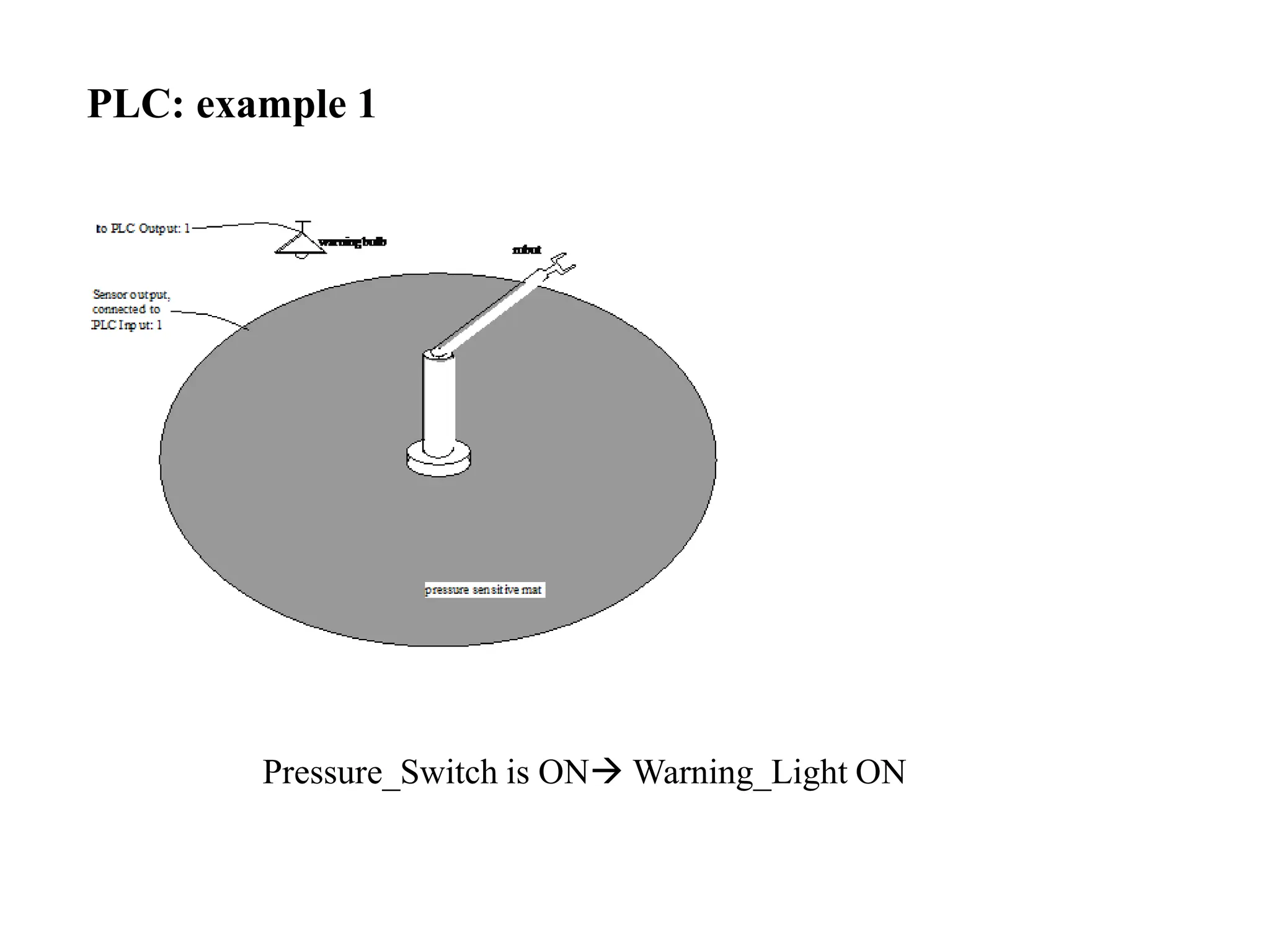
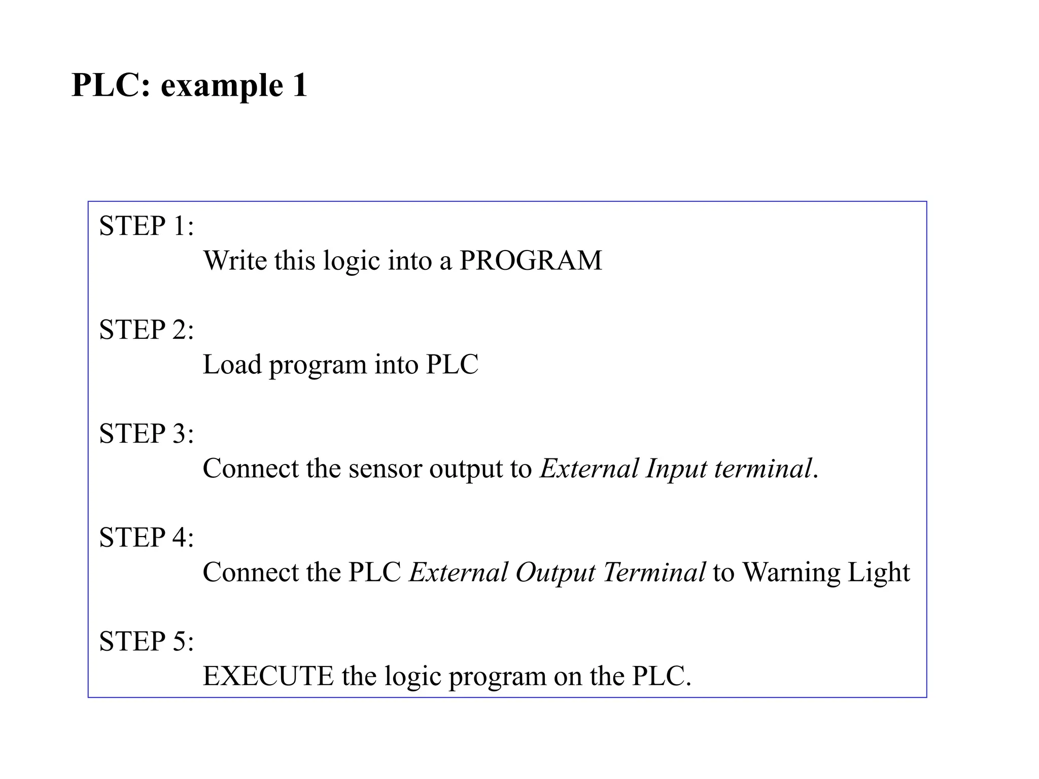
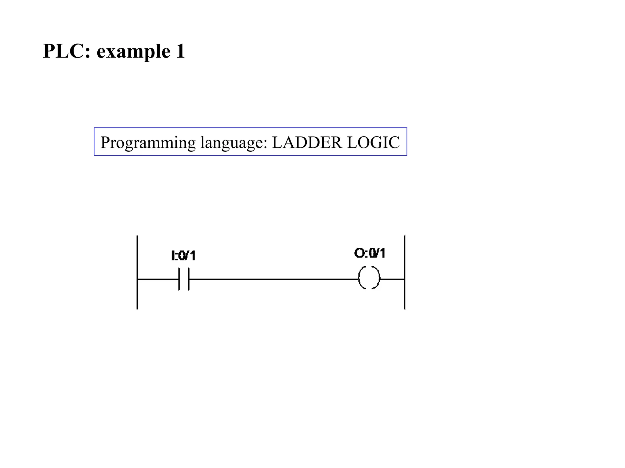
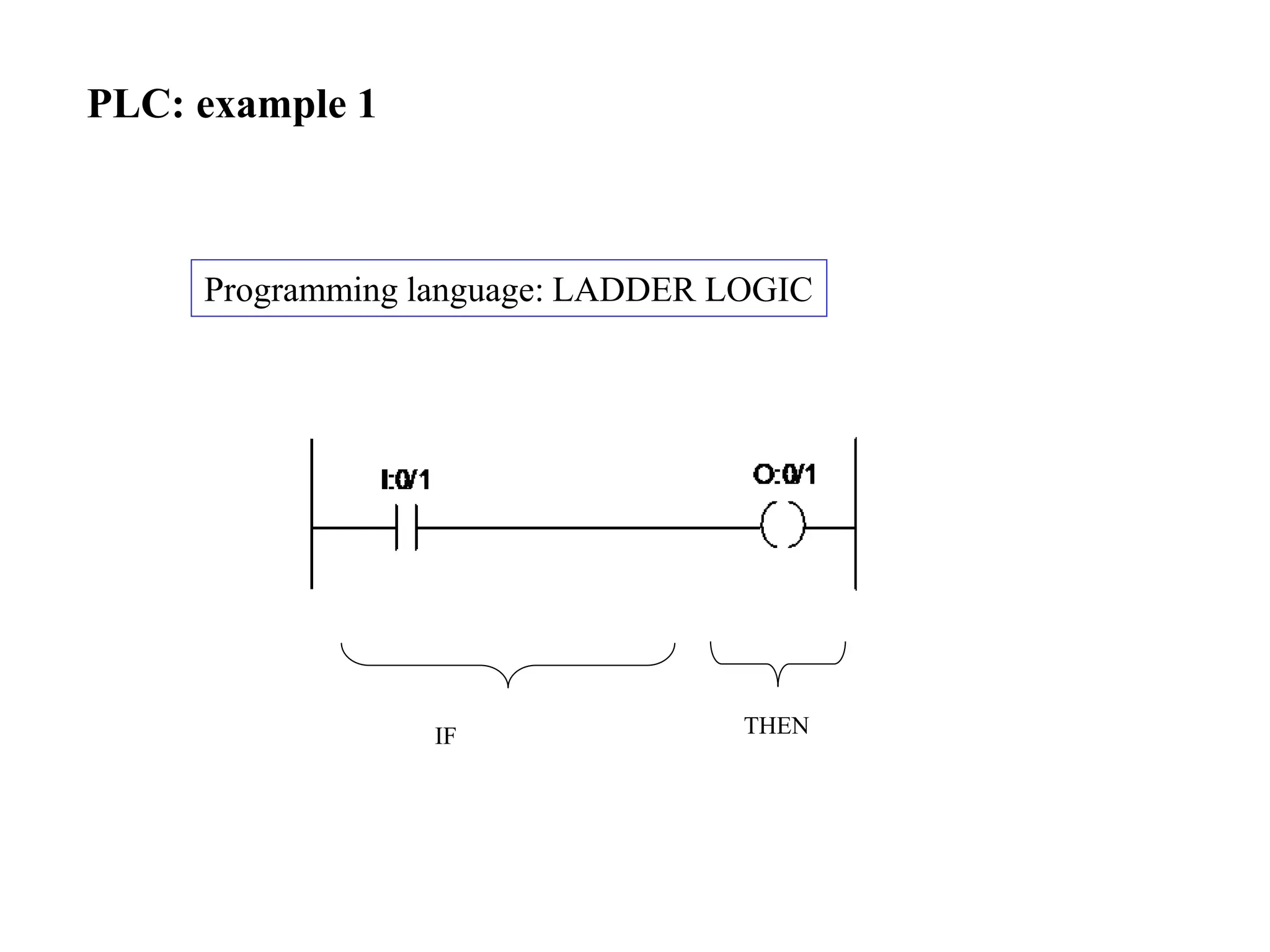
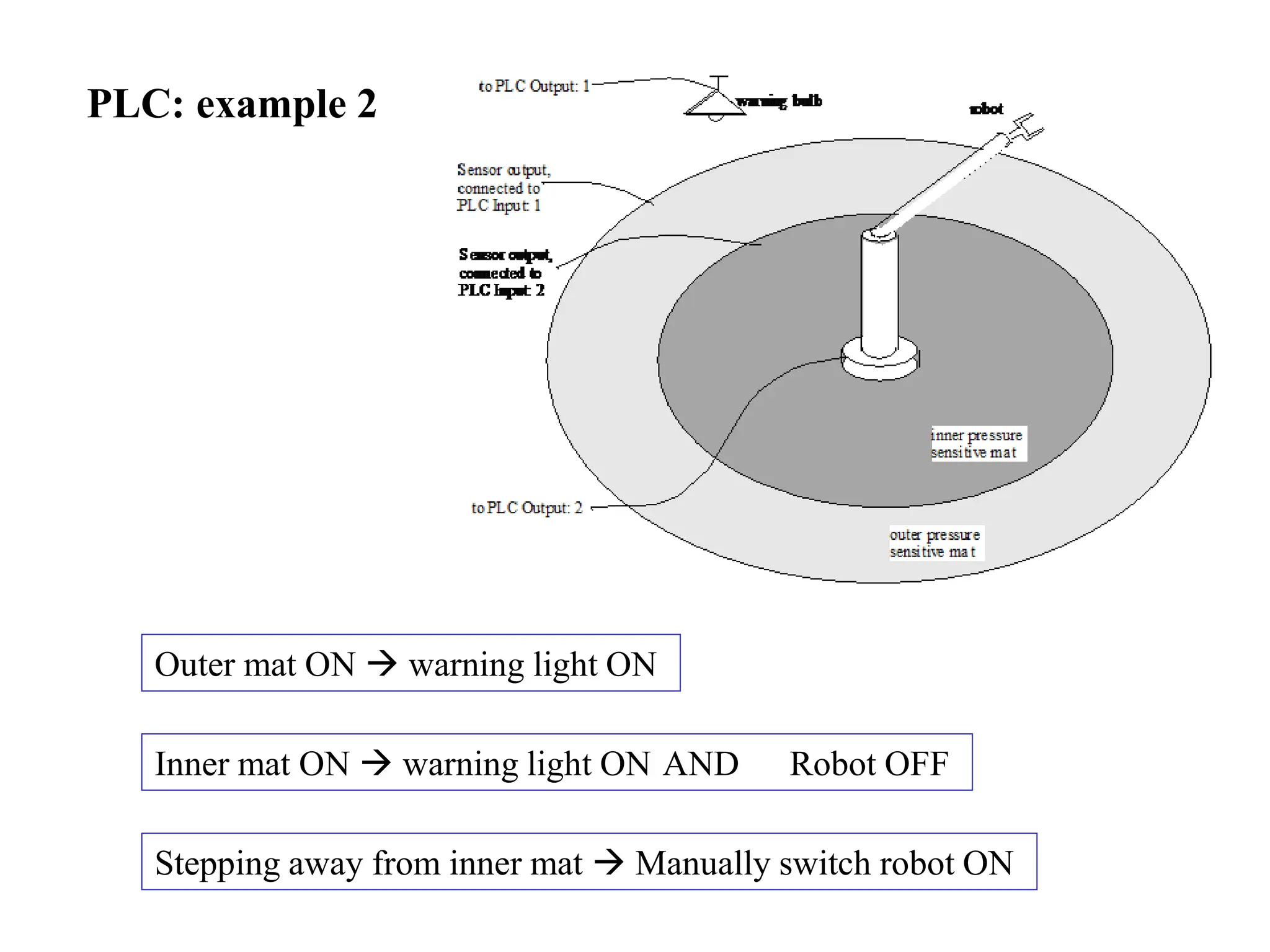
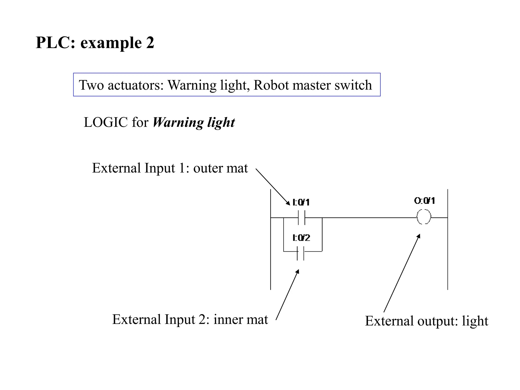
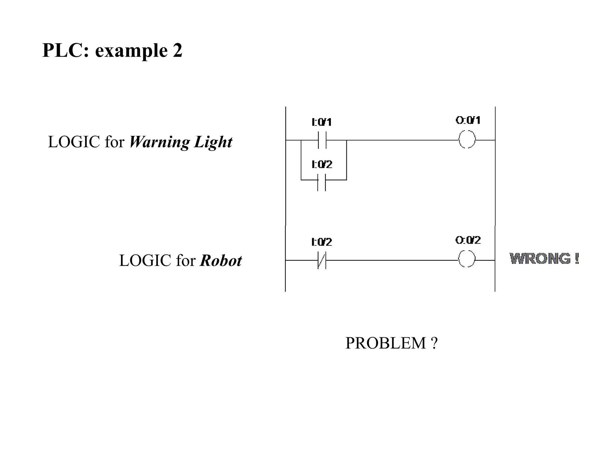
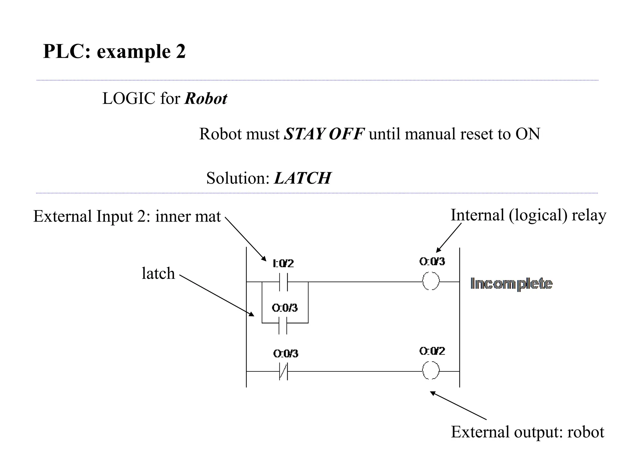
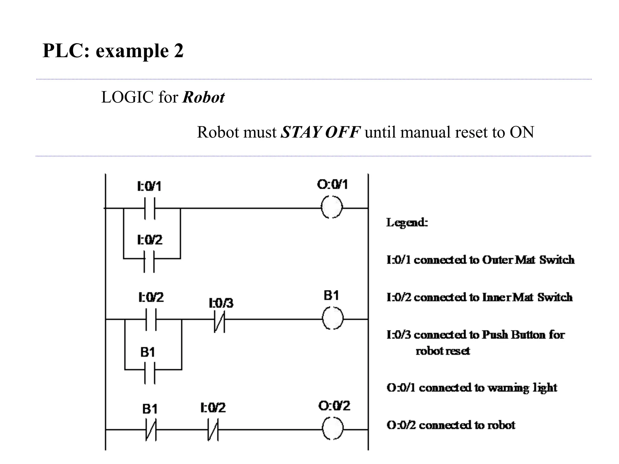
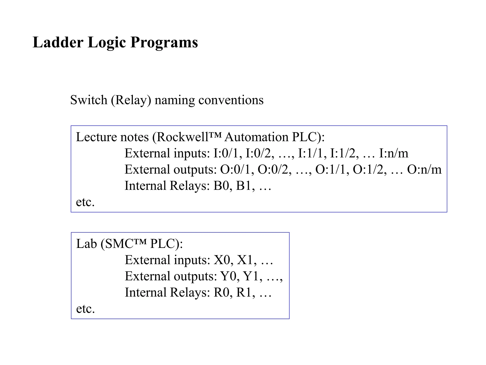
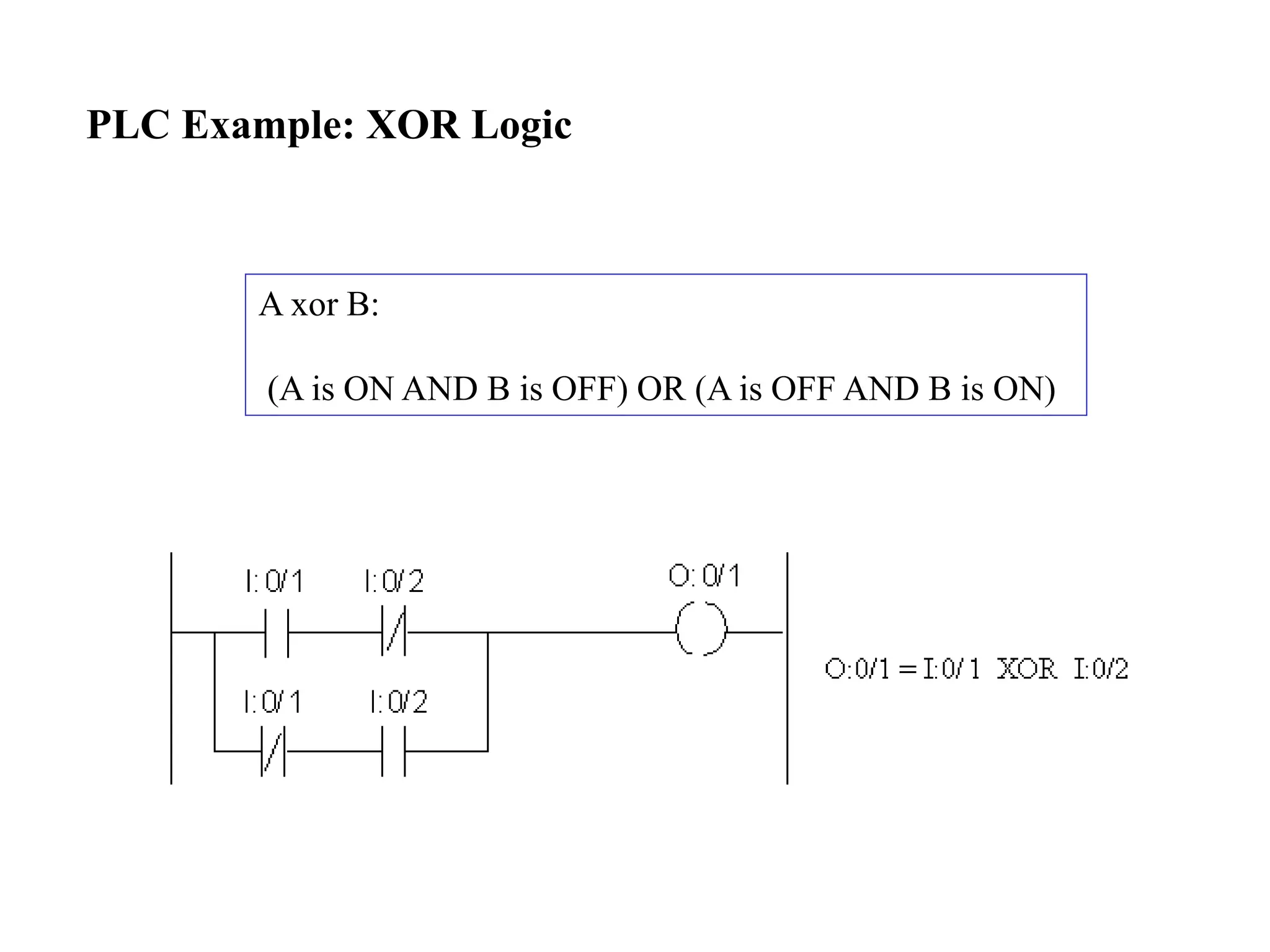
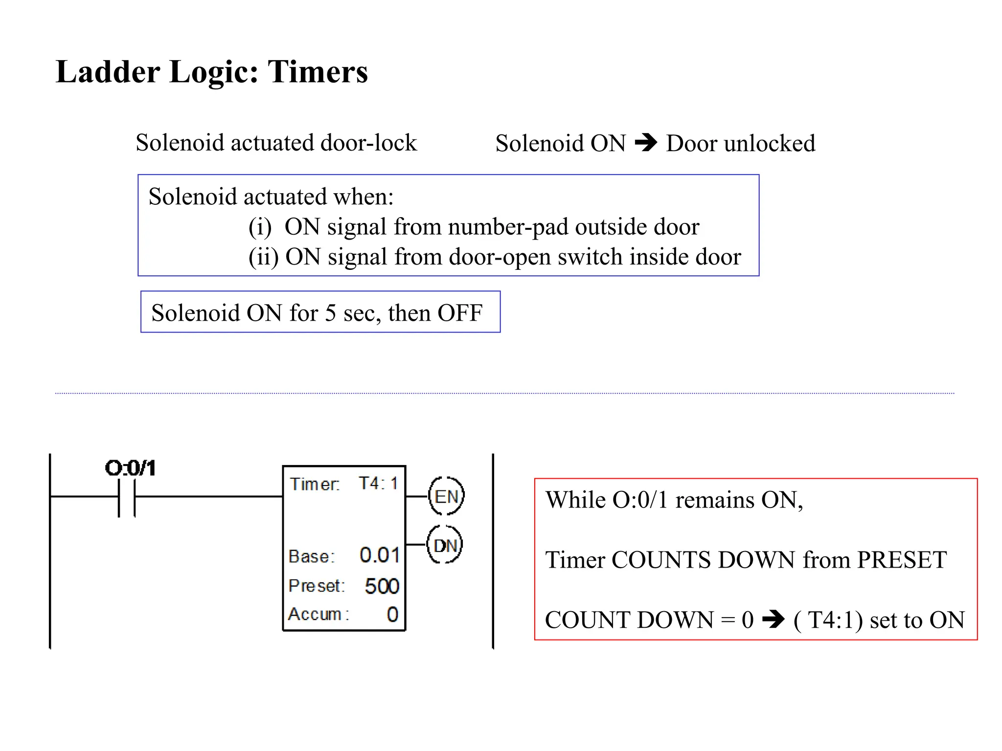
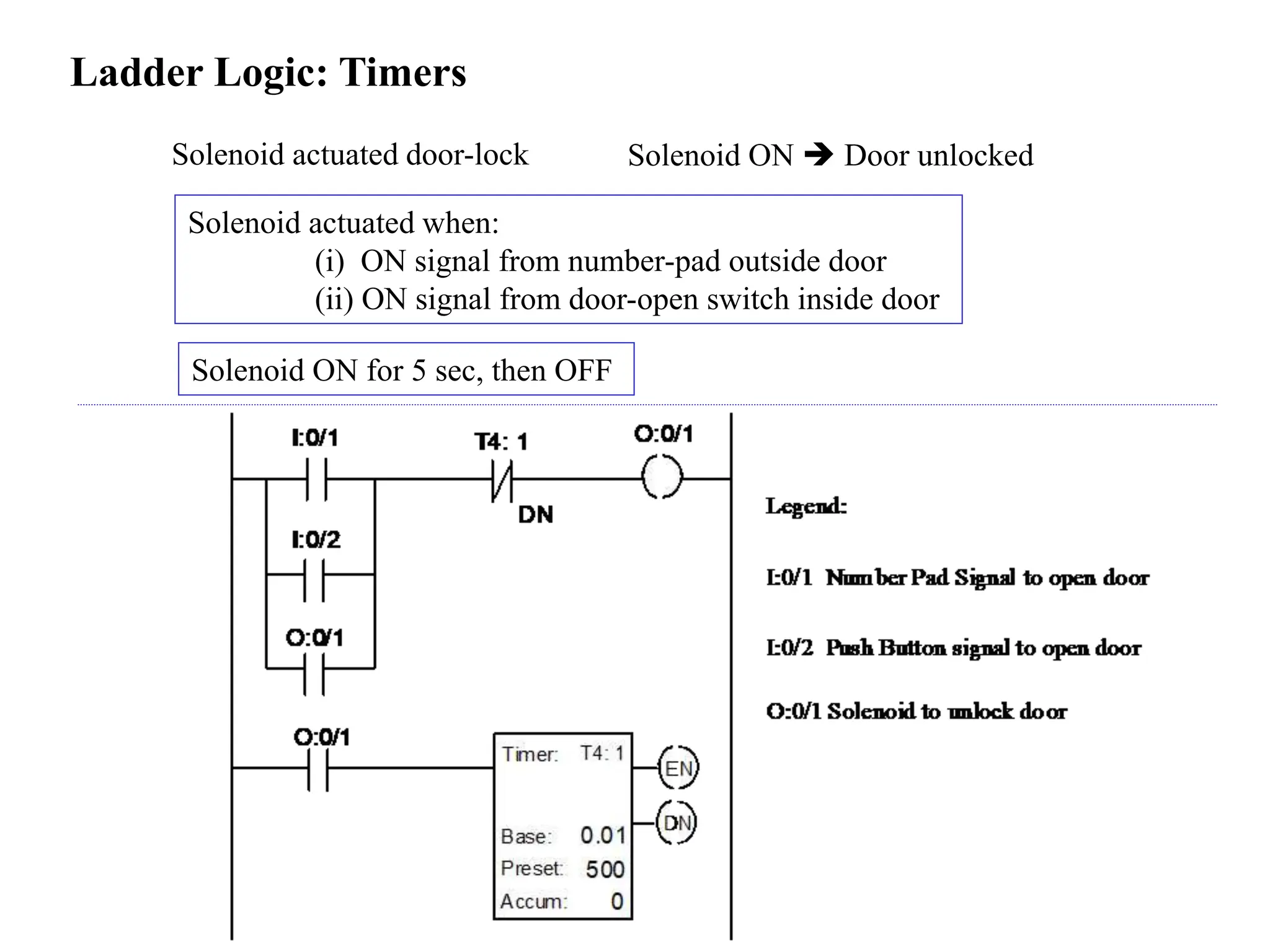
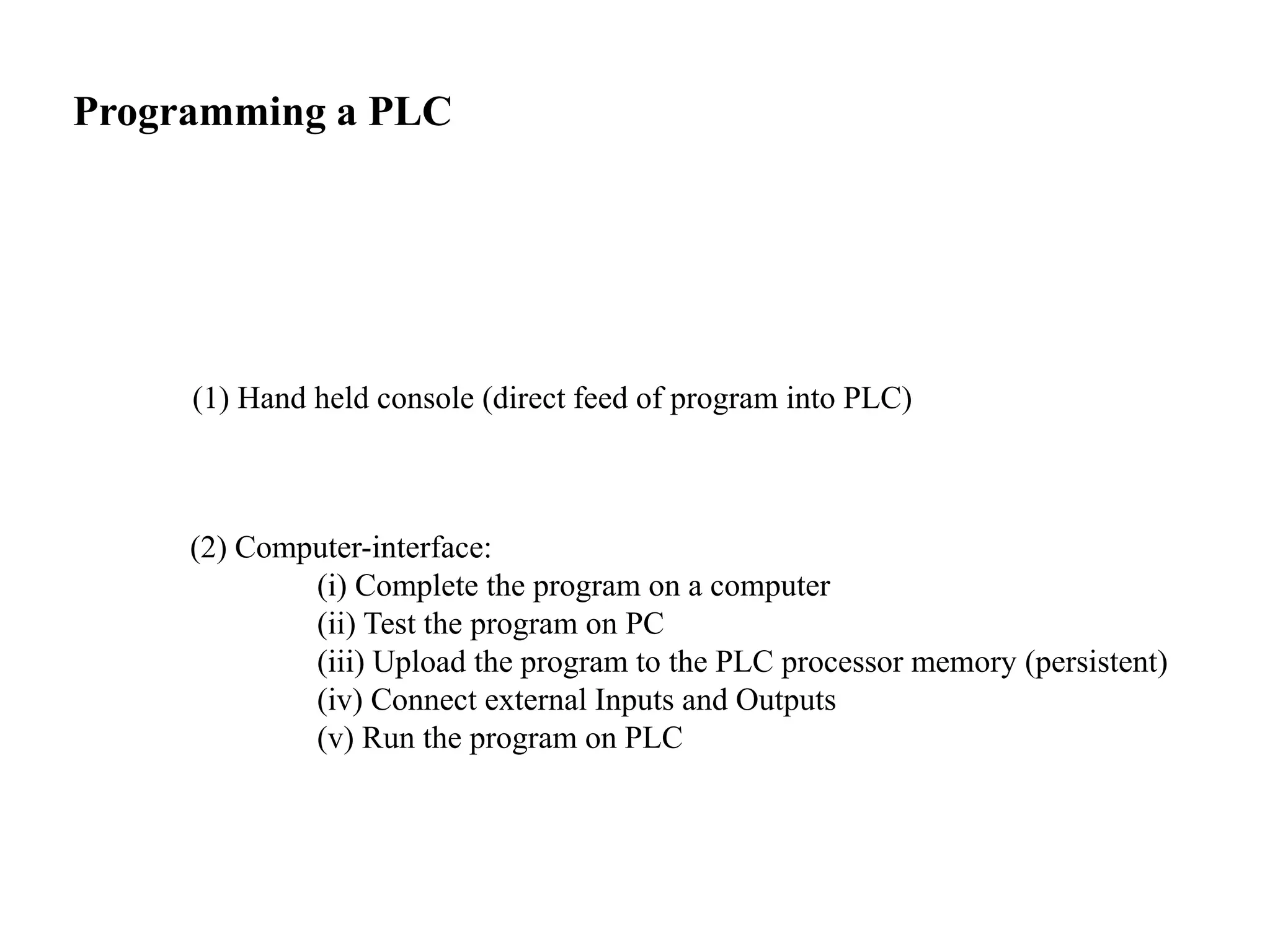
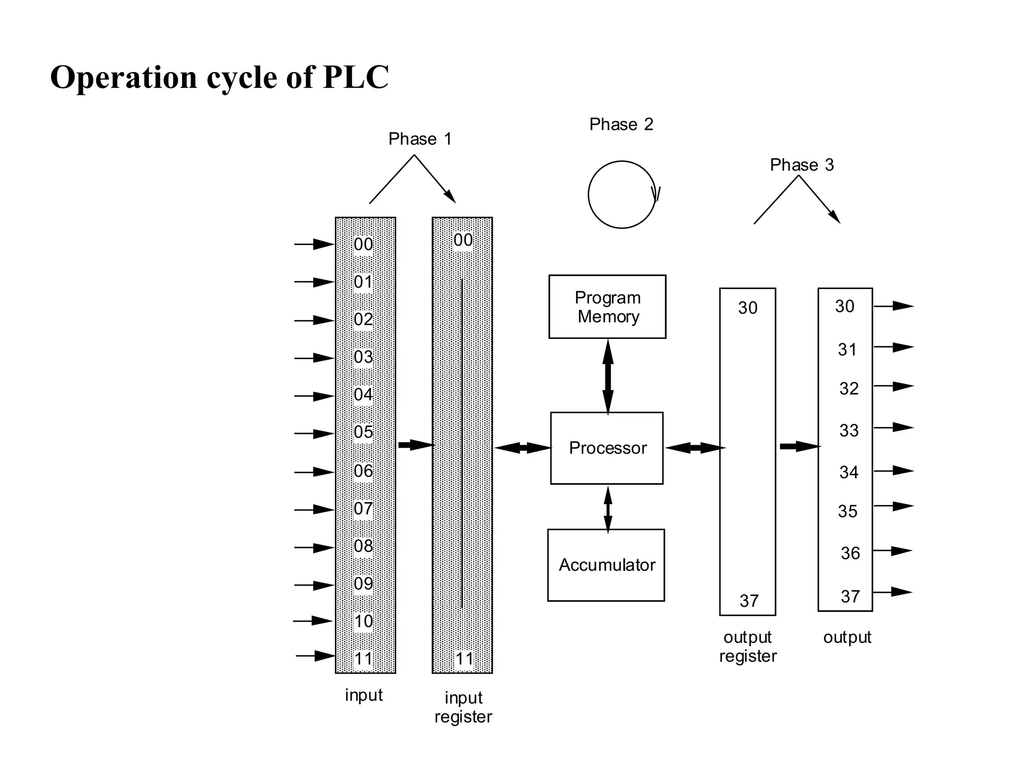
1. Discrete Control Logic
1. Pneumatic circuits - Low forces
- Discrete, fixed travel distances
- Rotational or reciprocating motion
Main components: compressor, valves, cylinders
2. •
double -acting
spring-return
air supply
vent to atmosphere (air discharge)
Pneumatic components: cylinders
tepping away from this mat, the person has to manually switch the robot back ON
3. Pneumatic components: valves
a 3/2 valve a 5/2 valve
return spring pneumatic
push button
foot pedal
solenoid (electrical) roller (mechanical)
valve actuation
5. Pure Pneumatic control design: Cascade method
Example: Punch Press Operation:
(i) part is clamped in position
(ii) press punches the part
(iii) the clamp is released
(iv) part is removed from the table
START, A+, B+, B-, A-, C+, C-
Functions of A, B, C ?
How to design pneumatic system?
6. Pure Pneumatic control design: Cascade method
(1) Write cylinder action sequence
(2) Partition sequence into minimum no. of groups (no letter repeated in group)
(3) Merge last group, first group (if possible)
(4) Each cylinder is double-acting
(5) Each cylinder is controlled by 5/2 valve (both pilot lines: pneumatic)
(6) Each + and – position of cylinder: limit valves
(7) Each group => manifold line.
The manifold line connects to the limit valves associated with the cylinders.
(8) The air pressure in the manifolds is controlled by 5/2 valves called group valves.
no. of group valves = (no of groups – 1)
7. Cascade method: forming groups
Break it down into groups:
START, A+, B+ / B-, A-, C+ / C-
GRP 1 GRP 2 GRP 3
START, A+, B+, B-, A-, C+, C-
Merge Group 3 with Group 1 ?
START, A+, B+ / B-, A-, C+ / C-
GRP 1 GRP 2 GRP 1
8. Cascade method: draw cylinders, manifolds, valves
- Draw the cylinders
- For each cylinder, draw the limit valve (3/2 way)
- For each cylinder, draw the control valve
- Draw manifold lines
- Limit valve connections:
a2, b2 and c1 get their air supply from manifold 1
a1, b1 and c2 get their air supply from manifold 2
- Group valve connections:
air supply: initially to GRP 1 (manifold 1), when pilot line 1 is active.
line 1: activated by c2 (transition from GRP 2 GRP 1)
line 2: activated by b2
- Connect air supply of each cylinders valve, and supply + and – ports of each cylinder
- Connect the logic lines according to sequence: START A+ B+ B- A- C+ C-
9. Cascade method: forming groups
Start
- + - + - +
•
•
•
•
A
a1 a2
B
b1 b2
C
c1 c2
- +
VC
+
- VB
- +
VA
1
2
2
1
Cascade circuit for: START, A+, B+, B-, A-, C+, C-
10. Pure Pneumatic Controls
- For more complex logic, difficult to debug
- Less versatile than electronic control (e.g. no counters, poor timer control)
- pneumatics timer control: delay valves.
11. Programmable Logic Controllers
History: avoiding complex/large relay boards
- Why are relay boards required?
PLC Basics:
computer + relays
A/C
220V
input 0
input 1 input 2
input 3
input 4
input 5 input 6
Power supply wire
O
u t p u t s
Box with
Computer
(controller)
data communication wire
13. PLC: example 1
STEP 1:
Write this logic into a PROGRAM
STEP 2:
Load program into PLC
STEP 3:
Connect the sensor output to External Input terminal.
STEP 4:
Connect the PLC External Output Terminal to Warning Light
STEP 5:
EXECUTE the logic program on the PLC.
16. PLC: example 2
Outer mat ON warning light ON
Inner mat ON warning light ON AND Robot OFF
Stepping away from inner mat Manually switch robot ON
17. PLC: example 2
Two actuators: Warning light, Robot master switch
LOGIC for Warning light
External Input 1: outer mat
External Input 2: inner mat External output: light
19. PLC: example 2
LOGIC for Robot
Robot must STAY OFF until manual reset to ON
Solution: LATCH
External Input 2: inner mat Internal (logical) relay
latch
External output: robot
22. PLC Example: XOR Logic
A xor B:
(A is ON AND B is OFF) OR (A is OFF AND B is ON)
23. Ladder Logic: Timers
Solenoid actuated door-lock
Solenoid ON for 5 sec, then OFF
Solenoid ON Door unlocked
Solenoid actuated when:
(i) ON signal from number-pad outside door
(ii) ON signal from door-open switch inside door
While O:0/1 remains ON,
Timer COUNTS DOWN from PRESET
COUNT DOWN = 0 ( T4:1) set to ON
24. Ladder Logic: Timers
Solenoid actuated door-lock
Solenoid ON for 5 sec, then OFF
Solenoid ON Door unlocked
Solenoid actuated when:
(i) ON signal from number-pad outside door
(ii) ON signal from door-open switch inside door
25. Ladder Logic: Timers -- reset
Solenoid ON for 5 sec, then OFF
Solenoid actuated when:
(i) ON signal from number pad outside door
(ii) ON signal from door-open switch inside door
During ON, if button is pressed,
Timer resets to PRESET
During ON, light indicator is ON
LEGEND:
I:0/1 door-open
I:O/2 card-reader
O:0/1 solenoid
O:0/2 light indicator
26. Ladder Logic: counters
Count the number of occurrences of an event
Pallet loading in factory
After 10 parts arrive on conveyor, worker comes to load pallet
Examples:
Pneumatic press hammer
Hit the part 20 times, then wait for part to be unloaded
Rice cooker alarm
Beep 5 times when rice is cooked
EVENT: switch goes from OFF ON
27. Ladder Logic: counters
Pallet loading in factory After 4 parts arrive on conveyor:
STOP conveyor belt
turn ON the indicator light
28. Ladder Logic: car wash
Car arrives limit switch ON
Limit switch ON Washer ON
Washer ON:
(i) Soapy water SPRAY ON (30 secs)
(ii) Rinse: clean water SPRAY ON (30 secs)
(iii) Automatic scrubber brushes car (15 secs)
(iv) After washing 50 cars, the scrubber brush Auto-change
29. I:0/1 I:0/2 B1
O:0/0
B1 T4:0 T4:1 T4:2
O:0/1
B1
O:0/2
B1
O:0/3
B1
B1
B1
I:0/1 : System On
I:0/2 : Emergency Stop
I:0/3 : Limit Switch
O:0/0 : Soap Water On
O:0/1 : Rinse On
O:0/2 : Scrubber On
O:0/3 : Activate Scrubber Change
Notice how B1 and the timer outputs are
used to control the logic
according to the required timing.
O:0/2
Preset:
Accum:
T4: 1
6000
0
Base: 0.01
Preset:
Accum:
T4: 2
7500
0
Base: 0.01
Preset:
Accum:
T4: 0
3000
0
Base: 0.01
DN
T4:0
DN
T4:0
DN
DN
T4:1
DN
T4:1
DN
DN
T4:2
DN
T4:2
DN
Preset:
Accum:
C5: 0
50
0
CTU
I:0/3 T4:0
RES
I:0/3 T4:1
RES
I:0/3 T4:2
RES
O:0/3 C5:0
RES
C5: 0
DN
EN
EN
EN
EN
Car arrives limit switch ON
Limit switch ON Washer ON
Washer ON:
(i) Soapy water SPRAY ON (30 secs)
(ii) Rinse: clean water SPRAY ON (30 secs)
(iii) Automatic scrubber brushes car (15 secs)
(iv) After washing 50 cars, the scrubber brush Auto-change
30. Programming a PLC
(1) Hand held console (direct feed of program into PLC)
(2) Computer-interface:
(i) Complete the program on a computer
(ii) Test the program on PC
(iii) Upload the program to the PLC processor memory (persistent)
(iv) Connect external Inputs and Outputs
(v) Run the program on PLC