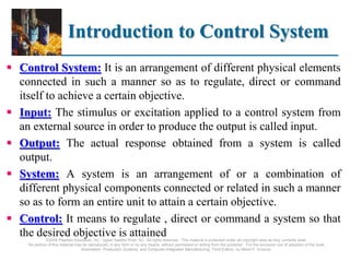
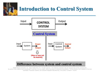
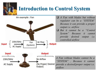
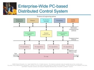
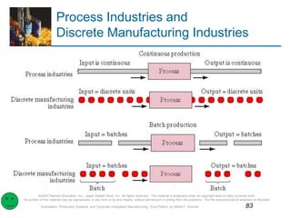
SlideShare a Scribd company logo
1 of 83
©2008 Pearson Education, Inc., Upper Saddle River, NJ. All rights reserved. This material is protected under all copyright laws as they currently exist.
No portion of this material may be reproduced, in any form or by any means, without permission in writing from the publisher. For the exclusive use of adopters of the book
Automation, Production Systems, and Computer-Integrated Manufacturing, Third Edition, by Mikell P. Groover.
Ch 5 Industrial Control
Systems
Outlines:
1. Introduction to control system
2. Industrial Automation vs.
Industrial Information Technology
3. Process Industries vs. Discrete
Manufacturing Industries
4. Classification of Control System
5. Continuous vs. Discrete Control
6. Computer Process Control
Introduction to Control System
 Control System: It is an arrangement of different physical elements
connected in such a manner so as to regulate, direct or command
itself to achieve a certain objective.
 Input: The stimulus or excitation applied to a control system from
an external source in order to produce the output is called input.
 Output: The actual response obtained from a system is called
output.
 System: A system is an arrangement of or a combination of
different physical components connected or related in such a manner
so as to form an entire unit to attain a certain objective.
 Control: It means to regulate , direct or command a system so that
the desired objective is attained
©2008 Pearson Education, Inc., Upper Saddle River, NJ. All rights reserved. This material is protected under all copyright laws as they currently exist.
No portion of this material may be reproduced, in any form or by any means, without permission in writing from the publisher. For the exclusive use of adopters of the book
Automation, Production Systems, and Computer-Integrated Manufacturing, Third Edition, by Mikell P. Groover.
Introduction to Control System
©2008 Pearson Education, Inc., Upper Saddle River, NJ. All rights reserved. This material is protected under all copyright laws as they currently exist.
No portion of this material may be reproduced, in any form or by any means, without permission in writing from the publisher. For the exclusive use of adopters of the book
Automation, Production Systems, and Computer-Integrated Manufacturing, Third Edition, by Mikell P. Groover.
Difference between system and control system
Control System
Introduction to Control System
©2008 Pearson Education, Inc., Upper Saddle River, NJ. All rights reserved. This material is protected under all copyright laws as they currently exist.
No portion of this material may be reproduced, in any form or by any means, without permission in writing from the publisher. For the exclusive use of adopters of the book
Automation, Production Systems, and Computer-Integrated Manufacturing, Third Edition, by Mikell P. Groover.
A Fan without blades cannot be a
“SYSTEM” , Because it cannot
provide a desired/proper output i.e.
airflow
 A Fan with blades but without
regulator can be a “SYSTEM”
Because it can provide a proper
output i.e. airflow
 But it cannot be a “Control
System” Because it cannot
provide desired output i.e.
controlled airflow
Levels of automation in the
two Industries
 Significant differences are seen in the low and intermediate levels.
 Device level: There are differences in the types of actuators and sensors
used.
 Process industries: the devices are used mostly for the control loops
in chemical, thermal, or similar processing operations.
 Discrete manufacturing: the devices control the mechanical actions
of machines.
 At level 2: the difference is that unit operations are controlled in the process
industries, and machines are controlled in discrete manufacturing operations.
 At level 3: the difference is between control of interconnected unit
processing operations and interconnected machines.
 At the upper levels (plant and enterprise): the control issues are similar,
allowing for the fact that the products and processes are different.
©2008 Pearson Education, Inc., Upper Saddle River, NJ. All rights reserved. This material is protected under all copyright laws as they currently exist.
No portion of this material may be reproduced, in any form or by any means, without permission in writing from the publisher. For the exclusive use of adopters of the book
Automation, Production Systems, and Computer-Integrated Manufacturing, Third Edition, by Mikell P. Groover.
Levels of automation in the
two Industries
Table 5.2 Levels of Automation in the Process Industries and
Discrete Manufacturing Industries
©2008 Pearson Education, Inc., Upper Saddle River, NJ. All rights reserved. This material is protected under all copyright laws as they currently exist.
No portion of this material may be reproduced, in any form or by any means, without permission in writing from the publisher. For the exclusive use of adopters of the book
Automation, Production Systems, and Computer-Integrated Manufacturing, Third Edition, by Mikell P. Groover.
A Hierarchy of Control Issues
in Manufacturing
©2008 Pearson Education, Inc., Upper Saddle River, NJ. All rights reserved. This material is protected under all copyright laws as they currently exist.
No portion of this material may be reproduced, in any form or by any means, without permission in writing from the publisher. For the exclusive use of adopters of the book
Automation, Production Systems, and Computer-Integrated Manufacturing, Third Edition, by Mikell P. Groover.
Level 4: Plant: control decisions are less concerned with the daily operation of the
factory and are more closely related to the business objectives of the firm. A typical plant-
level control decision is aggregate production planning, which refers to the process of
planning the use of the production capacity of the plant to meet customer demands over a
period of months or a year. The output of this plan is a schedule of which products will be
produced during each period of time going forward over the period of the plan
 Order processing
 Purchasing
 Aggregate production
planning
 Accounting
Level 3: factory floor control: decisions are made that affect groups of production
lines or work cells. For example, several production lines or work cells may be serviced by
the same materials handling system that brings raw materials from storage to production to
be manufactured into finished product. Since this materials handling resource is shared
among production lines and work cells, there must be a supervisory level of decision
making that decides how to allocate this resource, particularly when conflict occurs, i.e.
when it is required to service two lines at the same time.
 Materials management
 Quality management
 Shop-floor scheduling
Level 2-Work cell/ production line: the objective is to supervise the interactions
between a group of related machines or processes. This level of control is not concerned
with the operation of the machine or process itself - that is the responsibility of the machine
control level.
 Materials handling
 Part sequencing
 Inspection/Statistical
process control
Level 1-The machine control: is responsible for ensuring that the sequence of
machine operations correspond to the planned sequence, or programmed steps. Typically,
the sequence of operations is carried out as prescribed by the program resident in the
machine controller and there are few or no decisions to be made.
 CNC machine tools
 Robots
 Programmable controllers
©2008 Pearson Education, Inc., Upper Saddle River, NJ. All rights reserved. This material is protected under all copyright laws as they currently exist.
No portion of this material may be reproduced, in any form or by any means, without permission in writing from the publisher. For the exclusive use of adopters of the book
Automation, Production Systems, and Computer-Integrated Manufacturing, Third Edition, by Mikell P. Groover.
Classification of Control System
 In general control systems are classified into two categories—open loop and
closed loop. Depending upon the nature of signals involved like electrical,
mechanical, hydraulic, pneumatic or combination of these signals, the control
systems may be classified as single input-single output (SISO) and multiple
input-multiple output (MIMO) systems.
 SISO system. As the name indicates, it is a system having a single input and a
single controlled variable. The output is produced by the single input solely.
Only one input signal flows or passes through the system. The examples of
SISO systems are voltage regulators, temperature controllers and so on.
 MIMO system. There are certain systems having multiple inputs and multiple
outputs. The systems in which any change in one of the outputs causes a
subsequent change in the other output during transient and steady state
conditions are called MIMO systems. The examples are boiler in which the
controlled variables are steam pressure, temperature, water level and so on.
Figure shows block diagram of an MIMO system.
©2008 Pearson Education, Inc., Upper Saddle River, NJ. All rights reserved. This material is protected under all copyright laws as they currently exist.
No portion of this material may be reproduced, in any form or by any means, without permission in writing from the publisher. For the exclusive use of adopters of the book
Automation, Production Systems, and Computer-Integrated Manufacturing, Third Edition, by Mikell P. Groover.
Classification of Control System
1. Linear & Non-linear Control Systems: A linear control system consists
of the components having a linear relationship between the input and
output signals under steady state conditions. Any system is called linear
when the principle of superposition is applied. A non-linear control
system consists of one or more elements, which exhibits a non-linear
relationship between the input and output signals. In such system, principle
of superposition is not applicable.
2. Linear-time Varying & Time-invariant Systems: In a control system,
most physical systems are characterized by differential equations. A
differential equation is linear if the coefficients are constants or functions
only of an independent variable. If the coefficients of describing
differential equations are functions of time, then the mathematical model is
time varying. The systems which consist of linear time-variant components
or elements described by linear time-variant differential equations, whose
coefficients are functions of time, are called linear time-varying systems.
©2008 Pearson Education, Inc., Upper Saddle River, NJ. All rights reserved. This material is protected under all copyright laws as they currently exist.
No portion of this material may be reproduced, in any form or by any means, without permission in writing from the publisher. For the exclusive use of adopters of the book
Automation, Production Systems, and Computer-Integrated Manufacturing, Third Edition, by Mikell P. Groover.
Classification of Control System
 On the other hand, dynamic systems that are composed of linear time-invariant
components by linear time-invariant differential equations are called linear time-
invariant systems (parameters do not vary with time).
3. Lumped Parameter & Distributed Parameter Control :The control system
which can be described by ordinary differential equations is called lumped
parameter control system. On the other hand, the control system which can be
represented by partial differential equations, is called distributed parameter
control system..
4. Deterministic And Stochastic Control System: In any control system if the
response to input is predictable and repeatable, then the system is called
deterministic control system. If the response to input is unpredictable and non-
repeatable, then the system is called stochastic control system.
5. Continuous-time & Discrete-time Control Systems: A control system in which
all the system parameters are continuous functions of time t is called continuous-
time control system. A control system in which all the system parameters are
discrete functions of time t is called discrete-time control system.
 This paradigm has led to modeling the manufacturing
problem as a hierarchy of decisions, where the upper
levels of the hierarchy place constraints on each
succeeding lower level. The objective is to assign each
control decision to the lowest possible level in the
hierarchy.
 The complete integration of all of these levels of
decision processes, supported by computer information
systems, is often referred to as computer-integrated
manufacturing.
©2008 Pearson Education, Inc., Upper Saddle River, NJ. All rights reserved. This material is protected under all copyright laws as they currently exist.
No portion of this material may be reproduced, in any form or by any means, without permission in writing from the publisher. For the exclusive use of adopters of the book
Automation, Production Systems, and Computer-Integrated Manufacturing, Third Edition, by Mikell P. Groover.
Industrial Control Systems
Automation Systems vs.
Control Systems
 It is important at this stage to understand some of the differences in
the senses that these two terms are generally interpreted in technical
contexts and specifically in this course. These are given below.
1. Control Systems: the main function of control systems is to
ensure that outputs follow the set points.
2. Automation Systems: may have much more functionality,
such as computing set points for control systems, monitoring
system performance, plant startup or shutdown, job and
equipment scheduling, ….etc. Automation Systems are
essential for most modern industries.
 Automation Systems may include Control Systems but the reverse
is not true. Control Systems may be parts of Automation Systems.
Industrial Automation vs.
Industrial Information Technology
 Industrial Automation makes extensive use of Information Technology. Some of the major IT
areas that are used in the context of Industrial Automation are:
1. Control and Signal Processing
2. Simulation, Design, Analysis, Optimization
3. Communication and Networking
4. Real-time Computing
5. Database
 However, Industrial Automation is distinct from IT in the following senses:
 Industrial Automation also involves significant amount of hardware technologies, related to
Instrumentation and Sensing, Actuation and Drives, Electronics for Signal Conditioning,
Communication and Display, Embedded as well as Stand-alone Computing Systems etc.
 As Industrial Automation systems grow more sophisticated in terms of the knowledge and
algorithms they use, as they encompass larger areas of operation comprising several units or
the whole of a factory, or even several of them, and as they integrate manufacturing with other
areas of business, such as, sales and customer care, finance and the entire supply chain of the
business, the usage of IT increases dramatically. However, the lower level Automation
Systems that only deal with individual or , at best, a group of machines, make less use of IT
and more of hardware, electronics and embedded computing.
Features of IT
 There are some other distinguishing features of IT for the factory that differentiate it
with its more ubiquitous counterparts that are used in offices and other business.
Industrial information systems are generally
I. Reactive in the sense that they receive stimuli and in turn produce responses.
Naturally, a crucial component of an industrial information system is its interface.
II. Have to be real-time, by that we mean that the computation not only has to be
correct, but also must be produced in time. An accurate result, which is not timely
may be less preferable than a less accurate result produced in time. Therefore
systems have to be designed with clear considerations of meeting computing time
deadlines.
III. Considered mission-critical, in the sense that the malfunctioning can bring about
catastrophic consequences in terms of loss of human life or property. Therefore
extraordinary care must be exercised during their design to make them flawless. In
spite of that, elaborate mechanisms are often deployed to ensure that any unforeseen
circumstances can also be handled in a predictable manner. Fault-tolerance to
emergencies due to hardware and software faults must often be built in.
©2008 Pearson Education, Inc., Upper Saddle River, NJ. All rights reserved. This material is protected under all copyright laws as they currently exist.
No portion of this material may be reproduced, in any form or by any means, without permission in writing from the publisher. For the exclusive use of adopters of the book
Automation, Production Systems, and Computer-Integrated Manufacturing, Third Edition, by Mikell P. Groover.
Industrial Control - Defined
 The control system is one of the three basic components of an automated
system (Lecture1). This lecture focuses on industrial control systems, in
particular how digital computers are used to implement the control function in
production.
 By industrial control systems, we denote the sensors systems, actuator
systems as a controller. Controllers are essentially (predominantly electronic,
at times pneumatic/hydraulic) elements that accept command signals from
human operators or supervisory Systems, as well as feedback from the process
sensors and produce or compute signals that are fed to the actuators.
 Industrial control is the automatic regulation of unit operations and their
associated equipment as well as the integration and coordination of the unit
operations into the larger production system
 Unit operation
 Usually refers to a manufacturing operation
 Can also apply to material handling or other equipment
©2008 Pearson Education, Inc., Upper Saddle River, NJ. All rights reserved. This material is protected under all copyright laws as they currently exist.
No portion of this material may be reproduced, in any form or by any means, without permission in writing from the publisher. For the exclusive use of adopters of the book
Automation, Production Systems, and Computer-Integrated Manufacturing, Third Edition, by Mikell P. Groover.
Process Industries vs.
Discrete Manufacturing Industries
 Process industries
Production operations are performed on amounts of
materials: liquids, gases, powders, etc.
 Discrete manufacturing industries
Production operations are performed on quantities of
materials: Parts, product units
 The kinds of unit operations performed on the materials are
different in the two industry categories.
Figure 5.1
Process Industries Versus discrete
Manufacturing Industries
©2008 Pearson Education, Inc., Upper Saddle River, NJ. All rights reserved. This material is protected under all copyright laws as they currently exist.
No portion of this material may be reproduced, in any form or by any means, without permission in writing from the publisher. For the exclusive use of adopters of the book
Automation, Production Systems, and Computer-Integrated Manufacturing, Third Edition, by Mikell P. Groover.
7/65
Definitions: Variable and
Parameters
 Variables - outputs of the process
 Parameters - inputs to the process
 Continuous variables and parameters - they are uninterrupted as time proceeds (e.g. flow
rate, force , temperature, pressure & velocity) are continuous over time during the process.
 Also considered to be analog - can take on any of an infinite number of possible values
within a certain practical range.
 They are not restricted to a discrete set of values
 Discrete variables and parameters - can take on only certain values within a given range.
The most common types of discrete variable and parameters are:
1) Binary, i.e., ON/OFF, open/closed, and so on, i.e., limit switch open/closed, motor on/off,
work part present/not present.
2) Discrete, are variables that can take on more than two possible values but less than an infinite
number. Examples include daily piece counts in a production operation and the display of a
digital tachometer.
3) Pulse data, which consist of a series of pulses (called a pulse train). As a process variable, it
might be used to indicate piece counts, i.e.; parts passing on a conveyor activate a photocell to
produce a pulse for each part detected. As a process parameter, a pulse train might be used to
drive a stepper motor.
©2008 Pearson Education, Inc., Upper Saddle River, NJ. All rights reserved. This material is protected under all copyright laws as they currently exist.
No portion of this material may be reproduced, in any form or by any means, without permission in writing from the publisher. For the exclusive use of adopters of the book
Automation, Production Systems, and Computer-Integrated Manufacturing, Third Edition, by Mikell P. Groover.
Continuous and Discrete
Variables and Parameters
©2008 Pearson Education, Inc., Upper Saddle River, NJ. All rights reserved. This material is protected under all copyright laws as they currently exist.
No portion of this material may be reproduced, in any form or by any means, without permission in writing from the publisher. For the exclusive use of adopters of the book
Automation, Production Systems, and Computer-Integrated Manufacturing, Third Edition, by Mikell P. Groover.
Types of Industrial Control
Systems
 Just as there are two basic types of variables and parameters in
processes, there are also two corresponding types of Control Systems:
1. Continuous control - variables and parameters are continuous
and analog
2. Discrete control - variables and parameters are discrete, mostly
binary discrete
 Production operations in both the process industries and discrete
parts manufacturing are characterized by continuous variables.
 Examples include force, temperature, flow rate, pressure, and
velocity. All of these variables (whichever ones apply to a given
production process) are continuous over time during the process, and
they can take on any of an infinite number of possible values within a
certain practical range
Continuous Vs. Discrete
Control
 In reality, most operations in the process and discrete manufacturing industries include both
continuous and discrete variables and parameters. Consequently, many industrial controllers are
designed with the capability to receive, operate on, and transmit both types of signals and data.
 Hence, in digital computer process control, even continuous variables and parameters possess
characteristics of discrete data, and these characteristics must be considered (why?) in the
design of the computer–process interface and the control algorithms used by the controller.
10/63
©2008 Pearson Education, Inc., Upper Saddle River, NJ. All rights reserved. This material is protected under all copyright laws as they currently exist.
No portion of this material may be reproduced, in any form or by any means, without permission in writing from the publisher. For the exclusive use of adopters of the book
Automation, Production Systems, and Computer-Integrated Manufacturing, Third Edition, by Mikell P. Groover.
Continuous Control
 This is also often termed as Automatic Control, Process Control, Feedback
Control etc. In continuous control, the usual objective is to maintain the value
of an output variable at a desired level such that the output y(t) follows the input
r(t) as closely as possible, in value and over time.
 Parameters and variables are usually continuous
 Similar to operation of a feedback control system
 Most continuous industrial processes have multiple feedback loops, all of
which have to be controlled and coordinated to maintain the output variable
at the desired value.
 Examples of continuous processes:
 Control of the output of a chemical reaction that depends on temperature,
pressure, etc.
 Control of the position of a cutting tool relative to work-part in a CNC
machine tool
©2008 Pearson Education, Inc., Upper Saddle River, NJ. All rights reserved. This material is protected under all copyright laws as they currently exist.
No portion of this material may be reproduced, in any form or by any means, without permission in writing from the publisher. For the exclusive use of adopters of the book
Automation, Production Systems, and Computer-Integrated Manufacturing, Third Edition, by Mikell P. Groover.
Types of Continuous
Process Control
 It is an automatic regulating system in which the output is a variable (physical
parameters) such as temperature, pressure, pH value, flow, liquid level and so on.
It is widely used in different industries like paper, sugar, petrochemical, rubber
and so on. In the following paragraphs, the most prominent categories are
surveyed
1. Regulatory control
2. Feedforward control
3. Steady-State optimization
4. Adaptive control
5. On-line search strategies
6. Other specialized techniques
i. Expert systems
ii. Neural networks
©2008 Pearson Education, Inc., Upper Saddle River, NJ. All rights reserved. This material is protected under all copyright laws as they currently exist.
No portion of this material may be reproduced, in any form or by any means, without permission in writing from the publisher. For the exclusive use of adopters of the book
Automation, Production Systems, and Computer-Integrated Manufacturing, Third Edition, by Mikell P. Groover.
Regulatory Control
 Objective - maintain process performance at a certain level or within
a given tolerance band of that level.
 Appropriate when performance relates to a quality measure
 Performance measure is sometimes computed based on several
output variables
 Performance measure is called the Index of performance (IP)
 The trouble with regulatory control (and also with a simple feedback
control loop) is that compensating action is taken only after a
disturbance has affected the process output.
 Problem with regulatory control is that an error must exist in order to
initiate control action. The presence of an error means that the output
of the process is different from the desired value. Feedforward
control, addresses this issue
©2008 Pearson Education, Inc., Upper Saddle River, NJ. All rights reserved. This material is protected under all copyright laws as they currently exist.
No portion of this material may be reproduced, in any form or by any means, without permission in writing from the publisher. For the exclusive use of adopters of the book
Automation, Production Systems, and Computer-Integrated Manufacturing, Third Edition, by Mikell P. Groover.
Regulatory Control
 In many applications, the performance measure of the process, sometimes called
the index of performance, must be calculated based on several output variables
of the process.
 Except for this feature, regulatory control is to the overall process what feedback
control is to an individual control loop in the process, as suggested by Figure 5.2.
Fig. 5.2 Regulatory control.
©2008 Pearson Education, Inc., Upper Saddle River, NJ. All rights reserved. This material is protected under all copyright laws as they currently exist.
No portion of this material may be reproduced, in any form or by any means, without permission in writing from the publisher. For the exclusive use of adopters of the book
Automation, Production Systems, and Computer-Integrated Manufacturing, Third Edition, by Mikell P. Groover.
Feedforward Control
 Objective: anticipate the effect of disturbances that will upset the
process by sensing and compensating for them before they affect the
process. A mathematical model is used to captures the effect of the
disturbance on the process.
 Complete compensation for the disturbance is difficult due to
variations, imperfections in the mathematical model and imperfections
in the control actions. i.e., delays and/or imperfections in the feedback
measurements, actuator operations, and control algorithms.
 Usually combined with regulatory control
 Regulatory control and feedforward control are more closely
associated with process industries than with discrete product
manufacturing.
©2008 Pearson Education, Inc., Upper Saddle River, NJ. All rights reserved. This material is protected under all copyright laws as they currently exist.
No portion of this material may be reproduced, in any form or by any means, without permission in writing from the publisher. For the exclusive use of adopters of the book
Automation, Production Systems, and Computer-Integrated Manufacturing, Third Edition, by Mikell P. Groover.
Feedforward Control
Combined with Feedback Control
 The feedforward control elements sense the presence of a disturbance and
take corrective action by adjusting a process parameter that compensates for
any effect the disturbance will have on the process.
Feedforward Control
 Feed forward is an enhancement to PID control that improves system response when a
predictable error occurs from changing set points or commands. For example, after
adjusting the PID parameters as well as is possible, a predictable following error exists
when a new position command is sent. Feed forward can be used to compensate for these
errors. Figure below shows a block diagram of feed forward or bias. The feed forward term
is "fed forward" around the PID equation and summed with its output. Without feed forward
when a new command is issued, the loop does not know what the new operating point is.
The loop essentially must increment/decrement its way until the error disappears. When the
error disappears, the loop has found the new operating point. If the error is somewhat
predictable (known from previous testing) when a new command is issued, we can change
the output directly using feed forward. This term can be added in many controllers to help
improve system response. If used correctly, it can also help reduce integral gain and
improve system stability .
©2008 Pearson Education, Inc., Upper Saddle River, NJ. All rights reserved. This material is protected under all copyright laws as they currently exist.
No portion of this material may be reproduced, in any form or by any means, without permission in writing from the publisher. For the exclusive use of adopters of the book
Automation, Production Systems, and Computer-Integrated Manufacturing, Third Edition, by Mikell P. Groover.
17/63
Steady-State Optimization
 Class of optimization techniques in which the process exhibits the
following characteristics:
1. Well-defined index of performance (IP) such as product cost,
production rate, or process yield;
2. Known relationship between process variables and IP
3. System parameter values that optimize IP can be determined
mathematically
 When these characteristics apply, the control algorithm is designed to
make adjustments in the process parameters to drive the process toward
the optimal state.
 Open-loop system
 Several mathematical techniques are available for solving steady-state
optimal control problems, including differential calculus, calculus of
variations, and various mathematical programming methods.
©2008 Pearson Education, Inc., Upper Saddle River, NJ. All rights reserved. This material is protected under all copyright laws as they currently exist.
No portion of this material may be reproduced, in any form or by any means, without permission in writing from the publisher. For the exclusive use of adopters of the book
Automation, Production Systems, and Computer-Integrated Manufacturing, Third Edition, by Mikell P. Groover.
Steady State (Open-Loop)
Optimal Control
Adaptive Control
 A type of control systems in which the system parameters are automatically
adjusted to keep the system at an optimum level are called adaptive control
systems. Such type of control systems itself detects changes in the plant
parameters and make essential adjustments in the controller parameters to
maintain optimum level or performance.
 Steady-state optimal control operates as an open-loop system. It works
successfully when there are no disturbances that invalidate the known
relationship between process parameters and process performance. Because
steady-state optimization is open-loop, it cannot compensate for disturbances.
 When such disturbances are present in the application, a self-correcting form of
optimal control can be used, called adaptive control. Adaptive control is a self-
correcting form of optimal control that includes feedback control.
 Measures the relevant process variables during operation (as in feedback
control)
 Uses a control algorithm that attempts to optimize some index of
performance (optimal control)
©2008 Pearson Education, Inc., Upper Saddle River, NJ. All rights reserved. This material is protected under all copyright laws as they currently exist.
No portion of this material may be reproduced, in any form or by any means, without permission in writing from the publisher. For the exclusive use of adopters of the book
Automation, Production Systems, and Computer-Integrated Manufacturing, Third Edition, by Mikell P. Groover.
Adaptive Control System
Adaptive Control Operates in a
Time-Varying Environment
 Adaptive control is distinguished from feedback control and steady-
state optimal control by its unique capability to cope with a time-
varying environment.
 The environment changes over time and the changes have a potential
effect on system performance
 If the control algorithm is fixed, the system may perform quite
differently in one environment than in another.
 An adaptive control system is designed to compensate for its changing
environment by altering some aspect of its control algorithm to achieve
optimal performance.
 In a production process, the “time-varying environment” consists of the
variations in processing variables, raw materials, tooling, atmospheric
conditions, and the like, any of which may affect performance.
Three Functions in AC
1. Identification function – current value of IP is determined
based on measurements of process variables
2. Decision function – decide what changes should be made to
improve system performance
 Change one or more input parameters
 Alter some internal function of the controller
3. Modification function – implement the decision function
 Concerned with physical changes (hardware rather than
software)
 In modification, the system parameters or process inputs are
altered using available actuators to drive the system toward
a more optimal state.
Adaptive control Applications
 Adaptive control is most applicable at levels 2 and 3 in the automation hierarchy
(Table 5.2). One notable example is adaptive control machining, in which
changes in process variables such as cutting force, power, and vibration are
used to effect control over process parameters such as cutting speed and feed
rate.
 Adaptive control is not appropriate for every machining situation. In general, the
following characteristics can be used to identify situations where adaptive control
can be beneficially applied:
(a) The in-process timing consumes a significant portion of machining cycle
time.
(b) There are significant sources of variability in the job for which adaptive
control can compensate.
(c) The cost of operating the machine tool is high.
(d) The typical jobs are those involving steel, titanium, and high strength
alloys.
©2008 Pearson Education, Inc., Upper Saddle River, NJ. All rights reserved. This material is protected under all copyright laws as they currently exist.
No portion of this material may be reproduced, in any form or by any means, without permission in writing from the publisher. For the exclusive use of adopters of the book
AC Machining Systems Approaches
 In the development of AC machining systems, two distinct approaches to the
problem can be used. These are
(i) AC Optimization (ACO): In which an IP is specified for the system. This
IP is a measure of the overall process performance such as the production
rate or cost per unit volume of metal removed. Most of ACO systems
attempt to maximize the rate of work material removal to the tool wear
rate. The IP is a function of the material removal rate divided by the total
wear rate. The trouble with this IP is that the tool wear rate cannot be
measured online with the current measurement technology.
(ii) AC Constraints (ACC): The systems developed for actual production are
somewhat less sophisticated than the research ACO system. The
production AC systems utilize constraint limits imposed on certain
measured process variables. These are called adaptive control constraint
(ACC) systems.
©2008 Pearson Education, Inc., Upper Saddle River, NJ. All rights reserved. This material is protected under all copyright laws as they currently exist.
No portion of this material may be reproduced, in any form or by any means, without permission in writing from the publisher. For the exclusive use of adopters of the book
Automation, Production Systems, and Computer-Integrated Manufacturing, Third Edition, by Mikell P. Groover.
On-Line Search Strategies
 Special class of adaptive control in which the decision function cannot be
sufficiently defined
 Relationship between input parameters and IP is not known, or not known
well enough to implement the previous form of adaptive control
 Instead, experiments are performed on the process
 Small systematic changes are made in input parameters to observe effects
 Based on observed effects, larger changes are made to drive the system
toward optimal performance.
 On-line search strategies include a variety of schemes to explore the effects of
changes in process parameters, ranging from trial-and-error techniques to
gradient methods.
 All of the schemes attempt to determine which input parameters cause the
greatest positive effect on the index of performance and then move the
process in that direction. There is little evidence that on-line search techniques
are used much in discrete parts manufacturing.
Other Specialized Techniques
 Other specialized techniques include strategies that
are currently evolving in control theory and
computer science.
 Examples include learning systems, expert systems,
neural networks, and other artificial intelligence
methods for process control.
©2008 Pearson Education, Inc., Upper Saddle River, NJ. All rights reserved. This material is protected under all copyright laws as they currently exist.
No portion of this material may be reproduced, in any form or by any means, without permission in writing from the publisher. For the exclusive use of adopters of the book
Automation, Production Systems, and Computer-Integrated Manufacturing, Third Edition, by Mikell P. Groover.
Discrete Control Systems
 Process parameters and variables are discrete
 Process parameters and variables are changed at discrete moments
in time and the changes involve variables and parameters that are
also discrete, typically binary (ON/OFF).
 The changes are defined in advance by the program of
instructions
 The changes are executed for either of two reasons:
1. The state of the system has changed (event-driven
changes)
2. A certain amount of time has elapsed (time driven
changes)
©2008 Pearson Education, Inc., Upper Saddle River, NJ. All rights reserved. This material is protected under all copyright laws as they currently exist.
No portion of this material may be reproduced, in any form or by any means, without permission in writing from the publisher. For the exclusive use of adopters of the book
Automation, Production Systems, and Computer-Integrated Manufacturing, Third Edition, by Mikell P. Groover.
Discrete Control Systems:
Event-Driven Changes
 Executed by the controller in response to some event that has
altered the state of the system. The change can be to initiate an
operation or terminate an operation, start a motor or stop it, open
a valve or close it, and so forth.
 Examples:
 A robot loads a workpart into a fixture, and the part is sensed
by a limit switch in the fixture
 The diminishing level of plastic in the hopper of an injection
molding machine triggers a low-level switch, which opens a
valve to start the flow of more plastic into the hopper
 Counting parts moving along a conveyor past an optical
sensor
©2008 Pearson Education, Inc., Upper Saddle River, NJ. All rights reserved. This material is protected under all copyright laws as they currently exist.
No portion of this material may be reproduced, in any form or by any means, without permission in writing from the publisher. For the exclusive use of adopters of the book
Automation, Production Systems, and Computer-Integrated Manufacturing, Third Edition, by Mikell P. Groover.
Discrete Control Systems:
Time-Driven Events
 Executed by the controller either at a specific point in time
or after a certain time elapsed
 Examples:
 The factory “shop clock” sounds a bell at specific times
to indicate start of shift, break start and stop times, and
end of shift
 Heat treating operations must be carried out for a
certain length of time
 In a washing machine, the agitation cycle is set to
operate for a certain length of time
 By contrast, filling the tub is event-driven
Discrete Control Systems:
Logic Control & Sequence Control
 The two types of change correspond to two different types of
discrete control are:
1. Logic Control – is used to control the execution of event-driven
changes.
 Output at any moment depends on the values of the inputs
 Parameters and variables = 0 or 1 (OFF or ON)
2. Sequential Control – is used to manage time-driven changes. It
uses internal timing devices to determine when to initiate changes
in output variables.
 Example: in the operation of transfer lines and automated
assembly machines, sequence control is used to coordinate the
various actions of the production system (e.g., transfer of parts,
changing of the tool, feeding of the metal cutting tool, etc.).
Discrete Control Systems
 There are many industrial actuators which have set of command
inputs. The control inputs to these devices only belong to a specific
discrete set. For example in the control of a conveyor system, analog
motor control is not applied. Simple on-off control is adequate.
Therefore for this application, the motor-starter actuation system may
be considered as discrete having three modes, namely, start, stop and
run. Other examples of such actuators are solenoid valves, discussed in
a subsequent lesson.
 Similarly, there are many industrial sensors (such as, Limit Switch /
Pressure Switch/ Photo Switch etc.) which provide discrete outputs
which may be interpreted as the presence/absence of an object in close
proximity, passing of parts on a conveyor, or a given pressure value
being higher or lower than a set value. These sensors thus indicate, not
the value of a process variable, but the particular range of values to
which the process variable belongs.
Discrete Control applications in
discrete manufacturing
 Discrete control is widely used in discrete manufacturing as well as
the process industries.
 In discrete manufacturing, it is used to control the operation of
conveyors and other material transport systems (Chapter 10),
automated storage systems (Chapter 11), standalone production
machines (Chapter 14), automated transfer lines (Chapter 16),
automated assembly systems (Chapter 17), and flexible
manufacturing systems (FMS) (Chapter 19).
 All of these systems operate by following a well-defined sequence of
start-and-stop actions, such as powered feed motions, parts
transfers between workstations, and on-line automated inspections.
©2008 Pearson Educationnc., Upper Saddle River, NJ. All rights reserved. This material is protected under all copyright laws as they currently exist.
No portion of this material may be reproduced, in any form or by any means, without permission in writing from the publisher. For the exclusive use of adopters of the book
Automation, Production Systems, and Computer-Integrated Manufacturing, Third Edition, by Mikell P. Groover.
Discrete Control applications in
process industries
 In the process industries, discrete control is associated more with
batch processing than with continuous processes. In a typical batch
processing operation, each batch of starting ingredients is subjected to
a cycle of processing steps that involves changes in process
parameters (e.g., temperature and pressure changes), possible flow
from one container to another during the cycle, and finally packaging.
 The packaging step differs depending on the product. For foods,
packaging may involve canning or boxing. For chemicals, it means
filling containers with the liquid product and for pharmaceuticals, it
may involve filling bottles with medicine tablets.
 In batch process control, the objective is to manage the sequence
and timing of processing steps as well as to regulate the process
parameters in each step. Accordingly, batch process control typically
includes both continuous control and discrete control.
©2008 Pearson Education, Inc., Upper Saddle River, NJ. All rights reserved. This material is protected under all copyright laws as they currently exist.
No portion of this material may be reproduced, in any form or by any means, without permission in writing from the publisher. For the exclusive use of adopters of the book
Automation, Production Systems, and Computer-Integrated Manufacturing, Third Edition, by Mikell P. Groover.
Computer Process Control
 Origins in the late 1950s and early 1960s in the process industries
 At that time, the only computers available for process control
were slow, large, expensive, unreliable mainframes. The
interrupt feature, by which the computer suspends current
program execution to quickly respond to a process need, was
developed during this period.
 In the late 1950s and early 1960s, oil refineries and chemical
plants, use high-volume continuous production processes
characterized by many variables and associated control loops.
The processes had traditionally been controlled by analog
devices, each loop having its own set-point value and in most
instances operating independently of other loops.
©2008 Pearson Education, Inc., Upper Saddle River, NJ. All rights reserved. This material is protected under all copyright laws as they currently exist.
No portion of this material may be reproduced, in any form or by any means, without permission in writing from the publisher. For the exclusive use of adopters of the book
Automation, Production Systems, and Computer-Integrated Manufacturing, Third Edition, by Mikell P. Groover.
Computer Process Control
 Direct digital control (DDC) system, in which certain analog devices are
replaced by the computer, was installed by Imperial Chemical Industries in
England in 1962. In this implementation, 224 process variables were
measured, and 129 actuators (valves) were controlled. Improvements in DDC
technology were made, and additional systems were installed during the
1960s.
 Advantages of DDC noted during this time included (1) cost savings by
eliminating analog instrumentation, (2) simplified operator display panels,
and (3) flexibility due to reprogramming capability.
 The development of the minicomputer in the late 1960s, process-control
applications were easier to justify using these smaller, less expensive computers.
 Development of the microcomputer in the early 1970s continued this trend.
Lower cost process-control hardware and interface equipment (such as an analog
to-digital converters) were becoming available due to the larger markets made
possible by low-cost computer controllers
©2008 Pearson Education, Inc., Upper Saddle River, NJ. All rights reserved. This material is protected under all copyright laws as they currently exist.
No portion of this material may be reproduced, in any form or by any means, without permission in writing from the publisher. For the exclusive use of adopters of the book
Automation, Production Systems, and Computer-Integrated Manufacturing, Third Edition, by Mikell P. Groover.
Computer Process Control
 Most of the developments in computer process control up to this time were biased toward
the process industries rather than discrete part and product manufacturing. Just as analog
devices had been used to automate process industry operations, relay banks were widely
used to satisfy the discrete process-control (ON/OFF) requirements in manufacturing
automation.
 The Programmable logic controller (PLC), a control computer designed for discrete
process control, was developed in the early 1970s.
 Also, numerical control (NC) machine tools and industrial robots, technologies that
preceded computer control, started to be designed with digital computers as their
controllers.
 The term distributed control was used for this kind of system, the first of which was a
product offered by Honeywell in 1975.
 In the early 1990s, personal computers (PCs) began to be utilized on the factory floor,
sometimes to provide scheduling and engineering data to shop floor personnel, in other
cases as the operator interface to processes controlled by PLCs. Today, PCs are sometimes
used to directly control manufacturing operations.
Control Requirements
 A real-time controller is a controller that is
able to respond to the process within a short
enough time period that process
performance is not degraded.
 Real-time control usually requires the
controller to be capable of multitasking,
which means coping with multiple tasks
concurrently without the tasks interfering
with one another.
©2008 Pearson Education, Inc., Upper Saddle River, NJ. All rights reserved. This material is protected under all copyright laws as they currently exist.
No portion of this material may be reproduced, in any form or by any means, without permission in writing from the publisher. For the exclusive use of adopters of the book
Automation, Production Systems, and Computer-Integrated Manufacturing, Third Edition, by Mikell P. Groover.
Two Basic Requirements for
Real-Time Process Control
1. Process-initiated interrupts
 Controller must respond to incoming signals from the process (event-driven
changes). Depending on relative priority, controller may have to interrupt
current program to respond
2. Timer-initiated actions
 Controller must be able to execute certain actions at specified points in time (time-
driven changes). Timer-initiated actions can be generated at regular time intervals,
ranging from very low values (e.g., 100 s to several minutes), or they can be
generated at distinct points in time.
 Examples: (1) scanning sensor values from the process at regular sampling
intervals, (2) turning on and off switches, motors, and other binary devices
associated with the process at discrete points in time during the work cycle, (3)
displaying performance data on the operator’s console at regular times during a
production run, (4) re-computing optimal parameter values at specified times.
 These two requirements correspond to the two types of changes mentioned
previously in the context of discrete control systems: (1) event-driven changes
and (2) time-driven changes.
©2008 Pearson Education, Inc., Upper Saddle River, NJ. All rights reserved. This material is protected under all copyright laws as they currently exist.
No portion of this material may be reproduced, in any form or by any means, without permission in writing from the publisher. For the exclusive use of adopters of the book
Automation, Production Systems, and Computer-Integrated Manufacturing, Third Edition, by Mikell P. Groover.
Other Computer Control Requirements
3. Computer commands to process
 To drive process actuators to accomplish a corrective action, or readjust a set
point in a control loop.
4. System- and program-initiated events (related to the computer system itself):
 System initiated events - communications between computer and peripherals
linked together in a network. In which, feedback signals, control commands,
and other data must be transferred back and forth among the computers in the
overall control of the process.
 Program initiated events - occurs when the program calls for some non-process-
related actions, such as printing or display of reports on a printer or monitor.
 In both cases, events generally occupy a low level of priority compared with
process interrupts, commands to the process, and timer-initiated events.
5. Operator-initiated events – to accept input from personnel operator-initiated
events include (1) entering new programs; (2) editing existing programs; (3)
entering customer data, order number, or startup instructions for the next
production run; (4) requesting process data; and (5) calling for emergency stops.
©2008 Pearson Education, Inc., Upper Saddle River, NJ. All rights reserved. This material is protected under all copyright laws as they currently exist.
No portion of this material may be reproduced, in any form or by any means, without permission in writing from the publisher. For the exclusive use of adopters of the book
Automation, Production Systems, and Computer-Integrated Manufacturing, Third Edition, by Mikell P. Groover.
Capabilities of Computer Control
 The above requirements can be satisfied by providing the
controller with certain capabilities that allow it to interact on a
real-time basis with the process and the operator. These
capabilities are :
1) Polling (data sampling or scanning)
2) Interlocks
3) Interrupt system
4) Exception handling
1. Polling (Data Sampling)
 Periodic sampling of data to indicate status of process. In some systems, the polling
procedure simply requests whether any changes have occurred in the data since the last
polling cycle and then collects only the new data from the process. This tends to shorten the
cycle time required for polling. Issues related to polling include issues:
1. Polling frequency or rate – reciprocal of time interval between data samples
2. Polling order – sequence in which data collection points are sampled
3. Polling format – which refers to the manner in which the sampling procedure is
designed. The alternatives in polling format include:
 All sensors polled every cycle
 Update only data that has changed this cycle
 Using High-level and Low-level scanning,
1. High-level scanning: in which only certain key data are collected each polling
cycle (high-level scanning),
2. Low-level scanning: but if the data indicates some irregularity in the process, a
low-level scan is undertaken to collect more complete data to ascertain the
source of the irregularity.
©2008 Pearson Education, Inc., Upper Saddle River, NJ. All rights reserved. This material is protected under all copyright laws as they currently exist.
No portion of this material may be reproduced, in any form or by any means, without permission in writing from the publisher. For the exclusive use of adopters of the book
Automation, Production Systems, and Computer-Integrated Manufacturing, Third Edition, by Mikell P. Groover.
2. Interlocks
 Interlocks provides a safeguard mechanisms for coordinating the
activities of two or more devices and preventing one device from
interfering with the other(s). There are two types of interlocks,
input interlocks and output interlocks, where input and output
are defined relative to the controller.
1. Input interlocks –is a signal from an external device(e.g., a limit
switch, sensor, or production machine) that sent to the controller,
Input interlocks are used for either of the following functions:
 Proceed to execute work cycle program. For example, the
production machine communicates a signal to the controller that it
has completed its processing of the part. This signal constitutes an
input interlock indicating that the controller can now proceed to the
next step in the work cycle, which is to unload the part.
2. Interlocks
 Interrupt execution of work cycle program. For example, while
unloading the part from the machine, the robot accidentally
drops the part. The sensor in its gripper transmits an interlock
signal to the controller indicating that the regular work cycle
sequence should be interrupted until corrective action is taken.
2. An output interlock is a signal sent from the controller to
some external device. It is used to control the activities of each
external device and to coordinate their operation with that of
the other equipment in the cell. For example, an output
interlock can be used to send a control signal to a production
machine to begin its automatic cycle after the work part has
been loaded into it.
©2008 Pearson Education, Inc., Upper Saddle River, NJ. All rights reserved. This material is protected under all copyright laws as they currently exist.
No portion of this material may be reproduced, in any form or by any means, without permission in writing from the publisher. For the exclusive use of adopters of the book
Automation, Production Systems, and Computer-Integrated Manufacturing, Third Edition, by Mikell P. Groover.
3. Interrupt System
 Is a computer control feature that permits the execution of the current
program to be suspended in order to execute another program in response
to an incoming signal indicating a higher priority event.
 The status of the current program is remembered so that its execution can
be resumed when servicing of the interrupt has been completed.
 Interrupt conditions can be classified as internal or external.
1) Internal interrupt – generated by the computer system itself- Examples:
 Timer-initiated events such as polling data from sensors or sending
commands to the process at specific points in clock time,
 System- and program initiated interrupts because they are generated
within the system
2) External interrupts – generated external to the computer
 Examples: process-initiated interrupts, operator inputs
3. Interrupt System
 An interrupt system is required in process control because it is essential that more
important programs (ones with higher priority) be executed before less important
programs (ones with lower priorities). The system designer must decide what level of
priority should be attached to each control function. A higher priority function can
interrupt a lower priority function.
 To respond to the various levels of priority defined for a given control application, an
interrupt system can have one or more interrupt levels (Table 5.4).
1) A single-level interrupt system has only two modes of operation: normal mode and
interrupt mode. The normal mode can be interrupted, but the interrupt mode cannot.
This means that overlapping interrupts are serviced on a first-come, first-served
basis, which could have potentially hazardous consequences if an important process
interrupt was forced to wait its turn while a series of less important operator and
system interrupts were serviced.
2) A multilevel interrupt system has a normal operating mode plus more than one
interrupt level as in Table 5.4; the normal mode can be interrupted by any interrupt
level, but the interrupt levels have relative priorities that determine which functions
can interrupt others.
©2008 Pearson Education, Inc., Upper Saddle River, NJ. All rights reserved. This material is protected under all copyright laws as they currently exist.
No portion of this material may be reproduced, in any form or by any means, without permission in writing from the publisher. For the exclusive use of adopters of the book
Automation, Production Systems, and Computer-Integrated Manufacturing, Third Edition, by Mikell P. Groover.
3. Interrupt System
©2008 Pearson Education, Inc., Upper Saddle River, NJ. All rights reserved. This material is protected under all copyright laws as they currently exist.
No portion of this material may be reproduced, in any form or by any means, without permission in writing from the publisher. For the exclusive use of adopters of the book
Automation, Production Systems, and Computer-Integrated Manufacturing, Third Edition, by Mikell P. Groover.
Interrupt Systems:
(a) Single-Level and (b) Multilevel
(a)
(b)
©2008 Pearson Education, Inc., Upper Saddle River, NJ. All rights reserved. This material is protected under all copyright laws as they currently exist.
No portion of this material may be reproduced, in any form or by any means, without permission in writing from the publisher. For the exclusive use of adopters of the book
Automation, Production Systems, and Computer-Integrated Manufacturing, Third Edition, by Mikell P. Groover.
4. Exception Handling
 An exception is an event that is outside the normal or desired operation of the
process control system.
 Dealing with the exception is an essential function in industrial control and
generally occupies a major portion of the control algorithm.
 The need for exception handling may be indicated through the normal polling
procedure or by the interrupt system.
 Examples of exceptions:
 Product quality problem
 Process variable outside normal operating range
 Shortage of raw materials
 Hazardous conditions, e.g., fire
 Controller malfunction
 Exception handling is a form of error detection and recovery
©2008 Pearson Education, Inc., Upper Saddle River, NJ. All rights reserved. This material is protected under all copyright laws as they currently exist.
No portion of this material may be reproduced, in any form or by any means, without permission in writing from the publisher. For the exclusive use of adopters of the book
Automation, Production Systems, and Computer-Integrated Manufacturing, Third Edition, by Mikell P. Groover.
Forms of Computer Process Control
1. Computer process monitoring
2. Direct digital control (DDC)
3. Numerical control and robotics
4. Programmable logic control
5. Supervisory control
6. Distributed control systems and personal computers
©2008 Pearson Education, Inc., Upper Saddle River, NJ. All rights reserved. This material is protected under all copyright laws as they currently exist.
No portion of this material may be reproduced, in any form or by any means, without permission in writing from the publisher. For the exclusive use of adopters of the book
Automation, Production Systems, and Computer-Integrated Manufacturing, Third Edition, by Mikell P. Groover.
Computer Process Monitoring
 Computer observes process and associated equipment, collects and records data from the
operation
 The computer is not used to directly control the process. Control remains in the hands of
humans who use the data to guide them in managing and operating the process.
 Types of data collected:
 Process data – input parameters and output variables
 Equipment data – machine utilization, tool change scheduling, diagnosis of
malfunctions
 Product data – to satisfy government requirements, e.g., pharmaceutical and medical
 Collecting data from factory operations can be accomplished by any of several means.
 Manual terminals located throughout the plant are used to entered shop data by workers
 Or can be collected automatically by means of limit switches, sensor systems, bar code
readers, or other devices.
 The collection and use of production data in factory operations for scheduling and tracking
purposes is called shop floor control.
©2008 Pearson Education, Inc., Upper Saddle River, NJ. All rights reserved. This material is protected under all copyright laws as they currently exist.
No portion of this material may be reproduced, in any form or by any means, without permission in writing from the publisher. For the exclusive use of adopters of the book
Automation, Production Systems, and Computer-Integrated Manufacturing, Third Edition, by Mikell P. Groover.
(a) Process Monitoring, (b) Open-Loop
Control, and (c) Closed-Loop Control
(a)
(b)
(c)
Direct Digital Control (DDC)
 DDC represents a transitory phase in the evolution of computer process control technology.
Form of computer process control in which certain components in a conventional analog
control system are replaced by the digital computer (The difference between direct
digital control and analog control can be seen by comparing Figures 5.8 and 5.9).
 Components remaining in DDC: sensor, transducer, amplifier and actuator.
 Components replaced in DDC: analog controller, recording and display
instruments, set-point dials, and comparator.
 New components in the loop include the digital computer, analog-to-digital and
digital-to-analog converters (ADCs and DACs), and multiplexers
 It has also motivated the use of distributed control systems, in which a network of
microcomputers is utilized to control a complex process consisting of multiple unit
operations and/or machines.
 Applications: process industries
 The regulation of the process is accomplished on a time-shared, sampled-data basis
rather than by the many individual analog components working in a dedicated continuous
manner.
 With DDC, the computer calculates the desired values of the input parameters and set
points, and these values are applied through a direct link to the process.
©2008 Pearson Education, Inc., Upper Saddle River, NJ. All rights reserved. This material is protected under all copyright laws as they currently exist.
No portion of this material may be reproduced, in any form or by any means, without permission in writing from the publisher. For the exclusive use of adopters of the book
Automation, Production Systems, and Computer-Integrated Manufacturing, Third Edition, by Mikell P. Groover.
A Typical Analog Control Loop
 Typical hardware components include the: sensor and transducer, an
instrument for displaying the output variable, some means for establishing the
set point of the loop (a dial), a comparator, the analog controller, an
amplifier, and the actuator.
Figure shows the
instrumentation
for a typical
analog control
loop. The entire
process would
have many
individual control
loops, but only
one is shown here
Fig. 5.8 A typical analog control loop
©2008 Pearson Education, Inc., Upper Saddle River, NJ. All rights reserved. This material is protected under all copyright laws as they currently exist.
No portion of this material may be reproduced, in any form or by any means, without permission in writing from the publisher. For the exclusive use of adopters of the book
Automation, Production Systems, and Computer-Integrated Manufacturing, Third Edition, by Mikell P. Groover.
Components of a
Direct Digital Control System
Fig. 5.9 Components of a DDC system
©2008 Pearson Education, Inc., Upper Saddle River, NJ. All rights reserved. This material is protected under all copyright laws as they currently exist.
No portion of this material may be reproduced, in any form or by any means, without permission in writing from the publisher. For the exclusive use of adopters of the book
Automation, Production Systems, and Computer-Integrated Manufacturing, Third Edition, by Mikell P. Groover.
DDC (continued)
 Originally seen as a more efficient means of performing the same functions as
analog control. However, the practice of simply using the digital computer to
imitate the operation of analog controllers was a transitional phase in computer
process control.
 Additional opportunities for the control computer were soon recognized,
including:
 More control options than traditional analog control (PID control), e.g.,
combining discrete and continuous control, on/off control or
nonlinearities in the control functions can be implemented
 Integration and optimization of multiple loops to improve overall process
performance
 Editing of control programs: Using a digital computer makes it relatively
easy to change the control algorithm when necessary by simply
reprogramming the computer. Reprogramming an analog control loop is
likely to require hardware changes that are more costly and less convenient.
©2008 Pearson Education, Inc., Upper Saddle River, NJ. All rights reserved. This material is protected under all copyright laws as they currently exist.
No portion of this material may be reproduced, in any form or by any means, without permission in writing from the publisher. For the exclusive use of adopters of the book
Automation, Production Systems, and Computer-Integrated Manufacturing, Third Edition, by Mikell P. Groover.
Numerical Control & Robotics
 Computer numerical control (CNC) – computer
directs a machine tool through a sequence of
processing steps defined by a program of instructions
 Distinctive feature of NC – control of the position of
a tool relative to the object being processed
 Computations required to determine tool trajectory
 Industrial robotics – manipulator joints are controlled
to move and orient end-of-arm through a sequence of
positions in the work cycle
Programmable Logic Controller (PLC)
 The Programmable Logic Controller (PLC) is a microprocessor-based
controller that executes a program of instructions to implement logic,
sequencing, counting, and arithmetic functions to control industrial machines and
processes.
 PLC used extensively for sequence control today in transfer lines, robotics,
process control, and many other automated systems.
 Introduced around 1970 to replace electromechanical relay controllers in
discrete product manufacturing
 Today’s PLCs perform both discrete and continuous control in both process
industries and discrete product industries
 In essence, a PLC is a special purpose industrial microprocessor based real-time
computing system, which performs the following functions in the context of
industrial operations
1. Monitor Input/Sensors
2. Execute logic, sequencing, timing, counting functions for Control/Diagnostics
3. Drives Actuators/Indicators
Programmable Logic Controller (PLC)
 Within a PLC technology, the terms programmable automation
controller (PAC) and remote terminal unit (RTU) have been
coined to distinguish among the types of control devices.
1) A PAC can be thought of as a digital controller that combines the
capabilities of a personal computer with those of a conventional
PLC; specifically, the input/output capabilities of a PLC are
combined with the data processing, network connectivity, and
enterprise data integration features of a PC.
2) A RTU is a microprocessor-based device that is connected to the
process, receiving electrical signals from sensors and converting
them into digital data for use by a central control computer; in
some cases it also performs a control function for local sections of
the process.
 RTUs often use wireless communications to transmit data,
whereas PLCs use hardwired connections.
©2008 Pearson Education, Inc., Upper Saddle River, NJ. All rights reserved. This material is protected under all copyright laws as they currently exist.
No portion of this material may be reproduced, in any form or by any means, without permission in writing from the publisher. For the exclusive use of adopters of the book
Automation, Production Systems, and Computer-Integrated Manufacturing, Third Edition, by Mikell P. Groover.
Supervisory Control
 Supervisory control performs at a hierarchically higher level over the
automatic controllers, which controls smaller subsystems.
 In the process industries, supervisory control denotes a control system that
manages the activities of a number of integrated unit operations to achieve
certain economic objectives
 In discrete manufacturing, supervisory control is the control system that
directs and coordinates the activities of several interacting pieces of equipment
in a manufacturing system
 Functions: efficient scheduling of production, tracking tool lives, optimize
operating parameters
 Most closely associated with the process industries
 Supervisory control represents a higher level of control than CNC, PLCs, and
other automated processing equipment.
Supervisory Control
 Supervisory control systems perform, typically the following functions:
 Set point computation: Set points for important process variables are computed depending
on factors such as nature of the product, production volume, mode of processing. This
function has a lot of impact on production volume, energy and quality and efficiency.
 Performance Monitoring / Diagnostics: Process variables are monitored to check for
possible system component failure, control loop detuning(readjusting) , actuator
saturation, process parameter change etc. The results are displayed and possibly archived
for subsequent analysis.
 Start up / Shut down / Emergency Operations : Special discrete and continuous control
modes are initiated to carry out the intended operation, either in response to operator
commands or in response to diagnostic events such as detected failure modes.
 Control Reconfiguration / Tuning: Structural or Parametric redesign of control loops are
carried out, either in response to operator commands or in response to diagnostic events
such as detected failure modes. Control reconfigurations may also be necessary to
accommodate variation of feedback or energy input e.g. gas fired to oil fired.
 Operator Interface: Graphical interfaces for supervisory operators are provided, for
manual supervision and intervention.
Supervisory Control & Data
Acquisition (SCADA)
 The term SCADA collect data from the process, which often includes multiple sites
distributed over large distances. SCADA system consists of :
(1) A central supervisory computer system capable of collecting data from the
process and transmitting command signals to the process,
(2) A human-machine interface (HMI) that presents the collected data to the
system operator(s) and enables them to send command signals,
(3) Distributed PLCs and RTUs that are connected directly to the process for data
acquisition and control, and
(4) A communications network that connects the central computer to the remote
PLCs and RTUs.
 The general mode of operation in SCADA is for the remote devices to directly
control the various control loops in the system, but these devices can be overridden
by the operator at the HMI if that becomes necessary for some reason.
 Example: the operator might change the value of a set point in one of the
control loops
Supervisory Control & Data
Acquisition (SCADA)
 In some applications, Supervisory control is not much more than regulatory
control or feedforward control.
 In other applications, the supervisory control system is designed to
implement optimal or adaptive control. It seeks to optimize some well-
defined objective function, which is usually based on economic criteria such
as yield, production rate, cost, quality, or other objectives that pertain to
process performance.
 In the context of discrete manufacturing, SCADA is the control system that
directs and coordinates the activities of several interacting pieces of equipment in
a manufacturing cell or system, such as a group of machines interconnected by a
material handling system.
 Again, the objectives of supervisory control are motivated by economic
considerations. The control objectives might include minimizing part or product
costs by determining optimum operating conditions, maximizing machine
utilization through efficient scheduling, or minimizing tooling costs by tracking
tool lives and scheduling tool changes
©2008 Pearson Education, Inc., Upper Saddle River, NJ. All rights reserved. This material is protected under all copyright laws as they currently exist.
No portion of this material may be reproduced, in any form or by any means, without permission in writing from the publisher. For the exclusive use of adopters of the book
Automation, Production Systems, and Computer-Integrated Manufacturing, Third Edition, by Mikell P. Groover.
Supervisory Control Superimposed on
Process Level Control System
Distributed Control Systems (DCS)
 Multiple microcomputers connected together to share and distribute the process
control workload. A DCS consists of the following components and features:
 Multiple process control stations to control individual loops and devices of
the process. PCs, PACs, PLCs, and RTUs are used at these stations.
 Central control room equipped with operator stations, where supervisory
control of the plant occurs.
 Local operator stations distributed throughout the plant. This provides the
DCS with redundancy. If a control failure occurs in the central control
room, the local operator stations take over the central control functions. If
a local operator station fails, the other local operator stations assume the
functions of the failed station.
 Communications network (data highway)
 The distinction between DCS and SCADA is not always clear.
 The term distributed system emphasizes an interconnected collection of computers,
 whereas supervisory control emphasizes the use of a central computer to manage an
interconnected collection of remote controller and data acquisition devices
©2008 Pearson Education, Inc., Upper Saddle River, NJ. All rights reserved. This material is protected under all copyright laws as they currently exist.
No portion of this material may be reproduced, in any form or by any means, without permission in writing from the publisher. For the exclusive use of adopters of the book
Automation, Production Systems, and Computer-Integrated Manufacturing, Third Edition, by Mikell P. Groover.
Distributed Control System
©2008 Pearson Education, Inc., Upper Saddle River, NJ. All rights reserved. This material is protected under all copyright laws as they currently exist.
No portion of this material may be reproduced, in any form or by any means, without permission in writing from the publisher. For the exclusive use of adopters of the book
Automation, Production Systems, and Computer-Integrated Manufacturing, Third Edition, by Mikell P. Groover.
DCS Advantages
 Can be installed in a very basic configuration, then
expanded and enhanced as needed in the future
 Multiple computers facilitate parallel multitasking
 Redundancy due to multiple computers
 Control cabling is reduced compared to central
controller configuration
 Networking provides process information throughout
the enterprise for more efficient plant and process
management
©2008 Pearson Education, Inc., Upper Saddle River, NJ. All rights reserved. This material is protected under all copyright laws as they currently exist.
No portion of this material may be reproduced, in any form or by any means, without permission in writing from the publisher. For the exclusive use of adopters of the book
Automation, Production Systems, and Computer-Integrated Manufacturing, Third Edition, by Mikell P. Groover.
PCs in Process Control
 Two categories of personal computer applications in
process control:
1. Operator interface – PC is interfaced to one or more
PLCs or other devices that directly control the process
 PC performs certain monitoring and supervisory
functions, but does not directly control process
2. Direct control – PC is interfaced directly to the process
and controls its operations in real time
 Traditional thinking is that this is risky
©2008 Pearson Education, Inc., Upper Saddle River, NJ. All rights reserved. This material is protected under all copyright laws as they currently exist.
No portion of this material may be reproduced, in any form or by any means, without permission in writing from the publisher. For the exclusive use of adopters of the book
Automation, Production Systems, and Computer-Integrated Manufacturing, Third Edition, by Mikell P. Groover.
Enablers of PCs for Direct Control
 Widespread familiarity of workers with PCs
 Availability of high performance PCs
 Cycle speeds of PCs now exceed those of PLCs
 Open architecture philosophy in control system design
 Hardware and software vendors comply with standards
that allow their products to be interoperable
 PC operating systems that facilitate real-time control and
networking
 PC industrial grade enclosures
Enterprise-Wide
Integration of Factory Data
 Managers have direct access to factory operations
 Process Scheduling: depending on the sequence of operations to be carried on the
existing batches of products, processing resource availability for optimal resource
utilization. Planners have most current data on production times and rates for scheduling
purposes
 Inventory Management: Decision processes related to monitoring of inventory status of
raw material, finished goods etc. and deployment of operations related to their
management
 Sales personnel can provide realistic delivery dates to customers, based on current shop
loading
 Order trackers can provide current status information to inquiring customers
 Quality Management : assessment, documentation and management of quality. QC can
access quality issues from previous orders
 Accounting has most recent production cost data
 Production personnel can access product design data to clarify ambiguities
 Maintenance Management: decision processes related to detection and deployment of
maintenance operations
©2008 Pearson Education, Inc., Upper Saddle River, NJ. All rights reserved. This material is protected under all copyright laws as they currently exist.
No portion of this material may be reproduced, in any form or by any means, without permission in writing from the publisher. For the exclusive use of adopters of the book
Automation, Production Systems, and Computer-Integrated Manufacturing, Third Edition, by Mikell P. Groover.
Enterprise-Wide PC-based
Distributed Control System
©2008 Pearson Education, Inc., Upper Saddle River, NJ. All rights reserved. This material is protected under all copyright laws as they currently exist.
No portion of this material may be reproduced, in any form or by any means, without permission in writing from the publisher. For the exclusive use of adopters of the book
Automation, Production Systems, and Computer-Integrated Manufacturing, Third Edition, by Mikell P. Groover. 83
Process Industries and
Discrete Manufacturing Industries

More Related Content

What's hot

Controller ppt
Controller pptController ppt
Controller pptgourav0077
 
Pid control
Pid controlPid control
Pid controlAB Rizvi
 
Unit 1(part-2)sensors and transducer
Unit 1(part-2)sensors and transducerUnit 1(part-2)sensors and transducer
Unit 1(part-2)sensors and transducerswathi1998
 
Servo mechanism and control system
Servo mechanism and control systemServo mechanism and control system
Servo mechanism and control systemOmkar Lokhande
 
PPT of PLC and SCADA
PPT of PLC and SCADAPPT of PLC and SCADA
PPT of PLC and SCADAMohseen1234
 
Design of Mechatronics System
Design of Mechatronics SystemDesign of Mechatronics System
Design of Mechatronics SystemVeerakumar S
 
Programmable Logic Controller (plc)
Programmable Logic Controller (plc)Programmable Logic Controller (plc)
Programmable Logic Controller (plc)Dhruv Shah
 
Introduction to automation - Module 01
Introduction to automation - Module 01Introduction to automation - Module 01
Introduction to automation - Module 01Ameya Nijasure
 
Hydraulic and Pneumatic Drive System
Hydraulic and Pneumatic Drive SystemHydraulic and Pneumatic Drive System
Hydraulic and Pneumatic Drive Systemturna67
 
P, PI AND PID CONTROLLER
P, PI AND PID CONTROLLERP, PI AND PID CONTROLLER
P, PI AND PID CONTROLLERkaran sati
 
Plc example presentation
Plc example presentationPlc example presentation
Plc example presentationRoshit Kadiru
 
automatic control, Basic Definitions, Classification of Control systems, Requ...
automatic control, Basic Definitions, Classification of Control systems, Requ...automatic control, Basic Definitions, Classification of Control systems, Requ...
automatic control, Basic Definitions, Classification of Control systems, Requ...Waqas Afzal
 
process control system
process control systemprocess control system
process control systemSAHUKANCHAN
 
Introduction to SCADA
Introduction to SCADAIntroduction to SCADA
Introduction to SCADAPraveen Kumar
 
Adaptive control System
Adaptive control SystemAdaptive control System
Adaptive control SystemSUMIT ATTRI
 
INDUSTRIAL AUTOMATION USING PLC
INDUSTRIAL AUTOMATION USING PLCINDUSTRIAL AUTOMATION USING PLC
INDUSTRIAL AUTOMATION USING PLCMehvish Mushtaq
 

What's hot (20)

Controller ppt
Controller pptController ppt
Controller ppt
 
Pid control
Pid controlPid control
Pid control
 
PLC Basic
PLC BasicPLC Basic
PLC Basic
 
Unit 1(part-2)sensors and transducer
Unit 1(part-2)sensors and transducerUnit 1(part-2)sensors and transducer
Unit 1(part-2)sensors and transducer
 
Servo mechanism and control system
Servo mechanism and control systemServo mechanism and control system
Servo mechanism and control system
 
DCS
DCSDCS
DCS
 
PPT of PLC and SCADA
PPT of PLC and SCADAPPT of PLC and SCADA
PPT of PLC and SCADA
 
Design of Mechatronics System
Design of Mechatronics SystemDesign of Mechatronics System
Design of Mechatronics System
 
Programmable Logic Controller (plc)
Programmable Logic Controller (plc)Programmable Logic Controller (plc)
Programmable Logic Controller (plc)
 
ppt on PLC
ppt on PLCppt on PLC
ppt on PLC
 
Introduction to automation - Module 01
Introduction to automation - Module 01Introduction to automation - Module 01
Introduction to automation - Module 01
 
Hydraulic and Pneumatic Drive System
Hydraulic and Pneumatic Drive SystemHydraulic and Pneumatic Drive System
Hydraulic and Pneumatic Drive System
 
P, PI AND PID CONTROLLER
P, PI AND PID CONTROLLERP, PI AND PID CONTROLLER
P, PI AND PID CONTROLLER
 
Plc example presentation
Plc example presentationPlc example presentation
Plc example presentation
 
automatic control, Basic Definitions, Classification of Control systems, Requ...
automatic control, Basic Definitions, Classification of Control systems, Requ...automatic control, Basic Definitions, Classification of Control systems, Requ...
automatic control, Basic Definitions, Classification of Control systems, Requ...
 
Control system
Control systemControl system
Control system
 
process control system
process control systemprocess control system
process control system
 
Introduction to SCADA
Introduction to SCADAIntroduction to SCADA
Introduction to SCADA
 
Adaptive control System
Adaptive control SystemAdaptive control System
Adaptive control System
 
INDUSTRIAL AUTOMATION USING PLC
INDUSTRIAL AUTOMATION USING PLCINDUSTRIAL AUTOMATION USING PLC
INDUSTRIAL AUTOMATION USING PLC
 

Similar to Ch 5 Industrial Control Systems.ppt

MT 308 Industrial Automation.ppt
MT 308 Industrial Automation.pptMT 308 Industrial Automation.ppt
MT 308 Industrial Automation.pptMohammedAlobaidy16
 
3. industrial control system
3. industrial control system3. industrial control system
3. industrial control systemMahros Darsin
 
Introduction CIM
Introduction CIMIntroduction CIM
Introduction CIMNafis Ahmad
 
Automation in Manufacturing (Unit-2) by Varun Pratap Singh
Automation in Manufacturing (Unit-2) by Varun Pratap SinghAutomation in Manufacturing (Unit-2) by Varun Pratap Singh
Automation in Manufacturing (Unit-2) by Varun Pratap SinghVarun Pratap Singh
 
2. automation & control technology
2. automation & control technology2. automation & control technology
2. automation & control technologyMahros Darsin
 
Automated Production Lines.ppt
Automated Production Lines.pptAutomated Production Lines.ppt
Automated Production Lines.pptAbhishekChavan77
 
Ankit singh rana plc
Ankit singh rana plc Ankit singh rana plc
Ankit singh rana plc ankits4r3
 
Automated-Assembly-Systems.ppt
Automated-Assembly-Systems.pptAutomated-Assembly-Systems.ppt
Automated-Assembly-Systems.pptAbhishekChavan77
 
Automation in Manufacturing (Unit-4) by Varun Pratap Singh.pdf
Automation in Manufacturing (Unit-4) by Varun Pratap Singh.pdfAutomation in Manufacturing (Unit-4) by Varun Pratap Singh.pdf
Automation in Manufacturing (Unit-4) by Varun Pratap Singh.pdfVarun Pratap Singh
 
How Soft Sensing Using Simulation Enhances Plant Process Management
How Soft Sensing Using Simulation Enhances Plant Process ManagementHow Soft Sensing Using Simulation Enhances Plant Process Management
How Soft Sensing Using Simulation Enhances Plant Process ManagementCognizant
 

Similar to Ch 5 Industrial Control Systems.ppt (20)

MT 308 Industrial Automation.ppt
MT 308 Industrial Automation.pptMT 308 Industrial Automation.ppt
MT 308 Industrial Automation.ppt
 
Production System-II.ppt
Production System-II.pptProduction System-II.ppt
Production System-II.ppt
 
3. industrial control system
3. industrial control system3. industrial control system
3. industrial control system
 
Introduction CIM
Introduction CIMIntroduction CIM
Introduction CIM
 
Production System-1.ppt
Production System-1.pptProduction System-1.ppt
Production System-1.ppt
 
67034 ch01
67034 ch0167034 ch01
67034 ch01
 
Automation in Manufacturing (Unit-2) by Varun Pratap Singh
Automation in Manufacturing (Unit-2) by Varun Pratap SinghAutomation in Manufacturing (Unit-2) by Varun Pratap Singh
Automation in Manufacturing (Unit-2) by Varun Pratap Singh
 
2. automation & control technology
2. automation & control technology2. automation & control technology
2. automation & control technology
 
Automated Production Lines.ppt
Automated Production Lines.pptAutomated Production Lines.ppt
Automated Production Lines.ppt
 
Chapter 1.pdf
Chapter 1.pdfChapter 1.pdf
Chapter 1.pdf
 
Automated Process control.ppt
Automated Process control.pptAutomated Process control.ppt
Automated Process control.ppt
 
Manual Assembly Lines1
Manual Assembly Lines1Manual Assembly Lines1
Manual Assembly Lines1
 
67042 ch09
67042 ch0967042 ch09
67042 ch09
 
Ankit singh rana plc
Ankit singh rana plc Ankit singh rana plc
Ankit singh rana plc
 
Automated-Assembly-Systems.ppt
Automated-Assembly-Systems.pptAutomated-Assembly-Systems.ppt
Automated-Assembly-Systems.ppt
 
automation method.ppt
automation method.pptautomation method.ppt
automation method.ppt
 
Automation in Manufacturing (Unit-4) by Varun Pratap Singh.pdf
Automation in Manufacturing (Unit-4) by Varun Pratap Singh.pdfAutomation in Manufacturing (Unit-4) by Varun Pratap Singh.pdf
Automation in Manufacturing (Unit-4) by Varun Pratap Singh.pdf
 
Automated Assembly Systems
Automated Assembly SystemsAutomated Assembly Systems
Automated Assembly Systems
 
Industrial Automation.pptx
Industrial Automation.pptxIndustrial Automation.pptx
Industrial Automation.pptx
 
How Soft Sensing Using Simulation Enhances Plant Process Management
How Soft Sensing Using Simulation Enhances Plant Process ManagementHow Soft Sensing Using Simulation Enhances Plant Process Management
How Soft Sensing Using Simulation Enhances Plant Process Management
 

More from Khalil Alhatab

LE03 The silicon substrate and adding to itPart 2.pptx
LE03 The silicon substrate and adding to itPart 2.pptxLE03 The silicon substrate and adding to itPart 2.pptx
LE03 The silicon substrate and adding to itPart 2.pptxKhalil Alhatab
 
Design Optimization.ppt
Design Optimization.pptDesign Optimization.ppt
Design Optimization.pptKhalil Alhatab
 
Lecture 4 MACHINE TOOL DRIVES.pptx
Lecture 4 MACHINE TOOL DRIVES.pptxLecture 4 MACHINE TOOL DRIVES.pptx
Lecture 4 MACHINE TOOL DRIVES.pptxKhalil Alhatab
 
89-metrology-and-measurements.ppt
89-metrology-and-measurements.ppt89-metrology-and-measurements.ppt
89-metrology-and-measurements.pptKhalil Alhatab
 
vvvvvvvvvvvvvvvchapter-1-190110110813.pdf
vvvvvvvvvvvvvvvchapter-1-190110110813.pdfvvvvvvvvvvvvvvvchapter-1-190110110813.pdf
vvvvvvvvvvvvvvvchapter-1-190110110813.pdfKhalil Alhatab
 
Chapter - 1 Basic Concepts.pdf
Chapter - 1 Basic Concepts.pdfChapter - 1 Basic Concepts.pdf
Chapter - 1 Basic Concepts.pdfKhalil Alhatab
 
15723120156. Measurement of Force and Torque.pdf
15723120156. Measurement of Force and Torque.pdf15723120156. Measurement of Force and Torque.pdf
15723120156. Measurement of Force and Torque.pdfKhalil Alhatab
 
3141901-chapter-1_introduction-to-metrology-linear-and-angular-measurement.pdf
3141901-chapter-1_introduction-to-metrology-linear-and-angular-measurement.pdf3141901-chapter-1_introduction-to-metrology-linear-and-angular-measurement.pdf
3141901-chapter-1_introduction-to-metrology-linear-and-angular-measurement.pdfKhalil Alhatab
 
15694598371.Measurment.pdf
15694598371.Measurment.pdf15694598371.Measurment.pdf
15694598371.Measurment.pdfKhalil Alhatab
 
Chapter 4 Angular Measurement.pdf
Chapter 4 Angular Measurement.pdfChapter 4 Angular Measurement.pdf
Chapter 4 Angular Measurement.pdfKhalil Alhatab
 

More from Khalil Alhatab (20)

LE03 The silicon substrate and adding to itPart 2.pptx
LE03 The silicon substrate and adding to itPart 2.pptxLE03 The silicon substrate and adding to itPart 2.pptx
LE03 The silicon substrate and adding to itPart 2.pptx
 
lecture7.ppt
lecture7.pptlecture7.ppt
lecture7.ppt
 
Design Optimization.ppt
Design Optimization.pptDesign Optimization.ppt
Design Optimization.ppt
 
Lecture 4 MACHINE TOOL DRIVES.pptx
Lecture 4 MACHINE TOOL DRIVES.pptxLecture 4 MACHINE TOOL DRIVES.pptx
Lecture 4 MACHINE TOOL DRIVES.pptx
 
ch01.pdf
ch01.pdfch01.pdf
ch01.pdf
 
L-031.pdf
L-031.pdfL-031.pdf
L-031.pdf
 
Part_1a.ppt
Part_1a.pptPart_1a.ppt
Part_1a.ppt
 
Lecture 3.pdf
Lecture 3.pdfLecture 3.pdf
Lecture 3.pdf
 
Lecture 3.pdf
Lecture 3.pdfLecture 3.pdf
Lecture 3.pdf
 
89-metrology-and-measurements.ppt
89-metrology-and-measurements.ppt89-metrology-and-measurements.ppt
89-metrology-and-measurements.ppt
 
vvvvvvvvvvvvvvvchapter-1-190110110813.pdf
vvvvvvvvvvvvvvvchapter-1-190110110813.pdfvvvvvvvvvvvvvvvchapter-1-190110110813.pdf
vvvvvvvvvvvvvvvchapter-1-190110110813.pdf
 
section1.1.pdf
section1.1.pdfsection1.1.pdf
section1.1.pdf
 
Chapter - 1 Basic Concepts.pdf
Chapter - 1 Basic Concepts.pdfChapter - 1 Basic Concepts.pdf
Chapter - 1 Basic Concepts.pdf
 
METRO20152_CH3.pdf
METRO20152_CH3.pdfMETRO20152_CH3.pdf
METRO20152_CH3.pdf
 
15723120156. Measurement of Force and Torque.pdf
15723120156. Measurement of Force and Torque.pdf15723120156. Measurement of Force and Torque.pdf
15723120156. Measurement of Force and Torque.pdf
 
3141901-chapter-1_introduction-to-metrology-linear-and-angular-measurement.pdf
3141901-chapter-1_introduction-to-metrology-linear-and-angular-measurement.pdf3141901-chapter-1_introduction-to-metrology-linear-and-angular-measurement.pdf
3141901-chapter-1_introduction-to-metrology-linear-and-angular-measurement.pdf
 
99995204.pdf
99995204.pdf99995204.pdf
99995204.pdf
 
6570550.ppt
6570550.ppt6570550.ppt
6570550.ppt
 
15694598371.Measurment.pdf
15694598371.Measurment.pdf15694598371.Measurment.pdf
15694598371.Measurment.pdf
 
Chapter 4 Angular Measurement.pdf
Chapter 4 Angular Measurement.pdfChapter 4 Angular Measurement.pdf
Chapter 4 Angular Measurement.pdf
 

Recently uploaded

High Profile Call Girls Nagpur Isha Call 7001035870 Meet With Nagpur Escorts
High Profile Call Girls Nagpur Isha Call 7001035870 Meet With Nagpur EscortsHigh Profile Call Girls Nagpur Isha Call 7001035870 Meet With Nagpur Escorts
High Profile Call Girls Nagpur Isha Call 7001035870 Meet With Nagpur Escortsranjana rawat
 
Porous Ceramics seminar and technical writing
Porous Ceramics seminar and technical writingPorous Ceramics seminar and technical writing
Porous Ceramics seminar and technical writingrakeshbaidya232001
 
Call Girls Delhi {Jodhpur} 9711199012 high profile service
Call Girls Delhi {Jodhpur} 9711199012 high profile serviceCall Girls Delhi {Jodhpur} 9711199012 high profile service
Call Girls Delhi {Jodhpur} 9711199012 high profile servicerehmti665
 
(ANVI) Koregaon Park Call Girls Just Call 7001035870 [ Cash on Delivery ] Pun...
(ANVI) Koregaon Park Call Girls Just Call 7001035870 [ Cash on Delivery ] Pun...(ANVI) Koregaon Park Call Girls Just Call 7001035870 [ Cash on Delivery ] Pun...
(ANVI) Koregaon Park Call Girls Just Call 7001035870 [ Cash on Delivery ] Pun...ranjana rawat
 
Gfe Mayur Vihar Call Girls Service WhatsApp -> 9999965857 Available 24x7 ^ De...
Gfe Mayur Vihar Call Girls Service WhatsApp -> 9999965857 Available 24x7 ^ De...Gfe Mayur Vihar Call Girls Service WhatsApp -> 9999965857 Available 24x7 ^ De...
Gfe Mayur Vihar Call Girls Service WhatsApp -> 9999965857 Available 24x7 ^ De...srsj9000
 
The Most Attractive Pune Call Girls Budhwar Peth 8250192130 Will You Miss Thi...
The Most Attractive Pune Call Girls Budhwar Peth 8250192130 Will You Miss Thi...The Most Attractive Pune Call Girls Budhwar Peth 8250192130 Will You Miss Thi...
The Most Attractive Pune Call Girls Budhwar Peth 8250192130 Will You Miss Thi...ranjana rawat
 
Extrusion Processes and Their Limitations
Extrusion Processes and Their LimitationsExtrusion Processes and Their Limitations
Extrusion Processes and Their Limitations120cr0395
 
Model Call Girl in Narela Delhi reach out to us at 🔝8264348440🔝
Model Call Girl in Narela Delhi reach out to us at 🔝8264348440🔝Model Call Girl in Narela Delhi reach out to us at 🔝8264348440🔝
Model Call Girl in Narela Delhi reach out to us at 🔝8264348440🔝soniya singh
 
College Call Girls Nashik Nehal 7001305949 Independent Escort Service Nashik
College Call Girls Nashik Nehal 7001305949 Independent Escort Service NashikCollege Call Girls Nashik Nehal 7001305949 Independent Escort Service Nashik
College Call Girls Nashik Nehal 7001305949 Independent Escort Service NashikCall Girls in Nagpur High Profile
 
OSVC_Meta-Data based Simulation Automation to overcome Verification Challenge...
OSVC_Meta-Data based Simulation Automation to overcome Verification Challenge...OSVC_Meta-Data based Simulation Automation to overcome Verification Challenge...
OSVC_Meta-Data based Simulation Automation to overcome Verification Challenge...Soham Mondal
 
Sheet Pile Wall Design and Construction: A Practical Guide for Civil Engineer...
Sheet Pile Wall Design and Construction: A Practical Guide for Civil Engineer...Sheet Pile Wall Design and Construction: A Practical Guide for Civil Engineer...
Sheet Pile Wall Design and Construction: A Practical Guide for Civil Engineer...Dr.Costas Sachpazis
 
Analog to Digital and Digital to Analog Converter
Analog to Digital and Digital to Analog ConverterAnalog to Digital and Digital to Analog Converter
Analog to Digital and Digital to Analog ConverterAbhinavSharma374939
 
MANUFACTURING PROCESS-II UNIT-2 LATHE MACHINE
MANUFACTURING PROCESS-II UNIT-2 LATHE MACHINEMANUFACTURING PROCESS-II UNIT-2 LATHE MACHINE
MANUFACTURING PROCESS-II UNIT-2 LATHE MACHINESIVASHANKAR N
 
HARMONY IN THE NATURE AND EXISTENCE - Unit-IV
HARMONY IN THE NATURE AND EXISTENCE - Unit-IVHARMONY IN THE NATURE AND EXISTENCE - Unit-IV
HARMONY IN THE NATURE AND EXISTENCE - Unit-IVRajaP95
 
What are the advantages and disadvantages of membrane structures.pptx
What are the advantages and disadvantages of membrane structures.pptxWhat are the advantages and disadvantages of membrane structures.pptx
What are the advantages and disadvantages of membrane structures.pptxwendy cai
 
main PPT.pptx of girls hostel security using rfid
main PPT.pptx of girls hostel security using rfidmain PPT.pptx of girls hostel security using rfid
main PPT.pptx of girls hostel security using rfidNikhilNagaraju
 
(RIA) Call Girls Bhosari ( 7001035870 ) HI-Fi Pune Escorts Service
(RIA) Call Girls Bhosari ( 7001035870 ) HI-Fi Pune Escorts Service(RIA) Call Girls Bhosari ( 7001035870 ) HI-Fi Pune Escorts Service
(RIA) Call Girls Bhosari ( 7001035870 ) HI-Fi Pune Escorts Serviceranjana rawat
 
(ANJALI) Dange Chowk Call Girls Just Call 7001035870 [ Cash on Delivery ] Pun...
(ANJALI) Dange Chowk Call Girls Just Call 7001035870 [ Cash on Delivery ] Pun...(ANJALI) Dange Chowk Call Girls Just Call 7001035870 [ Cash on Delivery ] Pun...
(ANJALI) Dange Chowk Call Girls Just Call 7001035870 [ Cash on Delivery ] Pun...ranjana rawat
 
Software Development Life Cycle By Team Orange (Dept. of Pharmacy)
Software Development Life Cycle By  Team Orange (Dept. of Pharmacy)Software Development Life Cycle By  Team Orange (Dept. of Pharmacy)
Software Development Life Cycle By Team Orange (Dept. of Pharmacy)Suman Mia
 
MANUFACTURING PROCESS-II UNIT-5 NC MACHINE TOOLS
MANUFACTURING PROCESS-II UNIT-5 NC MACHINE TOOLSMANUFACTURING PROCESS-II UNIT-5 NC MACHINE TOOLS
MANUFACTURING PROCESS-II UNIT-5 NC MACHINE TOOLSSIVASHANKAR N
 

Recently uploaded (20)

High Profile Call Girls Nagpur Isha Call 7001035870 Meet With Nagpur Escorts
High Profile Call Girls Nagpur Isha Call 7001035870 Meet With Nagpur EscortsHigh Profile Call Girls Nagpur Isha Call 7001035870 Meet With Nagpur Escorts
High Profile Call Girls Nagpur Isha Call 7001035870 Meet With Nagpur Escorts
 
Porous Ceramics seminar and technical writing
Porous Ceramics seminar and technical writingPorous Ceramics seminar and technical writing
Porous Ceramics seminar and technical writing
 
Call Girls Delhi {Jodhpur} 9711199012 high profile service
Call Girls Delhi {Jodhpur} 9711199012 high profile serviceCall Girls Delhi {Jodhpur} 9711199012 high profile service
Call Girls Delhi {Jodhpur} 9711199012 high profile service
 
(ANVI) Koregaon Park Call Girls Just Call 7001035870 [ Cash on Delivery ] Pun...
(ANVI) Koregaon Park Call Girls Just Call 7001035870 [ Cash on Delivery ] Pun...(ANVI) Koregaon Park Call Girls Just Call 7001035870 [ Cash on Delivery ] Pun...
(ANVI) Koregaon Park Call Girls Just Call 7001035870 [ Cash on Delivery ] Pun...
 
Gfe Mayur Vihar Call Girls Service WhatsApp -> 9999965857 Available 24x7 ^ De...
Gfe Mayur Vihar Call Girls Service WhatsApp -> 9999965857 Available 24x7 ^ De...Gfe Mayur Vihar Call Girls Service WhatsApp -> 9999965857 Available 24x7 ^ De...
Gfe Mayur Vihar Call Girls Service WhatsApp -> 9999965857 Available 24x7 ^ De...
 
The Most Attractive Pune Call Girls Budhwar Peth 8250192130 Will You Miss Thi...
The Most Attractive Pune Call Girls Budhwar Peth 8250192130 Will You Miss Thi...The Most Attractive Pune Call Girls Budhwar Peth 8250192130 Will You Miss Thi...
The Most Attractive Pune Call Girls Budhwar Peth 8250192130 Will You Miss Thi...
 
Extrusion Processes and Their Limitations
Extrusion Processes and Their LimitationsExtrusion Processes and Their Limitations
Extrusion Processes and Their Limitations
 
Model Call Girl in Narela Delhi reach out to us at 🔝8264348440🔝
Model Call Girl in Narela Delhi reach out to us at 🔝8264348440🔝Model Call Girl in Narela Delhi reach out to us at 🔝8264348440🔝
Model Call Girl in Narela Delhi reach out to us at 🔝8264348440🔝
 
College Call Girls Nashik Nehal 7001305949 Independent Escort Service Nashik
College Call Girls Nashik Nehal 7001305949 Independent Escort Service NashikCollege Call Girls Nashik Nehal 7001305949 Independent Escort Service Nashik
College Call Girls Nashik Nehal 7001305949 Independent Escort Service Nashik
 
OSVC_Meta-Data based Simulation Automation to overcome Verification Challenge...
OSVC_Meta-Data based Simulation Automation to overcome Verification Challenge...OSVC_Meta-Data based Simulation Automation to overcome Verification Challenge...
OSVC_Meta-Data based Simulation Automation to overcome Verification Challenge...
 
Sheet Pile Wall Design and Construction: A Practical Guide for Civil Engineer...
Sheet Pile Wall Design and Construction: A Practical Guide for Civil Engineer...Sheet Pile Wall Design and Construction: A Practical Guide for Civil Engineer...
Sheet Pile Wall Design and Construction: A Practical Guide for Civil Engineer...
 
Analog to Digital and Digital to Analog Converter
Analog to Digital and Digital to Analog ConverterAnalog to Digital and Digital to Analog Converter
Analog to Digital and Digital to Analog Converter
 
MANUFACTURING PROCESS-II UNIT-2 LATHE MACHINE
MANUFACTURING PROCESS-II UNIT-2 LATHE MACHINEMANUFACTURING PROCESS-II UNIT-2 LATHE MACHINE
MANUFACTURING PROCESS-II UNIT-2 LATHE MACHINE
 
HARMONY IN THE NATURE AND EXISTENCE - Unit-IV
HARMONY IN THE NATURE AND EXISTENCE - Unit-IVHARMONY IN THE NATURE AND EXISTENCE - Unit-IV
HARMONY IN THE NATURE AND EXISTENCE - Unit-IV
 
What are the advantages and disadvantages of membrane structures.pptx
What are the advantages and disadvantages of membrane structures.pptxWhat are the advantages and disadvantages of membrane structures.pptx
What are the advantages and disadvantages of membrane structures.pptx
 
main PPT.pptx of girls hostel security using rfid
main PPT.pptx of girls hostel security using rfidmain PPT.pptx of girls hostel security using rfid
main PPT.pptx of girls hostel security using rfid
 
(RIA) Call Girls Bhosari ( 7001035870 ) HI-Fi Pune Escorts Service
(RIA) Call Girls Bhosari ( 7001035870 ) HI-Fi Pune Escorts Service(RIA) Call Girls Bhosari ( 7001035870 ) HI-Fi Pune Escorts Service
(RIA) Call Girls Bhosari ( 7001035870 ) HI-Fi Pune Escorts Service
 
(ANJALI) Dange Chowk Call Girls Just Call 7001035870 [ Cash on Delivery ] Pun...
(ANJALI) Dange Chowk Call Girls Just Call 7001035870 [ Cash on Delivery ] Pun...(ANJALI) Dange Chowk Call Girls Just Call 7001035870 [ Cash on Delivery ] Pun...
(ANJALI) Dange Chowk Call Girls Just Call 7001035870 [ Cash on Delivery ] Pun...
 
Software Development Life Cycle By Team Orange (Dept. of Pharmacy)
Software Development Life Cycle By  Team Orange (Dept. of Pharmacy)Software Development Life Cycle By  Team Orange (Dept. of Pharmacy)
Software Development Life Cycle By Team Orange (Dept. of Pharmacy)
 
MANUFACTURING PROCESS-II UNIT-5 NC MACHINE TOOLS
MANUFACTURING PROCESS-II UNIT-5 NC MACHINE TOOLSMANUFACTURING PROCESS-II UNIT-5 NC MACHINE TOOLS
MANUFACTURING PROCESS-II UNIT-5 NC MACHINE TOOLS
 

Ch 5 Industrial Control Systems.ppt

  • 1. ©2008 Pearson Education, Inc., Upper Saddle River, NJ. All rights reserved. This material is protected under all copyright laws as they currently exist. No portion of this material may be reproduced, in any form or by any means, without permission in writing from the publisher. For the exclusive use of adopters of the book Automation, Production Systems, and Computer-Integrated Manufacturing, Third Edition, by Mikell P. Groover. Ch 5 Industrial Control Systems Outlines: 1. Introduction to control system 2. Industrial Automation vs. Industrial Information Technology 3. Process Industries vs. Discrete Manufacturing Industries 4. Classification of Control System 5. Continuous vs. Discrete Control 6. Computer Process Control
  • 2. Introduction to Control System  Control System: It is an arrangement of different physical elements connected in such a manner so as to regulate, direct or command itself to achieve a certain objective.  Input: The stimulus or excitation applied to a control system from an external source in order to produce the output is called input.  Output: The actual response obtained from a system is called output.  System: A system is an arrangement of or a combination of different physical components connected or related in such a manner so as to form an entire unit to attain a certain objective.  Control: It means to regulate , direct or command a system so that the desired objective is attained ©2008 Pearson Education, Inc., Upper Saddle River, NJ. All rights reserved. This material is protected under all copyright laws as they currently exist. No portion of this material may be reproduced, in any form or by any means, without permission in writing from the publisher. For the exclusive use of adopters of the book Automation, Production Systems, and Computer-Integrated Manufacturing, Third Edition, by Mikell P. Groover.
  • 3. Introduction to Control System ©2008 Pearson Education, Inc., Upper Saddle River, NJ. All rights reserved. This material is protected under all copyright laws as they currently exist. No portion of this material may be reproduced, in any form or by any means, without permission in writing from the publisher. For the exclusive use of adopters of the book Automation, Production Systems, and Computer-Integrated Manufacturing, Third Edition, by Mikell P. Groover. Difference between system and control system Control System
  • 4. Introduction to Control System ©2008 Pearson Education, Inc., Upper Saddle River, NJ. All rights reserved. This material is protected under all copyright laws as they currently exist. No portion of this material may be reproduced, in any form or by any means, without permission in writing from the publisher. For the exclusive use of adopters of the book Automation, Production Systems, and Computer-Integrated Manufacturing, Third Edition, by Mikell P. Groover. A Fan without blades cannot be a “SYSTEM” , Because it cannot provide a desired/proper output i.e. airflow  A Fan with blades but without regulator can be a “SYSTEM” Because it can provide a proper output i.e. airflow  But it cannot be a “Control System” Because it cannot provide desired output i.e. controlled airflow
  • 5. Levels of automation in the two Industries  Significant differences are seen in the low and intermediate levels.  Device level: There are differences in the types of actuators and sensors used.  Process industries: the devices are used mostly for the control loops in chemical, thermal, or similar processing operations.  Discrete manufacturing: the devices control the mechanical actions of machines.  At level 2: the difference is that unit operations are controlled in the process industries, and machines are controlled in discrete manufacturing operations.  At level 3: the difference is between control of interconnected unit processing operations and interconnected machines.  At the upper levels (plant and enterprise): the control issues are similar, allowing for the fact that the products and processes are different. ©2008 Pearson Education, Inc., Upper Saddle River, NJ. All rights reserved. This material is protected under all copyright laws as they currently exist. No portion of this material may be reproduced, in any form or by any means, without permission in writing from the publisher. For the exclusive use of adopters of the book Automation, Production Systems, and Computer-Integrated Manufacturing, Third Edition, by Mikell P. Groover.
  • 6. Levels of automation in the two Industries Table 5.2 Levels of Automation in the Process Industries and Discrete Manufacturing Industries ©2008 Pearson Education, Inc., Upper Saddle River, NJ. All rights reserved. This material is protected under all copyright laws as they currently exist. No portion of this material may be reproduced, in any form or by any means, without permission in writing from the publisher. For the exclusive use of adopters of the book Automation, Production Systems, and Computer-Integrated Manufacturing, Third Edition, by Mikell P. Groover.
  • 7. A Hierarchy of Control Issues in Manufacturing ©2008 Pearson Education, Inc., Upper Saddle River, NJ. All rights reserved. This material is protected under all copyright laws as they currently exist. No portion of this material may be reproduced, in any form or by any means, without permission in writing from the publisher. For the exclusive use of adopters of the book Automation, Production Systems, and Computer-Integrated Manufacturing, Third Edition, by Mikell P. Groover. Level 4: Plant: control decisions are less concerned with the daily operation of the factory and are more closely related to the business objectives of the firm. A typical plant- level control decision is aggregate production planning, which refers to the process of planning the use of the production capacity of the plant to meet customer demands over a period of months or a year. The output of this plan is a schedule of which products will be produced during each period of time going forward over the period of the plan  Order processing  Purchasing  Aggregate production planning  Accounting Level 3: factory floor control: decisions are made that affect groups of production lines or work cells. For example, several production lines or work cells may be serviced by the same materials handling system that brings raw materials from storage to production to be manufactured into finished product. Since this materials handling resource is shared among production lines and work cells, there must be a supervisory level of decision making that decides how to allocate this resource, particularly when conflict occurs, i.e. when it is required to service two lines at the same time.  Materials management  Quality management  Shop-floor scheduling Level 2-Work cell/ production line: the objective is to supervise the interactions between a group of related machines or processes. This level of control is not concerned with the operation of the machine or process itself - that is the responsibility of the machine control level.  Materials handling  Part sequencing  Inspection/Statistical process control Level 1-The machine control: is responsible for ensuring that the sequence of machine operations correspond to the planned sequence, or programmed steps. Typically, the sequence of operations is carried out as prescribed by the program resident in the machine controller and there are few or no decisions to be made.  CNC machine tools  Robots  Programmable controllers
  • 8. ©2008 Pearson Education, Inc., Upper Saddle River, NJ. All rights reserved. This material is protected under all copyright laws as they currently exist. No portion of this material may be reproduced, in any form or by any means, without permission in writing from the publisher. For the exclusive use of adopters of the book Automation, Production Systems, and Computer-Integrated Manufacturing, Third Edition, by Mikell P. Groover. Classification of Control System  In general control systems are classified into two categories—open loop and closed loop. Depending upon the nature of signals involved like electrical, mechanical, hydraulic, pneumatic or combination of these signals, the control systems may be classified as single input-single output (SISO) and multiple input-multiple output (MIMO) systems.  SISO system. As the name indicates, it is a system having a single input and a single controlled variable. The output is produced by the single input solely. Only one input signal flows or passes through the system. The examples of SISO systems are voltage regulators, temperature controllers and so on.  MIMO system. There are certain systems having multiple inputs and multiple outputs. The systems in which any change in one of the outputs causes a subsequent change in the other output during transient and steady state conditions are called MIMO systems. The examples are boiler in which the controlled variables are steam pressure, temperature, water level and so on. Figure shows block diagram of an MIMO system.
  • 9. ©2008 Pearson Education, Inc., Upper Saddle River, NJ. All rights reserved. This material is protected under all copyright laws as they currently exist. No portion of this material may be reproduced, in any form or by any means, without permission in writing from the publisher. For the exclusive use of adopters of the book Automation, Production Systems, and Computer-Integrated Manufacturing, Third Edition, by Mikell P. Groover. Classification of Control System 1. Linear & Non-linear Control Systems: A linear control system consists of the components having a linear relationship between the input and output signals under steady state conditions. Any system is called linear when the principle of superposition is applied. A non-linear control system consists of one or more elements, which exhibits a non-linear relationship between the input and output signals. In such system, principle of superposition is not applicable. 2. Linear-time Varying & Time-invariant Systems: In a control system, most physical systems are characterized by differential equations. A differential equation is linear if the coefficients are constants or functions only of an independent variable. If the coefficients of describing differential equations are functions of time, then the mathematical model is time varying. The systems which consist of linear time-variant components or elements described by linear time-variant differential equations, whose coefficients are functions of time, are called linear time-varying systems.
  • 10. ©2008 Pearson Education, Inc., Upper Saddle River, NJ. All rights reserved. This material is protected under all copyright laws as they currently exist. No portion of this material may be reproduced, in any form or by any means, without permission in writing from the publisher. For the exclusive use of adopters of the book Automation, Production Systems, and Computer-Integrated Manufacturing, Third Edition, by Mikell P. Groover. Classification of Control System  On the other hand, dynamic systems that are composed of linear time-invariant components by linear time-invariant differential equations are called linear time- invariant systems (parameters do not vary with time). 3. Lumped Parameter & Distributed Parameter Control :The control system which can be described by ordinary differential equations is called lumped parameter control system. On the other hand, the control system which can be represented by partial differential equations, is called distributed parameter control system.. 4. Deterministic And Stochastic Control System: In any control system if the response to input is predictable and repeatable, then the system is called deterministic control system. If the response to input is unpredictable and non- repeatable, then the system is called stochastic control system. 5. Continuous-time & Discrete-time Control Systems: A control system in which all the system parameters are continuous functions of time t is called continuous- time control system. A control system in which all the system parameters are discrete functions of time t is called discrete-time control system.
  • 11.  This paradigm has led to modeling the manufacturing problem as a hierarchy of decisions, where the upper levels of the hierarchy place constraints on each succeeding lower level. The objective is to assign each control decision to the lowest possible level in the hierarchy.  The complete integration of all of these levels of decision processes, supported by computer information systems, is often referred to as computer-integrated manufacturing. ©2008 Pearson Education, Inc., Upper Saddle River, NJ. All rights reserved. This material is protected under all copyright laws as they currently exist. No portion of this material may be reproduced, in any form or by any means, without permission in writing from the publisher. For the exclusive use of adopters of the book Automation, Production Systems, and Computer-Integrated Manufacturing, Third Edition, by Mikell P. Groover. Industrial Control Systems
  • 12. Automation Systems vs. Control Systems  It is important at this stage to understand some of the differences in the senses that these two terms are generally interpreted in technical contexts and specifically in this course. These are given below. 1. Control Systems: the main function of control systems is to ensure that outputs follow the set points. 2. Automation Systems: may have much more functionality, such as computing set points for control systems, monitoring system performance, plant startup or shutdown, job and equipment scheduling, ….etc. Automation Systems are essential for most modern industries.  Automation Systems may include Control Systems but the reverse is not true. Control Systems may be parts of Automation Systems.
  • 13. Industrial Automation vs. Industrial Information Technology  Industrial Automation makes extensive use of Information Technology. Some of the major IT areas that are used in the context of Industrial Automation are: 1. Control and Signal Processing 2. Simulation, Design, Analysis, Optimization 3. Communication and Networking 4. Real-time Computing 5. Database  However, Industrial Automation is distinct from IT in the following senses:  Industrial Automation also involves significant amount of hardware technologies, related to Instrumentation and Sensing, Actuation and Drives, Electronics for Signal Conditioning, Communication and Display, Embedded as well as Stand-alone Computing Systems etc.  As Industrial Automation systems grow more sophisticated in terms of the knowledge and algorithms they use, as they encompass larger areas of operation comprising several units or the whole of a factory, or even several of them, and as they integrate manufacturing with other areas of business, such as, sales and customer care, finance and the entire supply chain of the business, the usage of IT increases dramatically. However, the lower level Automation Systems that only deal with individual or , at best, a group of machines, make less use of IT and more of hardware, electronics and embedded computing.
  • 14. Features of IT  There are some other distinguishing features of IT for the factory that differentiate it with its more ubiquitous counterparts that are used in offices and other business. Industrial information systems are generally I. Reactive in the sense that they receive stimuli and in turn produce responses. Naturally, a crucial component of an industrial information system is its interface. II. Have to be real-time, by that we mean that the computation not only has to be correct, but also must be produced in time. An accurate result, which is not timely may be less preferable than a less accurate result produced in time. Therefore systems have to be designed with clear considerations of meeting computing time deadlines. III. Considered mission-critical, in the sense that the malfunctioning can bring about catastrophic consequences in terms of loss of human life or property. Therefore extraordinary care must be exercised during their design to make them flawless. In spite of that, elaborate mechanisms are often deployed to ensure that any unforeseen circumstances can also be handled in a predictable manner. Fault-tolerance to emergencies due to hardware and software faults must often be built in.
  • 15. ©2008 Pearson Education, Inc., Upper Saddle River, NJ. All rights reserved. This material is protected under all copyright laws as they currently exist. No portion of this material may be reproduced, in any form or by any means, without permission in writing from the publisher. For the exclusive use of adopters of the book Automation, Production Systems, and Computer-Integrated Manufacturing, Third Edition, by Mikell P. Groover. Industrial Control - Defined  The control system is one of the three basic components of an automated system (Lecture1). This lecture focuses on industrial control systems, in particular how digital computers are used to implement the control function in production.  By industrial control systems, we denote the sensors systems, actuator systems as a controller. Controllers are essentially (predominantly electronic, at times pneumatic/hydraulic) elements that accept command signals from human operators or supervisory Systems, as well as feedback from the process sensors and produce or compute signals that are fed to the actuators.  Industrial control is the automatic regulation of unit operations and their associated equipment as well as the integration and coordination of the unit operations into the larger production system  Unit operation  Usually refers to a manufacturing operation  Can also apply to material handling or other equipment
  • 16. ©2008 Pearson Education, Inc., Upper Saddle River, NJ. All rights reserved. This material is protected under all copyright laws as they currently exist. No portion of this material may be reproduced, in any form or by any means, without permission in writing from the publisher. For the exclusive use of adopters of the book Automation, Production Systems, and Computer-Integrated Manufacturing, Third Edition, by Mikell P. Groover. Process Industries vs. Discrete Manufacturing Industries  Process industries Production operations are performed on amounts of materials: liquids, gases, powders, etc.  Discrete manufacturing industries Production operations are performed on quantities of materials: Parts, product units  The kinds of unit operations performed on the materials are different in the two industry categories. Figure 5.1
  • 17. Process Industries Versus discrete Manufacturing Industries ©2008 Pearson Education, Inc., Upper Saddle River, NJ. All rights reserved. This material is protected under all copyright laws as they currently exist. No portion of this material may be reproduced, in any form or by any means, without permission in writing from the publisher. For the exclusive use of adopters of the book Automation, Production Systems, and Computer-Integrated Manufacturing, Third Edition, by Mikell P. Groover.
  • 18. 7/65 Definitions: Variable and Parameters  Variables - outputs of the process  Parameters - inputs to the process  Continuous variables and parameters - they are uninterrupted as time proceeds (e.g. flow rate, force , temperature, pressure & velocity) are continuous over time during the process.  Also considered to be analog - can take on any of an infinite number of possible values within a certain practical range.  They are not restricted to a discrete set of values  Discrete variables and parameters - can take on only certain values within a given range. The most common types of discrete variable and parameters are: 1) Binary, i.e., ON/OFF, open/closed, and so on, i.e., limit switch open/closed, motor on/off, work part present/not present. 2) Discrete, are variables that can take on more than two possible values but less than an infinite number. Examples include daily piece counts in a production operation and the display of a digital tachometer. 3) Pulse data, which consist of a series of pulses (called a pulse train). As a process variable, it might be used to indicate piece counts, i.e.; parts passing on a conveyor activate a photocell to produce a pulse for each part detected. As a process parameter, a pulse train might be used to drive a stepper motor.
  • 19. ©2008 Pearson Education, Inc., Upper Saddle River, NJ. All rights reserved. This material is protected under all copyright laws as they currently exist. No portion of this material may be reproduced, in any form or by any means, without permission in writing from the publisher. For the exclusive use of adopters of the book Automation, Production Systems, and Computer-Integrated Manufacturing, Third Edition, by Mikell P. Groover. Continuous and Discrete Variables and Parameters
  • 20. ©2008 Pearson Education, Inc., Upper Saddle River, NJ. All rights reserved. This material is protected under all copyright laws as they currently exist. No portion of this material may be reproduced, in any form or by any means, without permission in writing from the publisher. For the exclusive use of adopters of the book Automation, Production Systems, and Computer-Integrated Manufacturing, Third Edition, by Mikell P. Groover. Types of Industrial Control Systems  Just as there are two basic types of variables and parameters in processes, there are also two corresponding types of Control Systems: 1. Continuous control - variables and parameters are continuous and analog 2. Discrete control - variables and parameters are discrete, mostly binary discrete  Production operations in both the process industries and discrete parts manufacturing are characterized by continuous variables.  Examples include force, temperature, flow rate, pressure, and velocity. All of these variables (whichever ones apply to a given production process) are continuous over time during the process, and they can take on any of an infinite number of possible values within a certain practical range
  • 21. Continuous Vs. Discrete Control  In reality, most operations in the process and discrete manufacturing industries include both continuous and discrete variables and parameters. Consequently, many industrial controllers are designed with the capability to receive, operate on, and transmit both types of signals and data.  Hence, in digital computer process control, even continuous variables and parameters possess characteristics of discrete data, and these characteristics must be considered (why?) in the design of the computer–process interface and the control algorithms used by the controller. 10/63
  • 22. ©2008 Pearson Education, Inc., Upper Saddle River, NJ. All rights reserved. This material is protected under all copyright laws as they currently exist. No portion of this material may be reproduced, in any form or by any means, without permission in writing from the publisher. For the exclusive use of adopters of the book Automation, Production Systems, and Computer-Integrated Manufacturing, Third Edition, by Mikell P. Groover. Continuous Control  This is also often termed as Automatic Control, Process Control, Feedback Control etc. In continuous control, the usual objective is to maintain the value of an output variable at a desired level such that the output y(t) follows the input r(t) as closely as possible, in value and over time.  Parameters and variables are usually continuous  Similar to operation of a feedback control system  Most continuous industrial processes have multiple feedback loops, all of which have to be controlled and coordinated to maintain the output variable at the desired value.  Examples of continuous processes:  Control of the output of a chemical reaction that depends on temperature, pressure, etc.  Control of the position of a cutting tool relative to work-part in a CNC machine tool
  • 23. ©2008 Pearson Education, Inc., Upper Saddle River, NJ. All rights reserved. This material is protected under all copyright laws as they currently exist. No portion of this material may be reproduced, in any form or by any means, without permission in writing from the publisher. For the exclusive use of adopters of the book Automation, Production Systems, and Computer-Integrated Manufacturing, Third Edition, by Mikell P. Groover. Types of Continuous Process Control  It is an automatic regulating system in which the output is a variable (physical parameters) such as temperature, pressure, pH value, flow, liquid level and so on. It is widely used in different industries like paper, sugar, petrochemical, rubber and so on. In the following paragraphs, the most prominent categories are surveyed 1. Regulatory control 2. Feedforward control 3. Steady-State optimization 4. Adaptive control 5. On-line search strategies 6. Other specialized techniques i. Expert systems ii. Neural networks
  • 24. ©2008 Pearson Education, Inc., Upper Saddle River, NJ. All rights reserved. This material is protected under all copyright laws as they currently exist. No portion of this material may be reproduced, in any form or by any means, without permission in writing from the publisher. For the exclusive use of adopters of the book Automation, Production Systems, and Computer-Integrated Manufacturing, Third Edition, by Mikell P. Groover. Regulatory Control  Objective - maintain process performance at a certain level or within a given tolerance band of that level.  Appropriate when performance relates to a quality measure  Performance measure is sometimes computed based on several output variables  Performance measure is called the Index of performance (IP)  The trouble with regulatory control (and also with a simple feedback control loop) is that compensating action is taken only after a disturbance has affected the process output.  Problem with regulatory control is that an error must exist in order to initiate control action. The presence of an error means that the output of the process is different from the desired value. Feedforward control, addresses this issue
  • 25. ©2008 Pearson Education, Inc., Upper Saddle River, NJ. All rights reserved. This material is protected under all copyright laws as they currently exist. No portion of this material may be reproduced, in any form or by any means, without permission in writing from the publisher. For the exclusive use of adopters of the book Automation, Production Systems, and Computer-Integrated Manufacturing, Third Edition, by Mikell P. Groover. Regulatory Control  In many applications, the performance measure of the process, sometimes called the index of performance, must be calculated based on several output variables of the process.  Except for this feature, regulatory control is to the overall process what feedback control is to an individual control loop in the process, as suggested by Figure 5.2. Fig. 5.2 Regulatory control.
  • 26. ©2008 Pearson Education, Inc., Upper Saddle River, NJ. All rights reserved. This material is protected under all copyright laws as they currently exist. No portion of this material may be reproduced, in any form or by any means, without permission in writing from the publisher. For the exclusive use of adopters of the book Automation, Production Systems, and Computer-Integrated Manufacturing, Third Edition, by Mikell P. Groover. Feedforward Control  Objective: anticipate the effect of disturbances that will upset the process by sensing and compensating for them before they affect the process. A mathematical model is used to captures the effect of the disturbance on the process.  Complete compensation for the disturbance is difficult due to variations, imperfections in the mathematical model and imperfections in the control actions. i.e., delays and/or imperfections in the feedback measurements, actuator operations, and control algorithms.  Usually combined with regulatory control  Regulatory control and feedforward control are more closely associated with process industries than with discrete product manufacturing.
  • 27. ©2008 Pearson Education, Inc., Upper Saddle River, NJ. All rights reserved. This material is protected under all copyright laws as they currently exist. No portion of this material may be reproduced, in any form or by any means, without permission in writing from the publisher. For the exclusive use of adopters of the book Automation, Production Systems, and Computer-Integrated Manufacturing, Third Edition, by Mikell P. Groover. Feedforward Control Combined with Feedback Control  The feedforward control elements sense the presence of a disturbance and take corrective action by adjusting a process parameter that compensates for any effect the disturbance will have on the process.
  • 28. Feedforward Control  Feed forward is an enhancement to PID control that improves system response when a predictable error occurs from changing set points or commands. For example, after adjusting the PID parameters as well as is possible, a predictable following error exists when a new position command is sent. Feed forward can be used to compensate for these errors. Figure below shows a block diagram of feed forward or bias. The feed forward term is "fed forward" around the PID equation and summed with its output. Without feed forward when a new command is issued, the loop does not know what the new operating point is. The loop essentially must increment/decrement its way until the error disappears. When the error disappears, the loop has found the new operating point. If the error is somewhat predictable (known from previous testing) when a new command is issued, we can change the output directly using feed forward. This term can be added in many controllers to help improve system response. If used correctly, it can also help reduce integral gain and improve system stability . ©2008 Pearson Education, Inc., Upper Saddle River, NJ. All rights reserved. This material is protected under all copyright laws as they currently exist. No portion of this material may be reproduced, in any form or by any means, without permission in writing from the publisher. For the exclusive use of adopters of the book Automation, Production Systems, and Computer-Integrated Manufacturing, Third Edition, by Mikell P. Groover.
  • 29. 17/63 Steady-State Optimization  Class of optimization techniques in which the process exhibits the following characteristics: 1. Well-defined index of performance (IP) such as product cost, production rate, or process yield; 2. Known relationship between process variables and IP 3. System parameter values that optimize IP can be determined mathematically  When these characteristics apply, the control algorithm is designed to make adjustments in the process parameters to drive the process toward the optimal state.  Open-loop system  Several mathematical techniques are available for solving steady-state optimal control problems, including differential calculus, calculus of variations, and various mathematical programming methods.
  • 30. ©2008 Pearson Education, Inc., Upper Saddle River, NJ. All rights reserved. This material is protected under all copyright laws as they currently exist. No portion of this material may be reproduced, in any form or by any means, without permission in writing from the publisher. For the exclusive use of adopters of the book Automation, Production Systems, and Computer-Integrated Manufacturing, Third Edition, by Mikell P. Groover. Steady State (Open-Loop) Optimal Control
  • 31. Adaptive Control  A type of control systems in which the system parameters are automatically adjusted to keep the system at an optimum level are called adaptive control systems. Such type of control systems itself detects changes in the plant parameters and make essential adjustments in the controller parameters to maintain optimum level or performance.  Steady-state optimal control operates as an open-loop system. It works successfully when there are no disturbances that invalidate the known relationship between process parameters and process performance. Because steady-state optimization is open-loop, it cannot compensate for disturbances.  When such disturbances are present in the application, a self-correcting form of optimal control can be used, called adaptive control. Adaptive control is a self- correcting form of optimal control that includes feedback control.  Measures the relevant process variables during operation (as in feedback control)  Uses a control algorithm that attempts to optimize some index of performance (optimal control)
  • 32. ©2008 Pearson Education, Inc., Upper Saddle River, NJ. All rights reserved. This material is protected under all copyright laws as they currently exist. No portion of this material may be reproduced, in any form or by any means, without permission in writing from the publisher. For the exclusive use of adopters of the book Automation, Production Systems, and Computer-Integrated Manufacturing, Third Edition, by Mikell P. Groover. Adaptive Control System
  • 33. Adaptive Control Operates in a Time-Varying Environment  Adaptive control is distinguished from feedback control and steady- state optimal control by its unique capability to cope with a time- varying environment.  The environment changes over time and the changes have a potential effect on system performance  If the control algorithm is fixed, the system may perform quite differently in one environment than in another.  An adaptive control system is designed to compensate for its changing environment by altering some aspect of its control algorithm to achieve optimal performance.  In a production process, the “time-varying environment” consists of the variations in processing variables, raw materials, tooling, atmospheric conditions, and the like, any of which may affect performance.
  • 34. Three Functions in AC 1. Identification function – current value of IP is determined based on measurements of process variables 2. Decision function – decide what changes should be made to improve system performance  Change one or more input parameters  Alter some internal function of the controller 3. Modification function – implement the decision function  Concerned with physical changes (hardware rather than software)  In modification, the system parameters or process inputs are altered using available actuators to drive the system toward a more optimal state.
  • 35. Adaptive control Applications  Adaptive control is most applicable at levels 2 and 3 in the automation hierarchy (Table 5.2). One notable example is adaptive control machining, in which changes in process variables such as cutting force, power, and vibration are used to effect control over process parameters such as cutting speed and feed rate.  Adaptive control is not appropriate for every machining situation. In general, the following characteristics can be used to identify situations where adaptive control can be beneficially applied: (a) The in-process timing consumes a significant portion of machining cycle time. (b) There are significant sources of variability in the job for which adaptive control can compensate. (c) The cost of operating the machine tool is high. (d) The typical jobs are those involving steel, titanium, and high strength alloys. ©2008 Pearson Education, Inc., Upper Saddle River, NJ. All rights reserved. This material is protected under all copyright laws as they currently exist. No portion of this material may be reproduced, in any form or by any means, without permission in writing from the publisher. For the exclusive use of adopters of the book
  • 36. AC Machining Systems Approaches  In the development of AC machining systems, two distinct approaches to the problem can be used. These are (i) AC Optimization (ACO): In which an IP is specified for the system. This IP is a measure of the overall process performance such as the production rate or cost per unit volume of metal removed. Most of ACO systems attempt to maximize the rate of work material removal to the tool wear rate. The IP is a function of the material removal rate divided by the total wear rate. The trouble with this IP is that the tool wear rate cannot be measured online with the current measurement technology. (ii) AC Constraints (ACC): The systems developed for actual production are somewhat less sophisticated than the research ACO system. The production AC systems utilize constraint limits imposed on certain measured process variables. These are called adaptive control constraint (ACC) systems. ©2008 Pearson Education, Inc., Upper Saddle River, NJ. All rights reserved. This material is protected under all copyright laws as they currently exist. No portion of this material may be reproduced, in any form or by any means, without permission in writing from the publisher. For the exclusive use of adopters of the book Automation, Production Systems, and Computer-Integrated Manufacturing, Third Edition, by Mikell P. Groover.
  • 37. On-Line Search Strategies  Special class of adaptive control in which the decision function cannot be sufficiently defined  Relationship between input parameters and IP is not known, or not known well enough to implement the previous form of adaptive control  Instead, experiments are performed on the process  Small systematic changes are made in input parameters to observe effects  Based on observed effects, larger changes are made to drive the system toward optimal performance.  On-line search strategies include a variety of schemes to explore the effects of changes in process parameters, ranging from trial-and-error techniques to gradient methods.  All of the schemes attempt to determine which input parameters cause the greatest positive effect on the index of performance and then move the process in that direction. There is little evidence that on-line search techniques are used much in discrete parts manufacturing.
  • 38. Other Specialized Techniques  Other specialized techniques include strategies that are currently evolving in control theory and computer science.  Examples include learning systems, expert systems, neural networks, and other artificial intelligence methods for process control. ©2008 Pearson Education, Inc., Upper Saddle River, NJ. All rights reserved. This material is protected under all copyright laws as they currently exist. No portion of this material may be reproduced, in any form or by any means, without permission in writing from the publisher. For the exclusive use of adopters of the book Automation, Production Systems, and Computer-Integrated Manufacturing, Third Edition, by Mikell P. Groover.
  • 39. ©2008 Pearson Education, Inc., Upper Saddle River, NJ. All rights reserved. This material is protected under all copyright laws as they currently exist. No portion of this material may be reproduced, in any form or by any means, without permission in writing from the publisher. For the exclusive use of adopters of the book Automation, Production Systems, and Computer-Integrated Manufacturing, Third Edition, by Mikell P. Groover. Discrete Control Systems  Process parameters and variables are discrete  Process parameters and variables are changed at discrete moments in time and the changes involve variables and parameters that are also discrete, typically binary (ON/OFF).  The changes are defined in advance by the program of instructions  The changes are executed for either of two reasons: 1. The state of the system has changed (event-driven changes) 2. A certain amount of time has elapsed (time driven changes)
  • 40. ©2008 Pearson Education, Inc., Upper Saddle River, NJ. All rights reserved. This material is protected under all copyright laws as they currently exist. No portion of this material may be reproduced, in any form or by any means, without permission in writing from the publisher. For the exclusive use of adopters of the book Automation, Production Systems, and Computer-Integrated Manufacturing, Third Edition, by Mikell P. Groover. Discrete Control Systems: Event-Driven Changes  Executed by the controller in response to some event that has altered the state of the system. The change can be to initiate an operation or terminate an operation, start a motor or stop it, open a valve or close it, and so forth.  Examples:  A robot loads a workpart into a fixture, and the part is sensed by a limit switch in the fixture  The diminishing level of plastic in the hopper of an injection molding machine triggers a low-level switch, which opens a valve to start the flow of more plastic into the hopper  Counting parts moving along a conveyor past an optical sensor
  • 41. ©2008 Pearson Education, Inc., Upper Saddle River, NJ. All rights reserved. This material is protected under all copyright laws as they currently exist. No portion of this material may be reproduced, in any form or by any means, without permission in writing from the publisher. For the exclusive use of adopters of the book Automation, Production Systems, and Computer-Integrated Manufacturing, Third Edition, by Mikell P. Groover. Discrete Control Systems: Time-Driven Events  Executed by the controller either at a specific point in time or after a certain time elapsed  Examples:  The factory “shop clock” sounds a bell at specific times to indicate start of shift, break start and stop times, and end of shift  Heat treating operations must be carried out for a certain length of time  In a washing machine, the agitation cycle is set to operate for a certain length of time  By contrast, filling the tub is event-driven
  • 42. Discrete Control Systems: Logic Control & Sequence Control  The two types of change correspond to two different types of discrete control are: 1. Logic Control – is used to control the execution of event-driven changes.  Output at any moment depends on the values of the inputs  Parameters and variables = 0 or 1 (OFF or ON) 2. Sequential Control – is used to manage time-driven changes. It uses internal timing devices to determine when to initiate changes in output variables.  Example: in the operation of transfer lines and automated assembly machines, sequence control is used to coordinate the various actions of the production system (e.g., transfer of parts, changing of the tool, feeding of the metal cutting tool, etc.).
  • 43. Discrete Control Systems  There are many industrial actuators which have set of command inputs. The control inputs to these devices only belong to a specific discrete set. For example in the control of a conveyor system, analog motor control is not applied. Simple on-off control is adequate. Therefore for this application, the motor-starter actuation system may be considered as discrete having three modes, namely, start, stop and run. Other examples of such actuators are solenoid valves, discussed in a subsequent lesson.  Similarly, there are many industrial sensors (such as, Limit Switch / Pressure Switch/ Photo Switch etc.) which provide discrete outputs which may be interpreted as the presence/absence of an object in close proximity, passing of parts on a conveyor, or a given pressure value being higher or lower than a set value. These sensors thus indicate, not the value of a process variable, but the particular range of values to which the process variable belongs.
  • 44. Discrete Control applications in discrete manufacturing  Discrete control is widely used in discrete manufacturing as well as the process industries.  In discrete manufacturing, it is used to control the operation of conveyors and other material transport systems (Chapter 10), automated storage systems (Chapter 11), standalone production machines (Chapter 14), automated transfer lines (Chapter 16), automated assembly systems (Chapter 17), and flexible manufacturing systems (FMS) (Chapter 19).  All of these systems operate by following a well-defined sequence of start-and-stop actions, such as powered feed motions, parts transfers between workstations, and on-line automated inspections. ©2008 Pearson Educationnc., Upper Saddle River, NJ. All rights reserved. This material is protected under all copyright laws as they currently exist. No portion of this material may be reproduced, in any form or by any means, without permission in writing from the publisher. For the exclusive use of adopters of the book Automation, Production Systems, and Computer-Integrated Manufacturing, Third Edition, by Mikell P. Groover.
  • 45. Discrete Control applications in process industries  In the process industries, discrete control is associated more with batch processing than with continuous processes. In a typical batch processing operation, each batch of starting ingredients is subjected to a cycle of processing steps that involves changes in process parameters (e.g., temperature and pressure changes), possible flow from one container to another during the cycle, and finally packaging.  The packaging step differs depending on the product. For foods, packaging may involve canning or boxing. For chemicals, it means filling containers with the liquid product and for pharmaceuticals, it may involve filling bottles with medicine tablets.  In batch process control, the objective is to manage the sequence and timing of processing steps as well as to regulate the process parameters in each step. Accordingly, batch process control typically includes both continuous control and discrete control. ©2008 Pearson Education, Inc., Upper Saddle River, NJ. All rights reserved. This material is protected under all copyright laws as they currently exist. No portion of this material may be reproduced, in any form or by any means, without permission in writing from the publisher. For the exclusive use of adopters of the book Automation, Production Systems, and Computer-Integrated Manufacturing, Third Edition, by Mikell P. Groover.
  • 46. ©2008 Pearson Education, Inc., Upper Saddle River, NJ. All rights reserved. This material is protected under all copyright laws as they currently exist. No portion of this material may be reproduced, in any form or by any means, without permission in writing from the publisher. For the exclusive use of adopters of the book Automation, Production Systems, and Computer-Integrated Manufacturing, Third Edition, by Mikell P. Groover. Computer Process Control  Origins in the late 1950s and early 1960s in the process industries  At that time, the only computers available for process control were slow, large, expensive, unreliable mainframes. The interrupt feature, by which the computer suspends current program execution to quickly respond to a process need, was developed during this period.  In the late 1950s and early 1960s, oil refineries and chemical plants, use high-volume continuous production processes characterized by many variables and associated control loops. The processes had traditionally been controlled by analog devices, each loop having its own set-point value and in most instances operating independently of other loops.
  • 47. ©2008 Pearson Education, Inc., Upper Saddle River, NJ. All rights reserved. This material is protected under all copyright laws as they currently exist. No portion of this material may be reproduced, in any form or by any means, without permission in writing from the publisher. For the exclusive use of adopters of the book Automation, Production Systems, and Computer-Integrated Manufacturing, Third Edition, by Mikell P. Groover. Computer Process Control  Direct digital control (DDC) system, in which certain analog devices are replaced by the computer, was installed by Imperial Chemical Industries in England in 1962. In this implementation, 224 process variables were measured, and 129 actuators (valves) were controlled. Improvements in DDC technology were made, and additional systems were installed during the 1960s.  Advantages of DDC noted during this time included (1) cost savings by eliminating analog instrumentation, (2) simplified operator display panels, and (3) flexibility due to reprogramming capability.  The development of the minicomputer in the late 1960s, process-control applications were easier to justify using these smaller, less expensive computers.  Development of the microcomputer in the early 1970s continued this trend. Lower cost process-control hardware and interface equipment (such as an analog to-digital converters) were becoming available due to the larger markets made possible by low-cost computer controllers
  • 48. ©2008 Pearson Education, Inc., Upper Saddle River, NJ. All rights reserved. This material is protected under all copyright laws as they currently exist. No portion of this material may be reproduced, in any form or by any means, without permission in writing from the publisher. For the exclusive use of adopters of the book Automation, Production Systems, and Computer-Integrated Manufacturing, Third Edition, by Mikell P. Groover. Computer Process Control  Most of the developments in computer process control up to this time were biased toward the process industries rather than discrete part and product manufacturing. Just as analog devices had been used to automate process industry operations, relay banks were widely used to satisfy the discrete process-control (ON/OFF) requirements in manufacturing automation.  The Programmable logic controller (PLC), a control computer designed for discrete process control, was developed in the early 1970s.  Also, numerical control (NC) machine tools and industrial robots, technologies that preceded computer control, started to be designed with digital computers as their controllers.  The term distributed control was used for this kind of system, the first of which was a product offered by Honeywell in 1975.  In the early 1990s, personal computers (PCs) began to be utilized on the factory floor, sometimes to provide scheduling and engineering data to shop floor personnel, in other cases as the operator interface to processes controlled by PLCs. Today, PCs are sometimes used to directly control manufacturing operations.
  • 49. Control Requirements  A real-time controller is a controller that is able to respond to the process within a short enough time period that process performance is not degraded.  Real-time control usually requires the controller to be capable of multitasking, which means coping with multiple tasks concurrently without the tasks interfering with one another. ©2008 Pearson Education, Inc., Upper Saddle River, NJ. All rights reserved. This material is protected under all copyright laws as they currently exist. No portion of this material may be reproduced, in any form or by any means, without permission in writing from the publisher. For the exclusive use of adopters of the book Automation, Production Systems, and Computer-Integrated Manufacturing, Third Edition, by Mikell P. Groover.
  • 50. Two Basic Requirements for Real-Time Process Control 1. Process-initiated interrupts  Controller must respond to incoming signals from the process (event-driven changes). Depending on relative priority, controller may have to interrupt current program to respond 2. Timer-initiated actions  Controller must be able to execute certain actions at specified points in time (time- driven changes). Timer-initiated actions can be generated at regular time intervals, ranging from very low values (e.g., 100 s to several minutes), or they can be generated at distinct points in time.  Examples: (1) scanning sensor values from the process at regular sampling intervals, (2) turning on and off switches, motors, and other binary devices associated with the process at discrete points in time during the work cycle, (3) displaying performance data on the operator’s console at regular times during a production run, (4) re-computing optimal parameter values at specified times.  These two requirements correspond to the two types of changes mentioned previously in the context of discrete control systems: (1) event-driven changes and (2) time-driven changes.
  • 51. ©2008 Pearson Education, Inc., Upper Saddle River, NJ. All rights reserved. This material is protected under all copyright laws as they currently exist. No portion of this material may be reproduced, in any form or by any means, without permission in writing from the publisher. For the exclusive use of adopters of the book Automation, Production Systems, and Computer-Integrated Manufacturing, Third Edition, by Mikell P. Groover. Other Computer Control Requirements 3. Computer commands to process  To drive process actuators to accomplish a corrective action, or readjust a set point in a control loop. 4. System- and program-initiated events (related to the computer system itself):  System initiated events - communications between computer and peripherals linked together in a network. In which, feedback signals, control commands, and other data must be transferred back and forth among the computers in the overall control of the process.  Program initiated events - occurs when the program calls for some non-process- related actions, such as printing or display of reports on a printer or monitor.  In both cases, events generally occupy a low level of priority compared with process interrupts, commands to the process, and timer-initiated events. 5. Operator-initiated events – to accept input from personnel operator-initiated events include (1) entering new programs; (2) editing existing programs; (3) entering customer data, order number, or startup instructions for the next production run; (4) requesting process data; and (5) calling for emergency stops.
  • 52. ©2008 Pearson Education, Inc., Upper Saddle River, NJ. All rights reserved. This material is protected under all copyright laws as they currently exist. No portion of this material may be reproduced, in any form or by any means, without permission in writing from the publisher. For the exclusive use of adopters of the book Automation, Production Systems, and Computer-Integrated Manufacturing, Third Edition, by Mikell P. Groover. Capabilities of Computer Control  The above requirements can be satisfied by providing the controller with certain capabilities that allow it to interact on a real-time basis with the process and the operator. These capabilities are : 1) Polling (data sampling or scanning) 2) Interlocks 3) Interrupt system 4) Exception handling
  • 53. 1. Polling (Data Sampling)  Periodic sampling of data to indicate status of process. In some systems, the polling procedure simply requests whether any changes have occurred in the data since the last polling cycle and then collects only the new data from the process. This tends to shorten the cycle time required for polling. Issues related to polling include issues: 1. Polling frequency or rate – reciprocal of time interval between data samples 2. Polling order – sequence in which data collection points are sampled 3. Polling format – which refers to the manner in which the sampling procedure is designed. The alternatives in polling format include:  All sensors polled every cycle  Update only data that has changed this cycle  Using High-level and Low-level scanning, 1. High-level scanning: in which only certain key data are collected each polling cycle (high-level scanning), 2. Low-level scanning: but if the data indicates some irregularity in the process, a low-level scan is undertaken to collect more complete data to ascertain the source of the irregularity.
  • 54. ©2008 Pearson Education, Inc., Upper Saddle River, NJ. All rights reserved. This material is protected under all copyright laws as they currently exist. No portion of this material may be reproduced, in any form or by any means, without permission in writing from the publisher. For the exclusive use of adopters of the book Automation, Production Systems, and Computer-Integrated Manufacturing, Third Edition, by Mikell P. Groover. 2. Interlocks  Interlocks provides a safeguard mechanisms for coordinating the activities of two or more devices and preventing one device from interfering with the other(s). There are two types of interlocks, input interlocks and output interlocks, where input and output are defined relative to the controller. 1. Input interlocks –is a signal from an external device(e.g., a limit switch, sensor, or production machine) that sent to the controller, Input interlocks are used for either of the following functions:  Proceed to execute work cycle program. For example, the production machine communicates a signal to the controller that it has completed its processing of the part. This signal constitutes an input interlock indicating that the controller can now proceed to the next step in the work cycle, which is to unload the part.
  • 55. 2. Interlocks  Interrupt execution of work cycle program. For example, while unloading the part from the machine, the robot accidentally drops the part. The sensor in its gripper transmits an interlock signal to the controller indicating that the regular work cycle sequence should be interrupted until corrective action is taken. 2. An output interlock is a signal sent from the controller to some external device. It is used to control the activities of each external device and to coordinate their operation with that of the other equipment in the cell. For example, an output interlock can be used to send a control signal to a production machine to begin its automatic cycle after the work part has been loaded into it. ©2008 Pearson Education, Inc., Upper Saddle River, NJ. All rights reserved. This material is protected under all copyright laws as they currently exist. No portion of this material may be reproduced, in any form or by any means, without permission in writing from the publisher. For the exclusive use of adopters of the book Automation, Production Systems, and Computer-Integrated Manufacturing, Third Edition, by Mikell P. Groover.
  • 56. ©2008 Pearson Education, Inc., Upper Saddle River, NJ. All rights reserved. This material is protected under all copyright laws as they currently exist. No portion of this material may be reproduced, in any form or by any means, without permission in writing from the publisher. For the exclusive use of adopters of the book Automation, Production Systems, and Computer-Integrated Manufacturing, Third Edition, by Mikell P. Groover. 3. Interrupt System  Is a computer control feature that permits the execution of the current program to be suspended in order to execute another program in response to an incoming signal indicating a higher priority event.  The status of the current program is remembered so that its execution can be resumed when servicing of the interrupt has been completed.  Interrupt conditions can be classified as internal or external. 1) Internal interrupt – generated by the computer system itself- Examples:  Timer-initiated events such as polling data from sensors or sending commands to the process at specific points in clock time,  System- and program initiated interrupts because they are generated within the system 2) External interrupts – generated external to the computer  Examples: process-initiated interrupts, operator inputs
  • 57. 3. Interrupt System  An interrupt system is required in process control because it is essential that more important programs (ones with higher priority) be executed before less important programs (ones with lower priorities). The system designer must decide what level of priority should be attached to each control function. A higher priority function can interrupt a lower priority function.  To respond to the various levels of priority defined for a given control application, an interrupt system can have one or more interrupt levels (Table 5.4). 1) A single-level interrupt system has only two modes of operation: normal mode and interrupt mode. The normal mode can be interrupted, but the interrupt mode cannot. This means that overlapping interrupts are serviced on a first-come, first-served basis, which could have potentially hazardous consequences if an important process interrupt was forced to wait its turn while a series of less important operator and system interrupts were serviced. 2) A multilevel interrupt system has a normal operating mode plus more than one interrupt level as in Table 5.4; the normal mode can be interrupted by any interrupt level, but the interrupt levels have relative priorities that determine which functions can interrupt others. ©2008 Pearson Education, Inc., Upper Saddle River, NJ. All rights reserved. This material is protected under all copyright laws as they currently exist. No portion of this material may be reproduced, in any form or by any means, without permission in writing from the publisher. For the exclusive use of adopters of the book Automation, Production Systems, and Computer-Integrated Manufacturing, Third Edition, by Mikell P. Groover.
  • 58. 3. Interrupt System ©2008 Pearson Education, Inc., Upper Saddle River, NJ. All rights reserved. This material is protected under all copyright laws as they currently exist. No portion of this material may be reproduced, in any form or by any means, without permission in writing from the publisher. For the exclusive use of adopters of the book Automation, Production Systems, and Computer-Integrated Manufacturing, Third Edition, by Mikell P. Groover.
  • 59. ©2008 Pearson Education, Inc., Upper Saddle River, NJ. All rights reserved. This material is protected under all copyright laws as they currently exist. No portion of this material may be reproduced, in any form or by any means, without permission in writing from the publisher. For the exclusive use of adopters of the book Automation, Production Systems, and Computer-Integrated Manufacturing, Third Edition, by Mikell P. Groover. Interrupt Systems: (a) Single-Level and (b) Multilevel (a) (b)
  • 60. ©2008 Pearson Education, Inc., Upper Saddle River, NJ. All rights reserved. This material is protected under all copyright laws as they currently exist. No portion of this material may be reproduced, in any form or by any means, without permission in writing from the publisher. For the exclusive use of adopters of the book Automation, Production Systems, and Computer-Integrated Manufacturing, Third Edition, by Mikell P. Groover. 4. Exception Handling  An exception is an event that is outside the normal or desired operation of the process control system.  Dealing with the exception is an essential function in industrial control and generally occupies a major portion of the control algorithm.  The need for exception handling may be indicated through the normal polling procedure or by the interrupt system.  Examples of exceptions:  Product quality problem  Process variable outside normal operating range  Shortage of raw materials  Hazardous conditions, e.g., fire  Controller malfunction  Exception handling is a form of error detection and recovery
  • 61. ©2008 Pearson Education, Inc., Upper Saddle River, NJ. All rights reserved. This material is protected under all copyright laws as they currently exist. No portion of this material may be reproduced, in any form or by any means, without permission in writing from the publisher. For the exclusive use of adopters of the book Automation, Production Systems, and Computer-Integrated Manufacturing, Third Edition, by Mikell P. Groover. Forms of Computer Process Control 1. Computer process monitoring 2. Direct digital control (DDC) 3. Numerical control and robotics 4. Programmable logic control 5. Supervisory control 6. Distributed control systems and personal computers
  • 62. ©2008 Pearson Education, Inc., Upper Saddle River, NJ. All rights reserved. This material is protected under all copyright laws as they currently exist. No portion of this material may be reproduced, in any form or by any means, without permission in writing from the publisher. For the exclusive use of adopters of the book Automation, Production Systems, and Computer-Integrated Manufacturing, Third Edition, by Mikell P. Groover. Computer Process Monitoring  Computer observes process and associated equipment, collects and records data from the operation  The computer is not used to directly control the process. Control remains in the hands of humans who use the data to guide them in managing and operating the process.  Types of data collected:  Process data – input parameters and output variables  Equipment data – machine utilization, tool change scheduling, diagnosis of malfunctions  Product data – to satisfy government requirements, e.g., pharmaceutical and medical  Collecting data from factory operations can be accomplished by any of several means.  Manual terminals located throughout the plant are used to entered shop data by workers  Or can be collected automatically by means of limit switches, sensor systems, bar code readers, or other devices.  The collection and use of production data in factory operations for scheduling and tracking purposes is called shop floor control.
  • 63. ©2008 Pearson Education, Inc., Upper Saddle River, NJ. All rights reserved. This material is protected under all copyright laws as they currently exist. No portion of this material may be reproduced, in any form or by any means, without permission in writing from the publisher. For the exclusive use of adopters of the book Automation, Production Systems, and Computer-Integrated Manufacturing, Third Edition, by Mikell P. Groover. (a) Process Monitoring, (b) Open-Loop Control, and (c) Closed-Loop Control (a) (b) (c)
  • 64. Direct Digital Control (DDC)  DDC represents a transitory phase in the evolution of computer process control technology. Form of computer process control in which certain components in a conventional analog control system are replaced by the digital computer (The difference between direct digital control and analog control can be seen by comparing Figures 5.8 and 5.9).  Components remaining in DDC: sensor, transducer, amplifier and actuator.  Components replaced in DDC: analog controller, recording and display instruments, set-point dials, and comparator.  New components in the loop include the digital computer, analog-to-digital and digital-to-analog converters (ADCs and DACs), and multiplexers  It has also motivated the use of distributed control systems, in which a network of microcomputers is utilized to control a complex process consisting of multiple unit operations and/or machines.  Applications: process industries  The regulation of the process is accomplished on a time-shared, sampled-data basis rather than by the many individual analog components working in a dedicated continuous manner.  With DDC, the computer calculates the desired values of the input parameters and set points, and these values are applied through a direct link to the process.
  • 65. ©2008 Pearson Education, Inc., Upper Saddle River, NJ. All rights reserved. This material is protected under all copyright laws as they currently exist. No portion of this material may be reproduced, in any form or by any means, without permission in writing from the publisher. For the exclusive use of adopters of the book Automation, Production Systems, and Computer-Integrated Manufacturing, Third Edition, by Mikell P. Groover. A Typical Analog Control Loop  Typical hardware components include the: sensor and transducer, an instrument for displaying the output variable, some means for establishing the set point of the loop (a dial), a comparator, the analog controller, an amplifier, and the actuator. Figure shows the instrumentation for a typical analog control loop. The entire process would have many individual control loops, but only one is shown here Fig. 5.8 A typical analog control loop
  • 66. ©2008 Pearson Education, Inc., Upper Saddle River, NJ. All rights reserved. This material is protected under all copyright laws as they currently exist. No portion of this material may be reproduced, in any form or by any means, without permission in writing from the publisher. For the exclusive use of adopters of the book Automation, Production Systems, and Computer-Integrated Manufacturing, Third Edition, by Mikell P. Groover. Components of a Direct Digital Control System Fig. 5.9 Components of a DDC system
  • 67. ©2008 Pearson Education, Inc., Upper Saddle River, NJ. All rights reserved. This material is protected under all copyright laws as they currently exist. No portion of this material may be reproduced, in any form or by any means, without permission in writing from the publisher. For the exclusive use of adopters of the book Automation, Production Systems, and Computer-Integrated Manufacturing, Third Edition, by Mikell P. Groover. DDC (continued)  Originally seen as a more efficient means of performing the same functions as analog control. However, the practice of simply using the digital computer to imitate the operation of analog controllers was a transitional phase in computer process control.  Additional opportunities for the control computer were soon recognized, including:  More control options than traditional analog control (PID control), e.g., combining discrete and continuous control, on/off control or nonlinearities in the control functions can be implemented  Integration and optimization of multiple loops to improve overall process performance  Editing of control programs: Using a digital computer makes it relatively easy to change the control algorithm when necessary by simply reprogramming the computer. Reprogramming an analog control loop is likely to require hardware changes that are more costly and less convenient.
  • 68. ©2008 Pearson Education, Inc., Upper Saddle River, NJ. All rights reserved. This material is protected under all copyright laws as they currently exist. No portion of this material may be reproduced, in any form or by any means, without permission in writing from the publisher. For the exclusive use of adopters of the book Automation, Production Systems, and Computer-Integrated Manufacturing, Third Edition, by Mikell P. Groover. Numerical Control & Robotics  Computer numerical control (CNC) – computer directs a machine tool through a sequence of processing steps defined by a program of instructions  Distinctive feature of NC – control of the position of a tool relative to the object being processed  Computations required to determine tool trajectory  Industrial robotics – manipulator joints are controlled to move and orient end-of-arm through a sequence of positions in the work cycle
  • 69. Programmable Logic Controller (PLC)  The Programmable Logic Controller (PLC) is a microprocessor-based controller that executes a program of instructions to implement logic, sequencing, counting, and arithmetic functions to control industrial machines and processes.  PLC used extensively for sequence control today in transfer lines, robotics, process control, and many other automated systems.  Introduced around 1970 to replace electromechanical relay controllers in discrete product manufacturing  Today’s PLCs perform both discrete and continuous control in both process industries and discrete product industries  In essence, a PLC is a special purpose industrial microprocessor based real-time computing system, which performs the following functions in the context of industrial operations 1. Monitor Input/Sensors 2. Execute logic, sequencing, timing, counting functions for Control/Diagnostics 3. Drives Actuators/Indicators
  • 70. Programmable Logic Controller (PLC)  Within a PLC technology, the terms programmable automation controller (PAC) and remote terminal unit (RTU) have been coined to distinguish among the types of control devices. 1) A PAC can be thought of as a digital controller that combines the capabilities of a personal computer with those of a conventional PLC; specifically, the input/output capabilities of a PLC are combined with the data processing, network connectivity, and enterprise data integration features of a PC. 2) A RTU is a microprocessor-based device that is connected to the process, receiving electrical signals from sensors and converting them into digital data for use by a central control computer; in some cases it also performs a control function for local sections of the process.  RTUs often use wireless communications to transmit data, whereas PLCs use hardwired connections.
  • 71. ©2008 Pearson Education, Inc., Upper Saddle River, NJ. All rights reserved. This material is protected under all copyright laws as they currently exist. No portion of this material may be reproduced, in any form or by any means, without permission in writing from the publisher. For the exclusive use of adopters of the book Automation, Production Systems, and Computer-Integrated Manufacturing, Third Edition, by Mikell P. Groover. Supervisory Control  Supervisory control performs at a hierarchically higher level over the automatic controllers, which controls smaller subsystems.  In the process industries, supervisory control denotes a control system that manages the activities of a number of integrated unit operations to achieve certain economic objectives  In discrete manufacturing, supervisory control is the control system that directs and coordinates the activities of several interacting pieces of equipment in a manufacturing system  Functions: efficient scheduling of production, tracking tool lives, optimize operating parameters  Most closely associated with the process industries  Supervisory control represents a higher level of control than CNC, PLCs, and other automated processing equipment.
  • 72. Supervisory Control  Supervisory control systems perform, typically the following functions:  Set point computation: Set points for important process variables are computed depending on factors such as nature of the product, production volume, mode of processing. This function has a lot of impact on production volume, energy and quality and efficiency.  Performance Monitoring / Diagnostics: Process variables are monitored to check for possible system component failure, control loop detuning(readjusting) , actuator saturation, process parameter change etc. The results are displayed and possibly archived for subsequent analysis.  Start up / Shut down / Emergency Operations : Special discrete and continuous control modes are initiated to carry out the intended operation, either in response to operator commands or in response to diagnostic events such as detected failure modes.  Control Reconfiguration / Tuning: Structural or Parametric redesign of control loops are carried out, either in response to operator commands or in response to diagnostic events such as detected failure modes. Control reconfigurations may also be necessary to accommodate variation of feedback or energy input e.g. gas fired to oil fired.  Operator Interface: Graphical interfaces for supervisory operators are provided, for manual supervision and intervention.
  • 73. Supervisory Control & Data Acquisition (SCADA)  The term SCADA collect data from the process, which often includes multiple sites distributed over large distances. SCADA system consists of : (1) A central supervisory computer system capable of collecting data from the process and transmitting command signals to the process, (2) A human-machine interface (HMI) that presents the collected data to the system operator(s) and enables them to send command signals, (3) Distributed PLCs and RTUs that are connected directly to the process for data acquisition and control, and (4) A communications network that connects the central computer to the remote PLCs and RTUs.  The general mode of operation in SCADA is for the remote devices to directly control the various control loops in the system, but these devices can be overridden by the operator at the HMI if that becomes necessary for some reason.  Example: the operator might change the value of a set point in one of the control loops
  • 74. Supervisory Control & Data Acquisition (SCADA)  In some applications, Supervisory control is not much more than regulatory control or feedforward control.  In other applications, the supervisory control system is designed to implement optimal or adaptive control. It seeks to optimize some well- defined objective function, which is usually based on economic criteria such as yield, production rate, cost, quality, or other objectives that pertain to process performance.  In the context of discrete manufacturing, SCADA is the control system that directs and coordinates the activities of several interacting pieces of equipment in a manufacturing cell or system, such as a group of machines interconnected by a material handling system.  Again, the objectives of supervisory control are motivated by economic considerations. The control objectives might include minimizing part or product costs by determining optimum operating conditions, maximizing machine utilization through efficient scheduling, or minimizing tooling costs by tracking tool lives and scheduling tool changes
  • 75. ©2008 Pearson Education, Inc., Upper Saddle River, NJ. All rights reserved. This material is protected under all copyright laws as they currently exist. No portion of this material may be reproduced, in any form or by any means, without permission in writing from the publisher. For the exclusive use of adopters of the book Automation, Production Systems, and Computer-Integrated Manufacturing, Third Edition, by Mikell P. Groover. Supervisory Control Superimposed on Process Level Control System
  • 76. Distributed Control Systems (DCS)  Multiple microcomputers connected together to share and distribute the process control workload. A DCS consists of the following components and features:  Multiple process control stations to control individual loops and devices of the process. PCs, PACs, PLCs, and RTUs are used at these stations.  Central control room equipped with operator stations, where supervisory control of the plant occurs.  Local operator stations distributed throughout the plant. This provides the DCS with redundancy. If a control failure occurs in the central control room, the local operator stations take over the central control functions. If a local operator station fails, the other local operator stations assume the functions of the failed station.  Communications network (data highway)  The distinction between DCS and SCADA is not always clear.  The term distributed system emphasizes an interconnected collection of computers,  whereas supervisory control emphasizes the use of a central computer to manage an interconnected collection of remote controller and data acquisition devices
  • 77. ©2008 Pearson Education, Inc., Upper Saddle River, NJ. All rights reserved. This material is protected under all copyright laws as they currently exist. No portion of this material may be reproduced, in any form or by any means, without permission in writing from the publisher. For the exclusive use of adopters of the book Automation, Production Systems, and Computer-Integrated Manufacturing, Third Edition, by Mikell P. Groover. Distributed Control System
  • 78. ©2008 Pearson Education, Inc., Upper Saddle River, NJ. All rights reserved. This material is protected under all copyright laws as they currently exist. No portion of this material may be reproduced, in any form or by any means, without permission in writing from the publisher. For the exclusive use of adopters of the book Automation, Production Systems, and Computer-Integrated Manufacturing, Third Edition, by Mikell P. Groover. DCS Advantages  Can be installed in a very basic configuration, then expanded and enhanced as needed in the future  Multiple computers facilitate parallel multitasking  Redundancy due to multiple computers  Control cabling is reduced compared to central controller configuration  Networking provides process information throughout the enterprise for more efficient plant and process management
  • 79. ©2008 Pearson Education, Inc., Upper Saddle River, NJ. All rights reserved. This material is protected under all copyright laws as they currently exist. No portion of this material may be reproduced, in any form or by any means, without permission in writing from the publisher. For the exclusive use of adopters of the book Automation, Production Systems, and Computer-Integrated Manufacturing, Third Edition, by Mikell P. Groover. PCs in Process Control  Two categories of personal computer applications in process control: 1. Operator interface – PC is interfaced to one or more PLCs or other devices that directly control the process  PC performs certain monitoring and supervisory functions, but does not directly control process 2. Direct control – PC is interfaced directly to the process and controls its operations in real time  Traditional thinking is that this is risky
  • 80. ©2008 Pearson Education, Inc., Upper Saddle River, NJ. All rights reserved. This material is protected under all copyright laws as they currently exist. No portion of this material may be reproduced, in any form or by any means, without permission in writing from the publisher. For the exclusive use of adopters of the book Automation, Production Systems, and Computer-Integrated Manufacturing, Third Edition, by Mikell P. Groover. Enablers of PCs for Direct Control  Widespread familiarity of workers with PCs  Availability of high performance PCs  Cycle speeds of PCs now exceed those of PLCs  Open architecture philosophy in control system design  Hardware and software vendors comply with standards that allow their products to be interoperable  PC operating systems that facilitate real-time control and networking  PC industrial grade enclosures
  • 81. Enterprise-Wide Integration of Factory Data  Managers have direct access to factory operations  Process Scheduling: depending on the sequence of operations to be carried on the existing batches of products, processing resource availability for optimal resource utilization. Planners have most current data on production times and rates for scheduling purposes  Inventory Management: Decision processes related to monitoring of inventory status of raw material, finished goods etc. and deployment of operations related to their management  Sales personnel can provide realistic delivery dates to customers, based on current shop loading  Order trackers can provide current status information to inquiring customers  Quality Management : assessment, documentation and management of quality. QC can access quality issues from previous orders  Accounting has most recent production cost data  Production personnel can access product design data to clarify ambiguities  Maintenance Management: decision processes related to detection and deployment of maintenance operations
  • 82. ©2008 Pearson Education, Inc., Upper Saddle River, NJ. All rights reserved. This material is protected under all copyright laws as they currently exist. No portion of this material may be reproduced, in any form or by any means, without permission in writing from the publisher. For the exclusive use of adopters of the book Automation, Production Systems, and Computer-Integrated Manufacturing, Third Edition, by Mikell P. Groover. Enterprise-Wide PC-based Distributed Control System
  • 83. ©2008 Pearson Education, Inc., Upper Saddle River, NJ. All rights reserved. This material is protected under all copyright laws as they currently exist. No portion of this material may be reproduced, in any form or by any means, without permission in writing from the publisher. For the exclusive use of adopters of the book Automation, Production Systems, and Computer-Integrated Manufacturing, Third Edition, by Mikell P. Groover. 83 Process Industries and Discrete Manufacturing Industries

Editor's Notes

  1. The control hierarchy illustrated above starts from the top and works its way down. For example, the plant-level aggregate production plan sets the overall boundaries of which products will be produced and when. This provides a constraint on the shop floor level, which must then allocate the required production to machining cells and/or other production processes in the most effective manner. Once a specific machining cell or set of production processes is allocated its production schedule for a specific day, it is the responsibility of the work cell/production line level to coordinate the manufacture of the product through the related machines and processes it requires. Finally, when the machine is assigned its role in partially fabricating the product, it is the responsibility of the machine-level controller to execute the correct steps of the fabrication process.
  2. Adaptive control (AC) machining originated out of research in the early 1960s and was sponsored by the US Air Force at the Bendix Research Laboratory for machining operation. The term ‘adaptive control’ denotes a control system that measures certain output process variables and uses this information to control speed and/or feed. Some of the process variables that have been used in adaptive control machining systems include spindle deflection, force, torque, cutting torque, vibration amplitude, and horse power consumed. The motivation for developing an adaptive machining system lies in trying to operate a process more efficiently.
  3. Example 5.1 Single-Level versus Multilevel Interrupt Systems Three interrupts representing tasks of three different priority levels arrive for service in the reverse order of their respective priorities. Task 1 with the lowest priority arrives first. Soon after, higher priority Task 2 arrives. And soon after that, highest priority Task 3 arrives. How would the computer-control system respond under (a) a single-level interrupt system and (b) a multilevel interrupt system? Solution: The response of the system for the two interrupt systems is shown in Figure 5.6 . It response of the computer-control system in Example 5.1 to three priority interrupts for (a) a single-level interrupt system and (b) a multilevel interrupt system. Task 3 is the highest level priority. Task 1 is the lowest level. Tasks arrive for servicing in the order 1, then 2, then 3. In (a), Task 3 must wait until Tasks 1 and 2 have been completed. In (b), Task 3 interrupts execution of Task 2, whose priority level allowed it to interrupt Task 1.