Downloaded 531 times
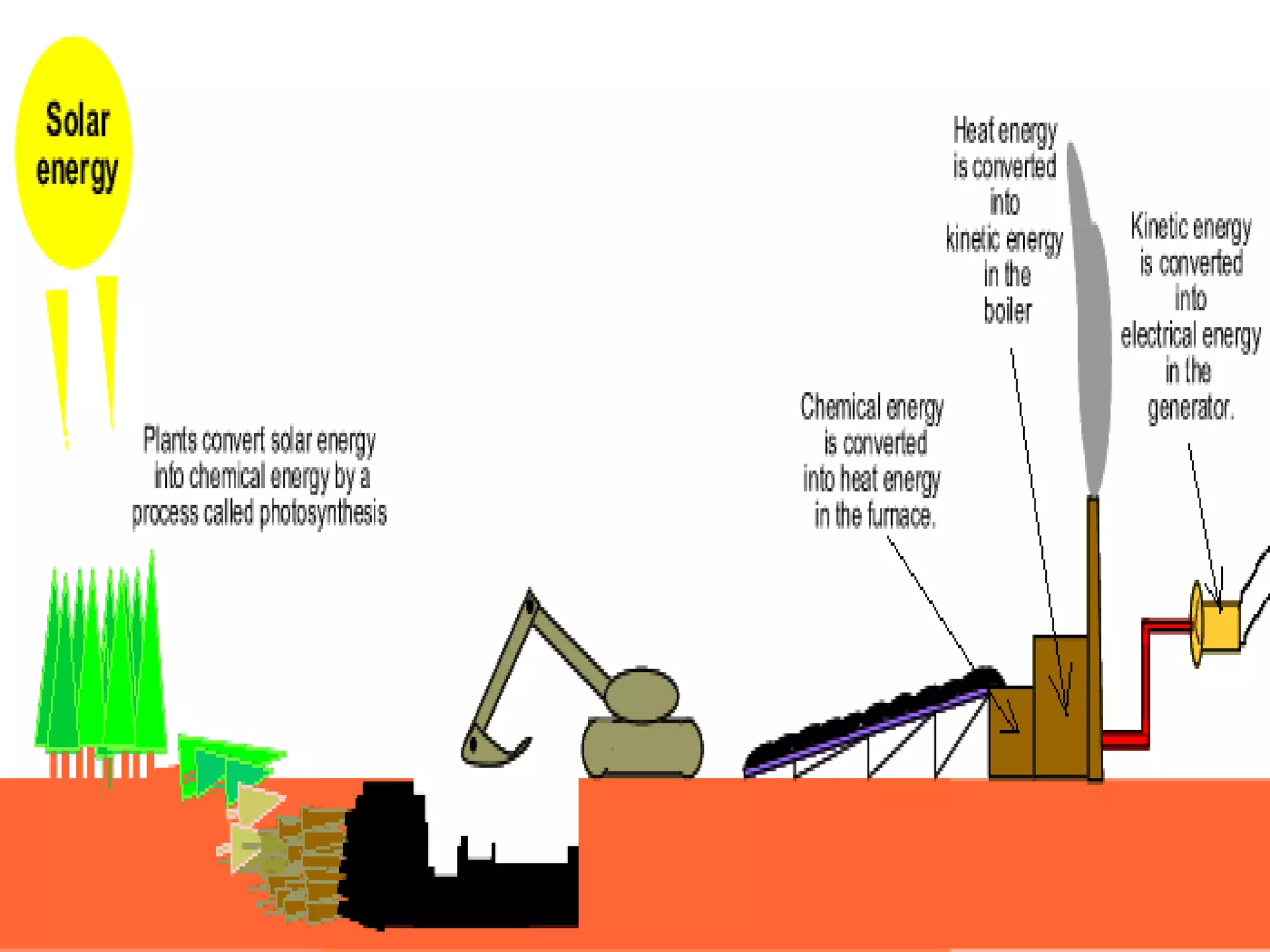
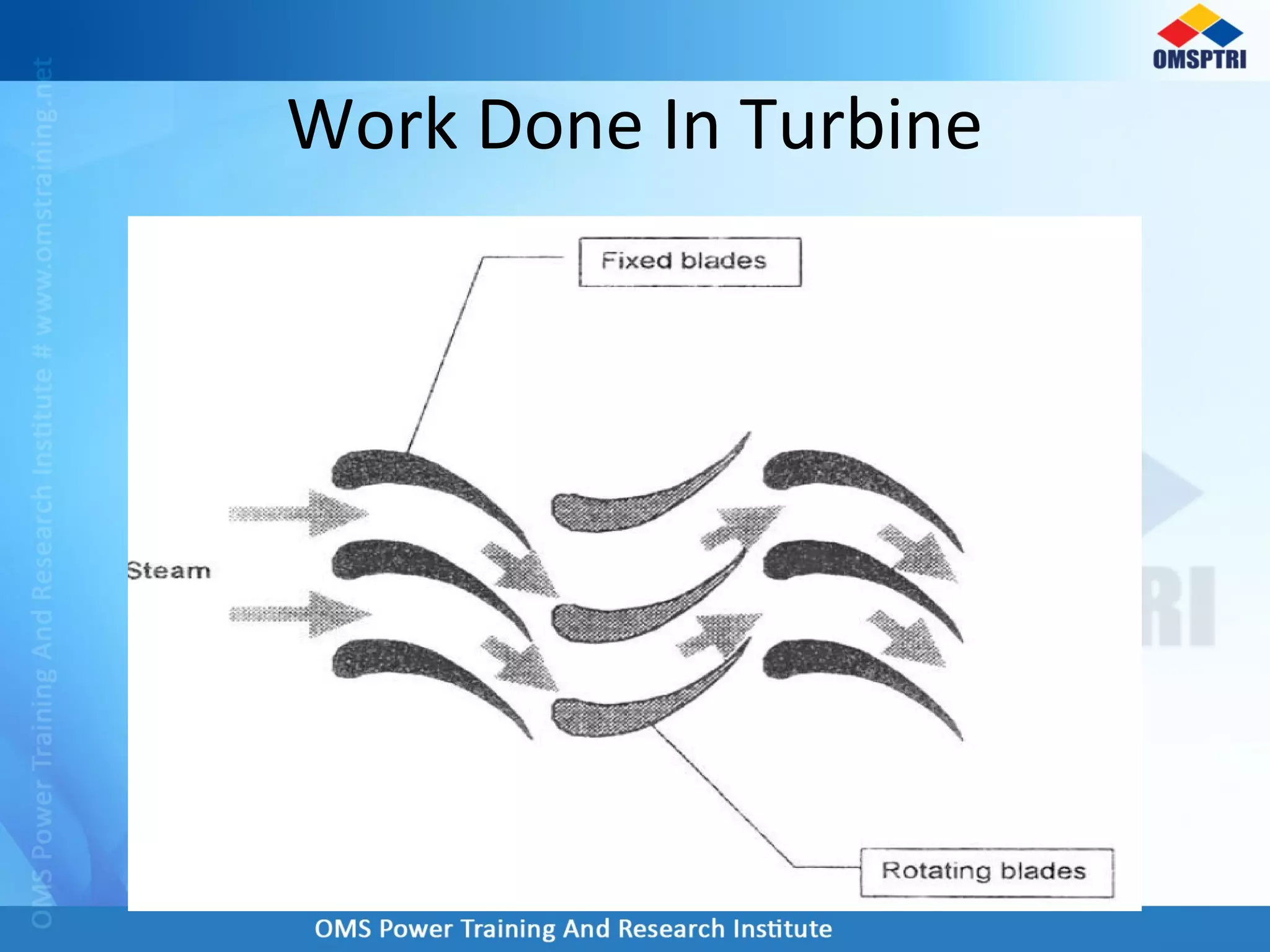
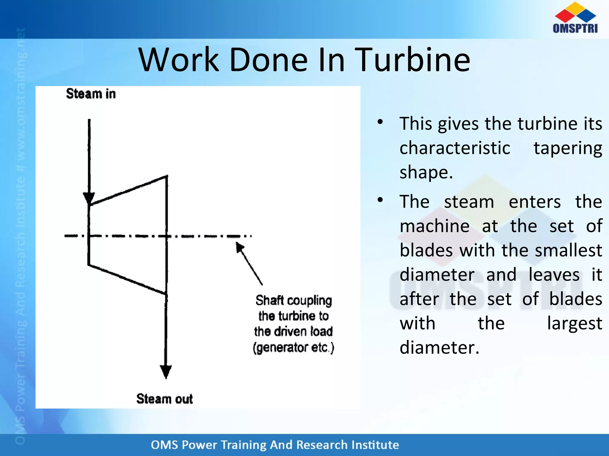


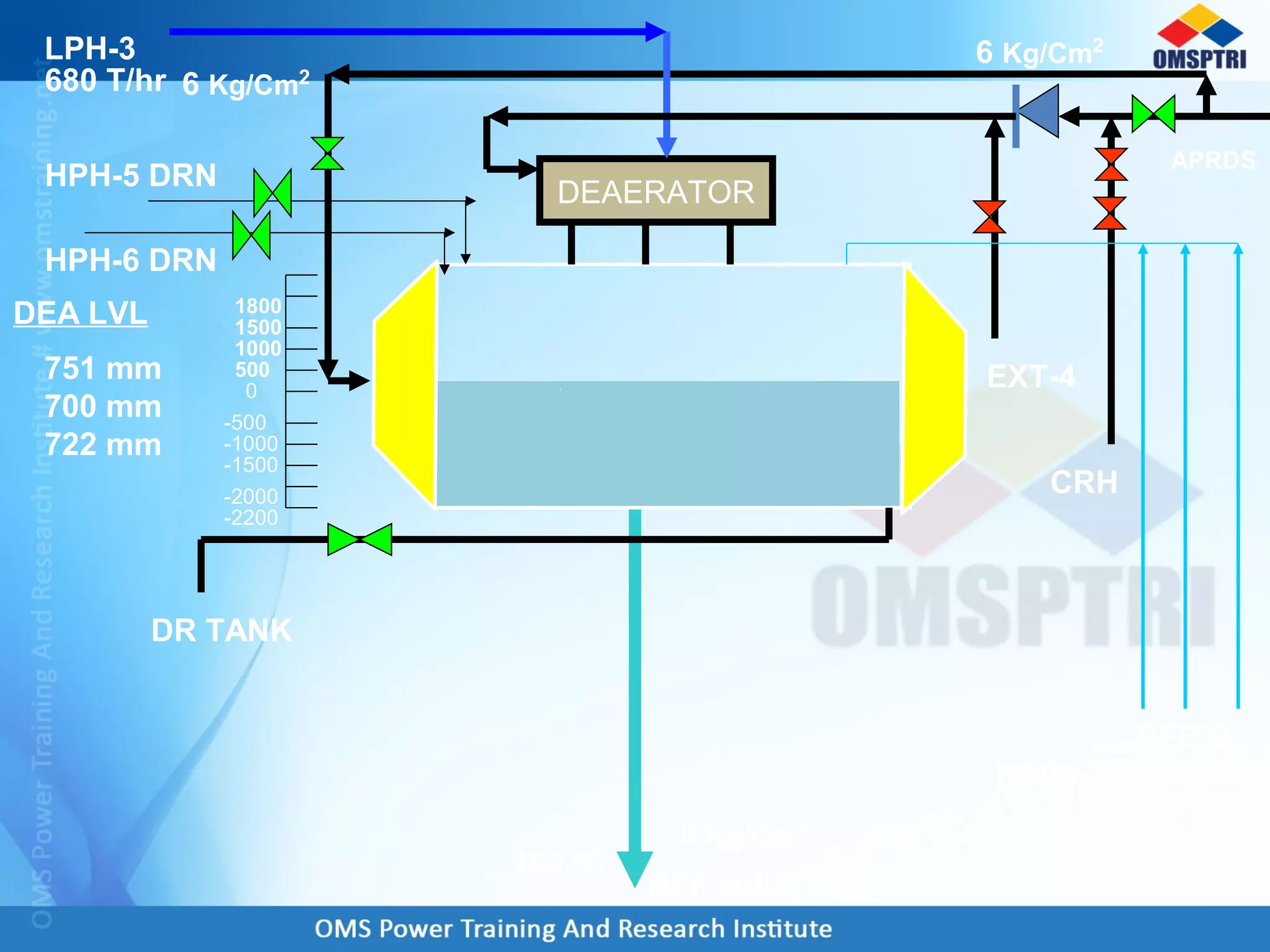


The document discusses how work is done in a turbine. It explains that: 1) The heat energy in steam is converted to kinetic energy as it enters the turbine through nozzles, and then to mechanical work as it impacts the rotating blades. 2) Further work is done as the steam reacts with fixed blades, redirecting it to more rotating blades. 3) As the steam travels through the machine, it continually expands, giving up energy at each set of blades. 4) The tapering shape of the turbine allows the steam to enter at smaller blades and exit at larger blades.