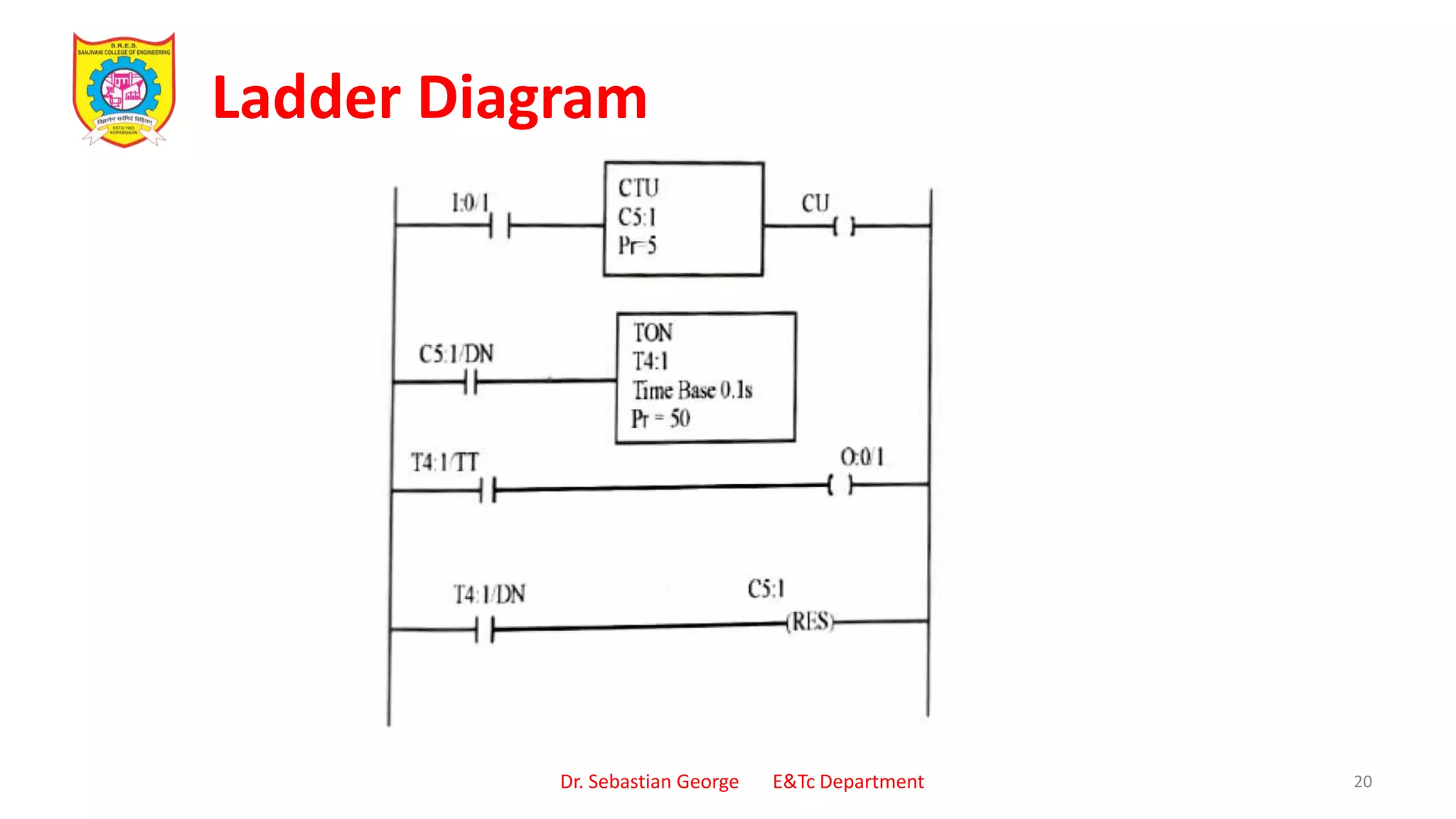
1) The document provides examples of ladder logic diagrams for various industrial automation processes and systems, as presented by Dr. Sebastian George to students in a PLCs and Industrial Automation course.
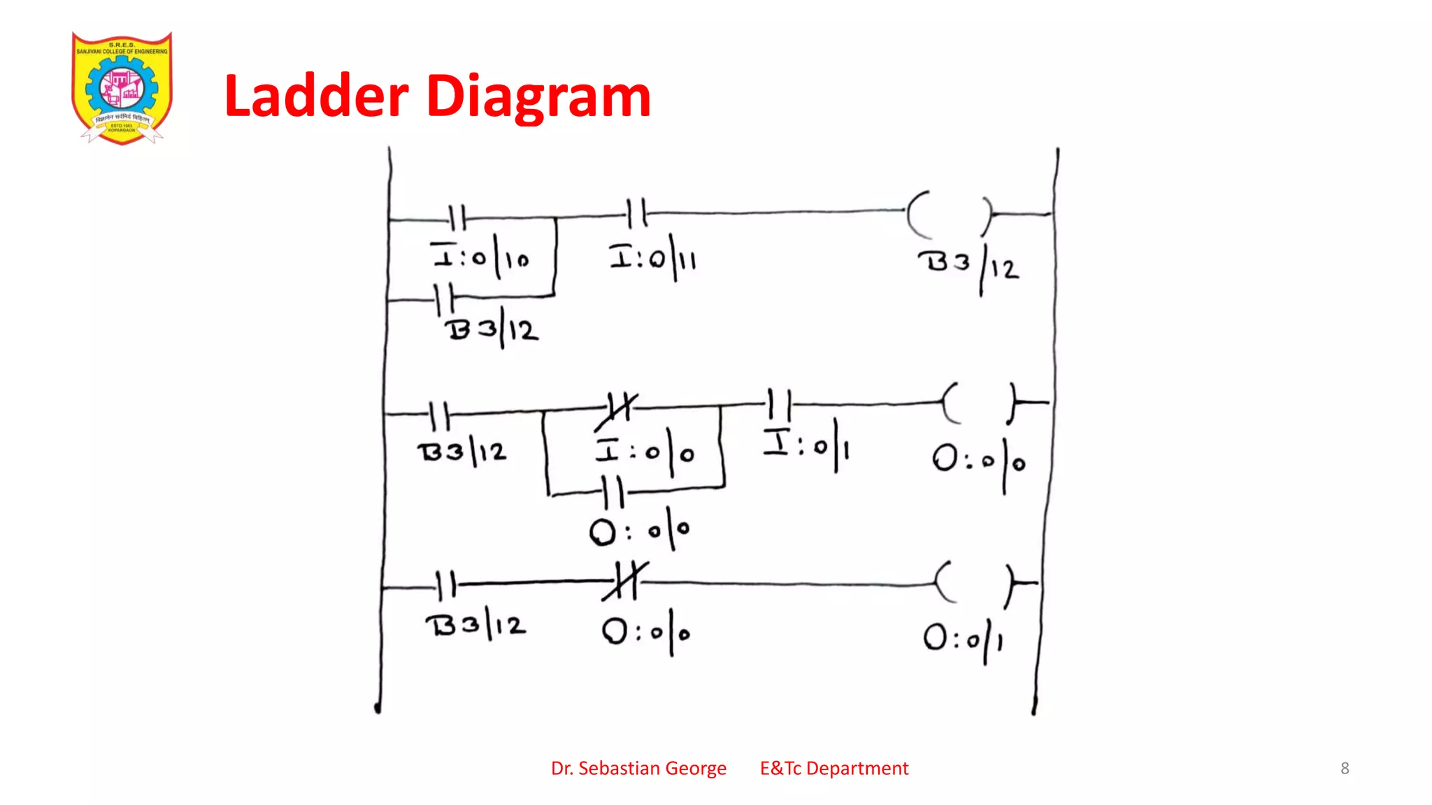
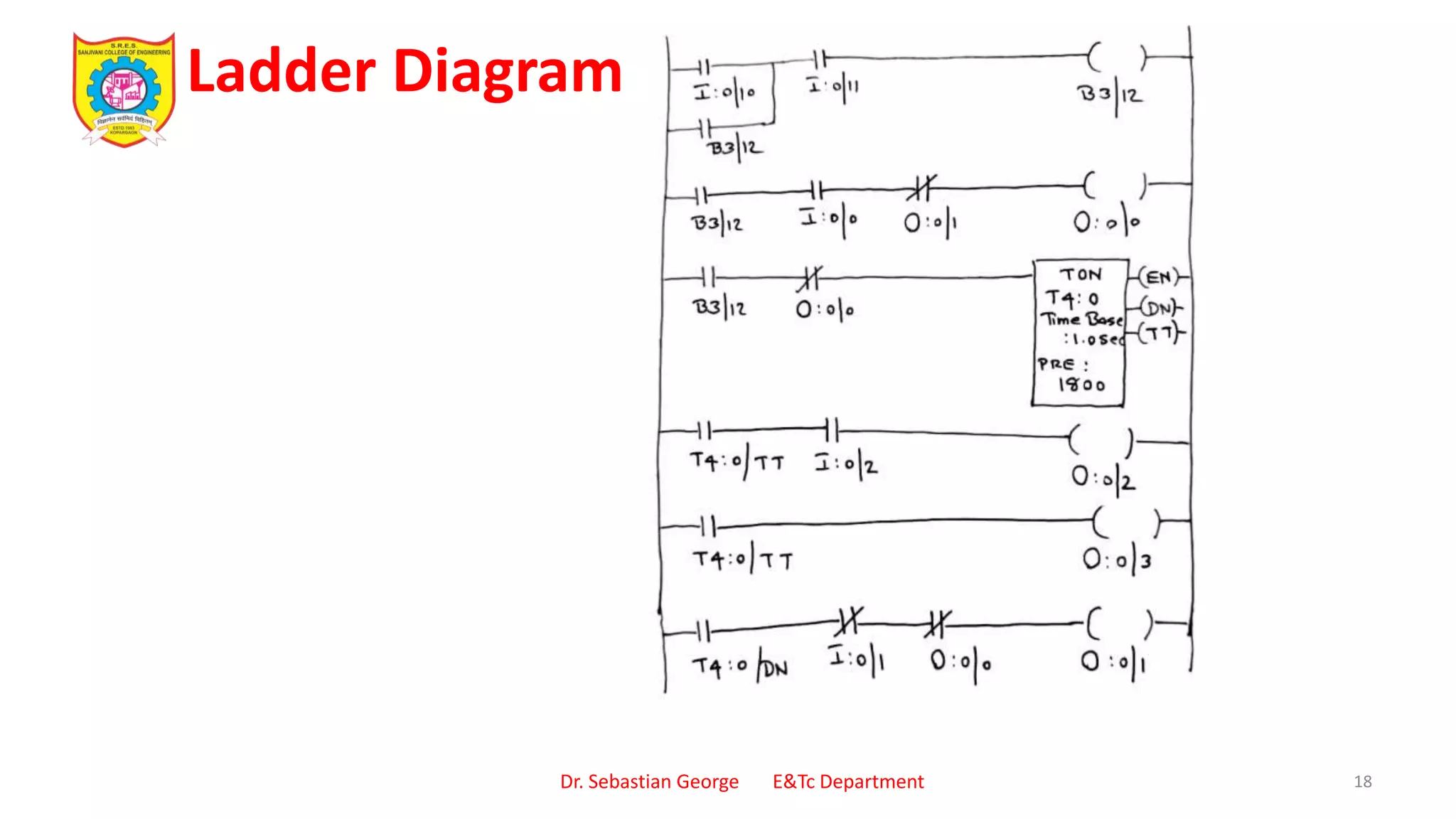
2) Six examples are given of ladder logic diagrams that control motors, heating and stirring processes, and a box packaging system based on inputs like push buttons, limit switches, and temperature sensors.
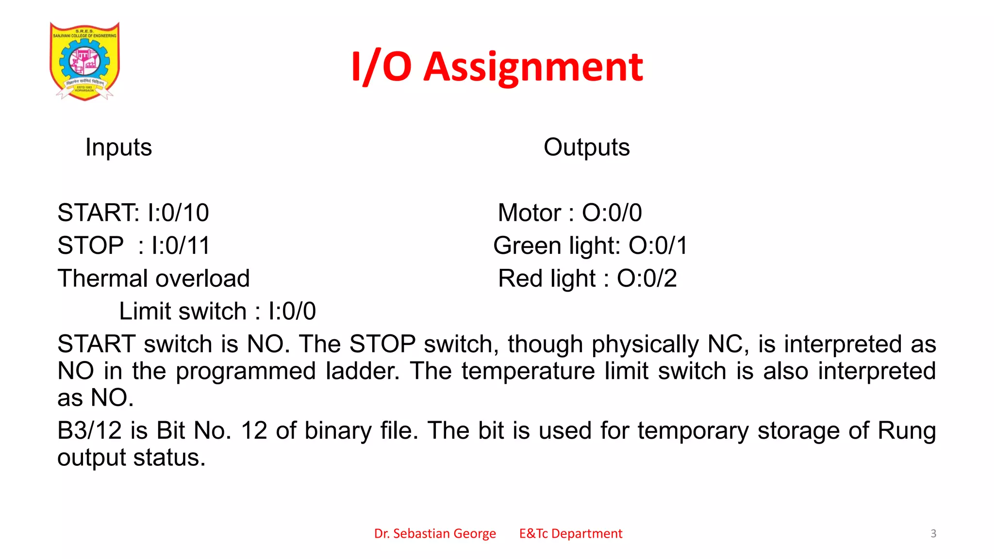
3) For each example, the inputs, outputs, and purpose of the automation process are described, and the corresponding ladder logic diagram is displayed and explained.