Chapter 1. Introduction
toControl System
Instructor: Engr. Dale Mark N. Bristol
Department of Mechanical Engineering
2.
What is ControlEngineering?
Control Engineering is concerned with techniques that are used to
solve the following six problems in the most efficient manner
possible.
(a)The identification problem: to measure the variables and
convert data for analysis.
(b)The representation problem: to describe a system by an
analytical form or mathematical model.
(c)The solution problem: to determine the above system model
response.
(d)The stability problem: general qualitative analysis of the system
(e)The design problem: modification of an existing system or
development of a new one.
3.
What is ControlEngineering?
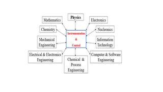
Therefore, control engineering is not limited to any engineering
discipline but is equally applicable to aeronautical, chemical,
mechanical, environmental, civil and electrical engineering.
For example, a control system often includes electrical,
mechanical and chemical components.
Furthermore, as the understanding of the dynamics of business,
social and political systems increases; the ability to control these
systems will also increase.
5.
What is aControl System?
A control system can be thought of as a system which can be
used to:
control some variable to some particular value, e.g. a central
heating system where the temperature is controlled to a
particular value;
control the sequence of events, e.g. a washing machine
where when the dials are set to, say, ‘white’ and the machine
is then controlled to a particular washing cycle, i.e. sequence
of events, appropriate to that type of clothing;
control whether an event occurs or not, i.e. a safety lock on
a machine where it cannot be operated until a guard is in
position.
6.
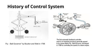
History of ControlSystem
Fly – Ball Governor” by Boulton and Watt in 1798
7.
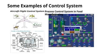
Some Examples ofControl System
Process Control System in Food
Manufacturing
8.
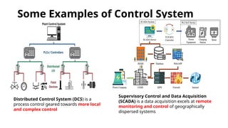
Some Examples ofControl System
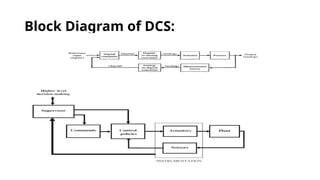
Distributed Control System (DCS) is a
process control geared towards more local
and complex control
Supervisory Control and Data Acquisition
(SCADA) is a data acquisition excels at remote
monitoring and control of geographically
dispersed systems
9.
Fact or Myth
1.When choosing to change out or upgrade your building
controls system, you have to stick with a proprietary vendor.
2. Building automation systems require a large in-house
support team and drive up operating costs.
3. A control system doesn’t require regular maintenance for
optimal performance.
4. Access control systems are only for large installations.
5. Access control systems can't be integrated with other
security systems.
Answer: ALL are Myths or Bluff
10.
Classification of ControlSystems
Open Loop Control System
Closed Loop Control System
Linear Control System
Nonlinear Control Systems
Time Variant Control System
Time Invariant Control System
Continuous-time and Discrete-time Control Systems
Feedforward Control System
Digital Control System
11.
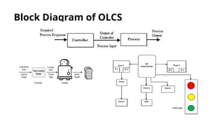
1. Open LoopControl Systems
Open-loop control systems, also known as non-feedback
systems, function without thinking about the machine's output.
In this setup, the controller sends commands to the system, and
the device responds without any feedback mechanism.
While open-loop structures are simple and value-effective, they
lack the potential to adapt to changes or disturbances within the
system, making them less suitable for applications requiring
precision and reliability.
Features of open-loop control systems include direct coupling
between input and output, no feedback mechanism, and simple
and price-powerful.
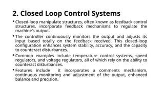
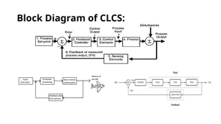
2. Closed LoopControl Systems
Closed-loop manipulate structures, often known as feedback control
structures, incorporate feedback mechanisms to regulate the
machine's output.
The controller continuously monitors the output and adjusts its
input based totally on the feedback received. This closed-loop
configuration enhances system stability, accuracy, and the capacity
to counteract disturbances.
Common examples include temperature control systems, speed
regulators, and voltage regulators, all of which rely on the ability to
counteract disturbances.
Features include it incorporates a comments mechanism,
continuous monitoring and adjustment of the output, enhanced
balance and precision.
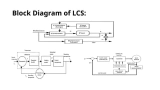
3. Linear ControlSystems
Linear control systems exhibit a linear relationship
between the input and output variables.
The principle of superposition holds, meaning that the
machine's reaction to a sum of multiple inputs is equal to
the sum of the individual responses.
Linear control systems are mathematically tractable,
facilitating analysis and design. They discover substantial
utility in various digital gadgets and systems.
Features include exhibiting a linear coupling between
input and output, employing the principle of
superposition, and being mathematically tractable.
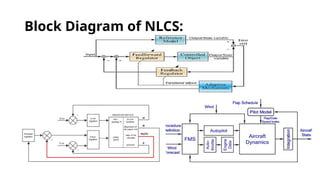
5. Non LinearControl Systems
Nonlinear control systems contain nonlinear relationships
between input and output.
The behavior of these systems is extra complicated, and
frequently nonlinear equations govern their dynamics.
Nonlinear control systems are encountered in programs in
which linear approximations are insufficient, along with
enormously dynamic systems, chaotic systems, with massive
nonlinearity.
Features include involvement of nonlinear relationships
between enter and output, applicability to complex and
dynamic systems and may require advanced mathematical
equipment for analysis.
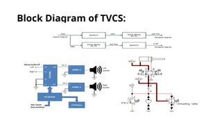
6. Time Variantand Time Varying Control Systems
Time-invariant control systems hold steady characteristics
over the years.
The parameters governing the machine's conduct continue
to be unchanged. Conversely, time-varying manipulated
structures experience versions of their parameters over time.
Time-varying systems are commonplace in packages in
which the device's dynamics change due to external factors,
making adaptability an essential requirement.
Features include time-invariant structures that preserve
regular traits and time-varying structures that experience
parameter variations over time.
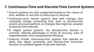
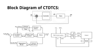
7. Continuous-Time andDiscrete-Time Control Systems
Control systems are also categorized based on the nature of
time, whether or not time is continuous or discrete.
Continuous-time control systems deal with changes that
constantly change concerning time, even as discrete-time
control structures perform on changes that might be sampled
at discrete time intervals.
In digital control systems, the discrete-time domain is
common, offering advantages in terms of accuracy, ease of
implementation, and computational efficiency.
Features include continuous-time systems that operate on
alerts that adjust constantly, and discrete-time structures
function on sampled signals at discrete intervals.
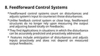
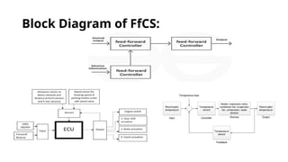
8. Feedforward ControlSystems
Feedforward control systems count on disturbances and
adjusts system's input to counteract those disturbances.
Unlike feedback control system or close loop, feedforward
structures do no longer rely upon measuring the output
and adjusting based totally on Feedbacks.
They find Applications in situations in which the disturbance
can be accurately predicted and proactively addressed.
Features include anticipation of disturbances and adjusts
inputs proactively and does not depend on measured
output feedbacks.
9. Digital ControlSystems
Digital control systems contain using virtual computers or
processors to manage algorithms.
These systems offer precise manipulate, ease of
implementation, and the capability to address complex
algorithms.
Digital manipulate structures are customary in modern
electronics engineering, locating packages in robotics,
commercial automation, and utilized in various advanced
control applications.
Features include employing digital computer systems or
processors and implementation of control algorithms
digitally.
Basic Elements ofa Closed-Loop System
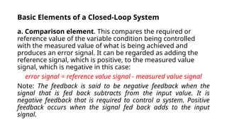
a. Comparison element. This compares the required or
reference value of the variable condition being controlled
with the measured value of what is being achieved and
produces an error signal. It can be regarded as adding the
reference signal, which is positive, to the measured value
signal, which is negative in this case:
error signal = reference value signal - measured value signal
Note: The feedback is said to be negative feedback when the
signal that is fed back subtracts from the input value. It is
negative feedback that is required to control a system. Positive
feedback occurs when the signal fed back adds to the input
signal.
28.
Basic Elements ofa Closed-Loop System
b. Control element. This decides what action to take when it
receives an error signal. It may be, for example, a signal to
operate a switch or open a valve. The control plan being used
by the element may be just to supply a signal which switches
on or off when there is an error, as in a room thermostat, or
perhaps a signal which proportionally opens or closes a valve
according to the size of the error. Control plans may be hard-
wired systems in which the control plan is permanently fixed
by the way the elements are connected, or programmable
systems where the control plan is stored within a memory
unit and may be altered by reprogramming it.
29.
Basic Elements ofa Closed-Loop System
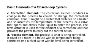
c. Correction element. The correction element produces a
change in the process to correct or change the controlled
condition. Thus, it might be a switch that switches on a heater
and so increases the temperature of the process, or a valve
that opens and allows more liquid to enter the process. The
term actuator is used for the element of a correction unit that
provides the power to carry out the control action.
d. Process element. The process is what is being controlled.
It could be a room in a house with its temperature being
controlled or a tank of water with its level being controlled.
30.
Basic Elements ofa Closed-Loop System
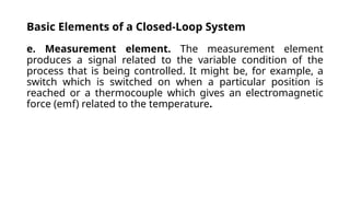
e. Measurement element. The measurement element
produces a signal related to the variable condition of the
process that is being controlled. It might be, for example, a
switch which is switched on when a particular position is
reached or a thermocouple which gives an electromagnetic
force (emf) related to the temperature.
31.
Example 1.
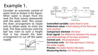
Consider anautomatic control of
water level as shown in the figure.
When water is drawn from the
tank the float moves downwards
with the water level. This causes
the lever arrangement to rotate
and so allows water to enter the
tank. This flow continues until the
ball has risen to such a height
that it has moved the lever
arrangement to cut off the water
supply.
Controlled variable: water level in tank
Reference value: initial setting of the float and
lever position
Comparison element: the lever
Error signal: the difference between the actual
and initial settings of the lever positions
Control unit: the pivoted lever
Correction unit: the flap opening or closing
the water supply
Process: the water level in the tank
Measuring device: the floating ball and lever
32.
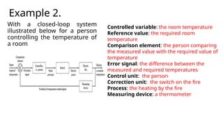
Example 2.
With aclosed-loop system
illustrated below for a person
controlling the temperature of
a room
Controlled variable: the room temperature
Reference value: the required room
temperature
Comparison element: the person comparing
the measured value with the required value of
temperature
Error signal: the difference between the
measured and required temperatures
Control unit: the person
Correction unit: the switch on the fire
Process: the heating by the fire
Measuring device: a thermometer
33.
Homework M- 1.Identify the basic elements in the
closed loop system
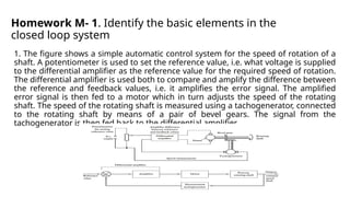
1. The figure shows a simple automatic control system for the speed of rotation of a
shaft. A potentiometer is used to set the reference value, i.e. what voltage is supplied
to the differential amplifier as the reference value for the required speed of rotation.
The differential amplifier is used both to compare and amplify the difference between
the reference and feedback values, i.e. it amplifies the error signal. The amplified
error signal is then fed to a motor which in turn adjusts the speed of the rotating
shaft. The speed of the rotating shaft is measured using a tachogenerator, connected
to the rotating shaft by means of a pair of bevel gears. The signal from the
tachogenerator is then fed back to the differential amplifier.
34.
Homework M- 1.Identify the basic elements in the
closed loop system
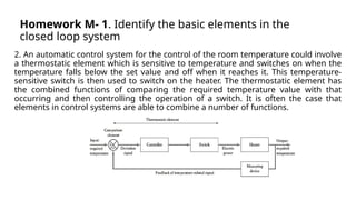
2. An automatic control system for the control of the room temperature could involve
a thermostatic element which is sensitive to temperature and switches on when the
temperature falls below the set value and off when it reaches it. This temperature-
sensitive switch is then used to switch on the heater. The thermostatic element has
the combined functions of comparing the required temperature value with that
occurring and then controlling the operation of a switch. It is often the case that
elements in control systems are able to combine a number of functions.