Downloaded 359 times


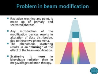
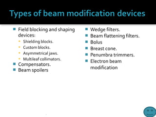


Beam modification devices are used to alter the spatial distribution of radiation within a patient. The main types are shielding, compensation, wedge filtration, and flattening. Shielding blocks parts of the beam to protect tissues, compensation adjusts for tissue heterogeneity, wedge filtration produces tilted isodose curves, and flattening adjusts the natural beam profile. Materials used for beam modification include lead blocks, Cerrobend custom blocks, wedges, and multileaf collimators. Proper selection and design of these devices is needed to modify the beam as desired while minimizing transmission and penumbra effects.


