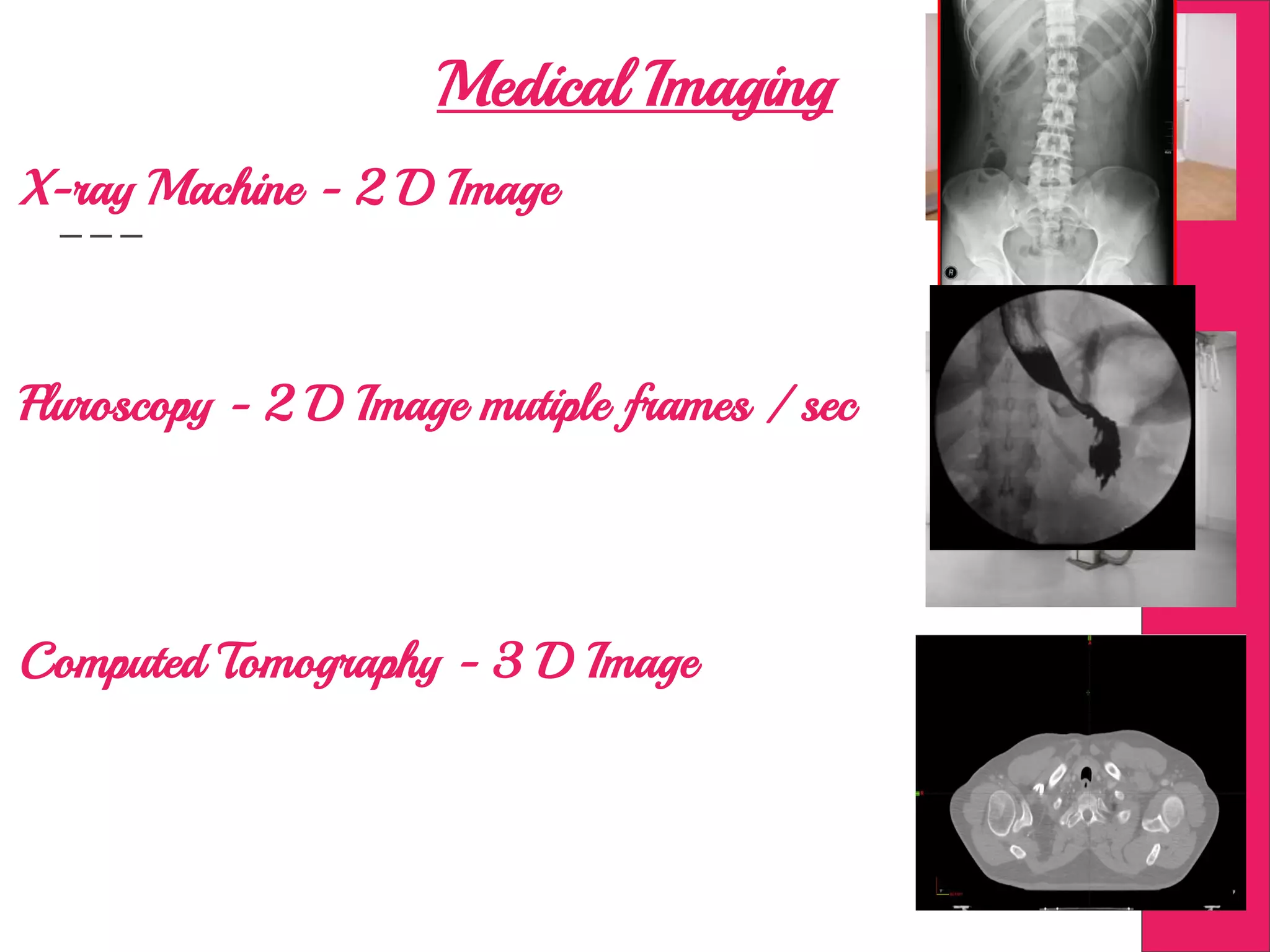
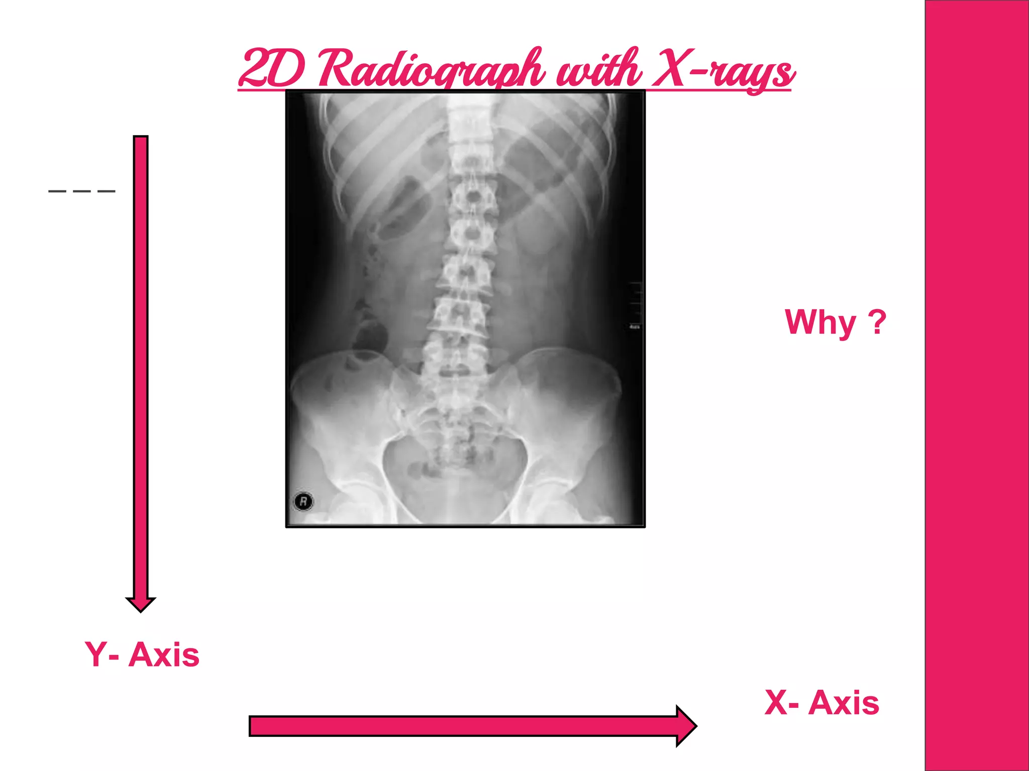
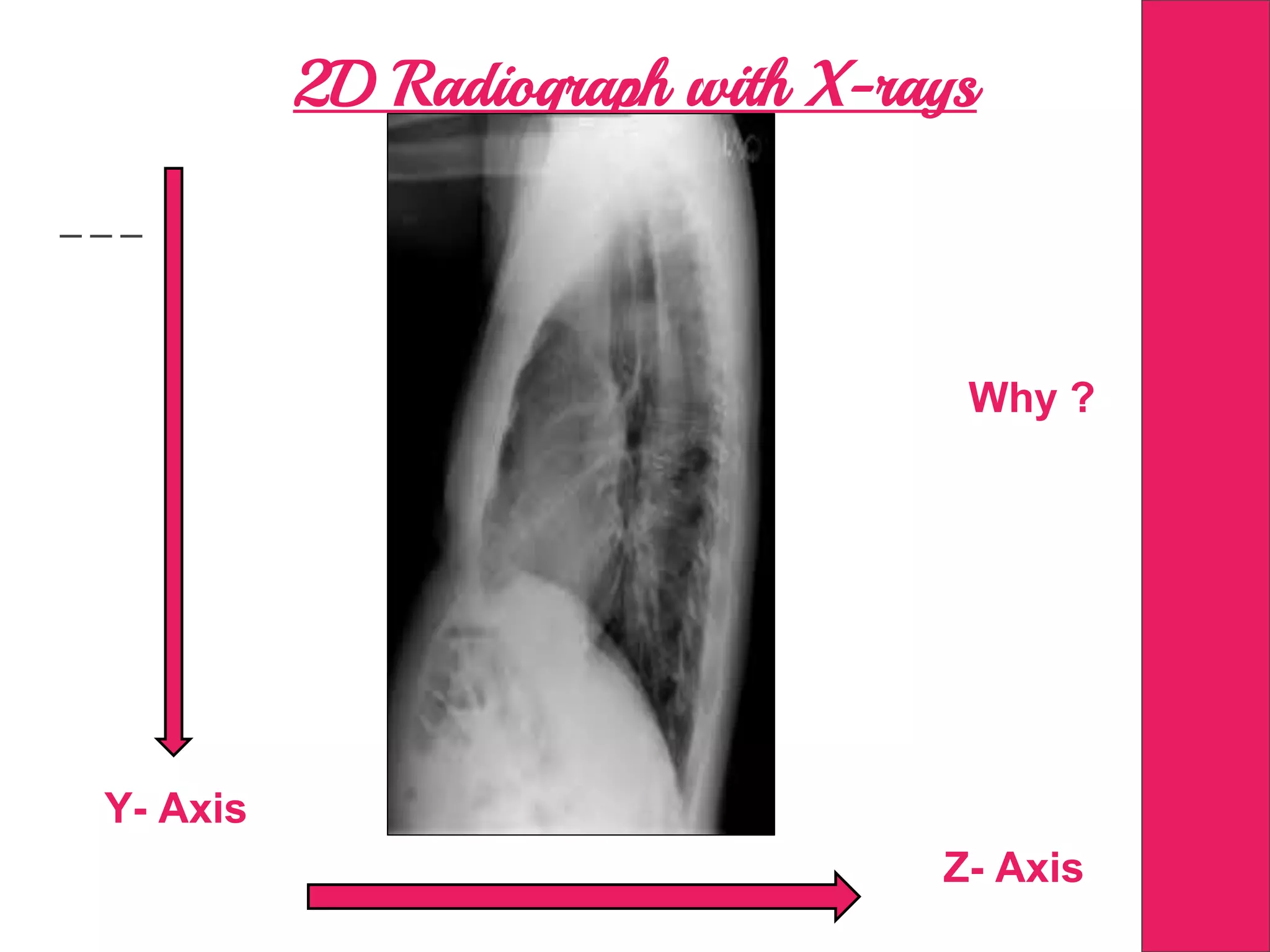
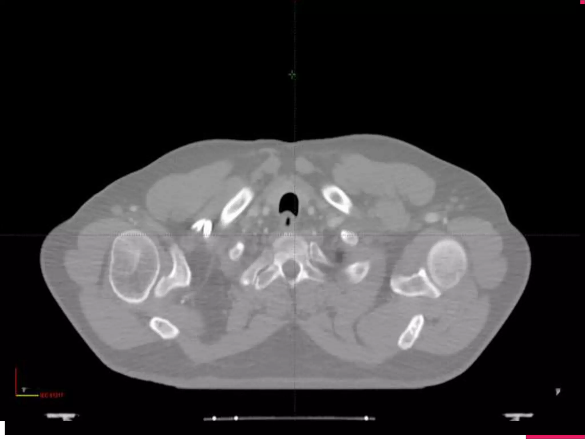
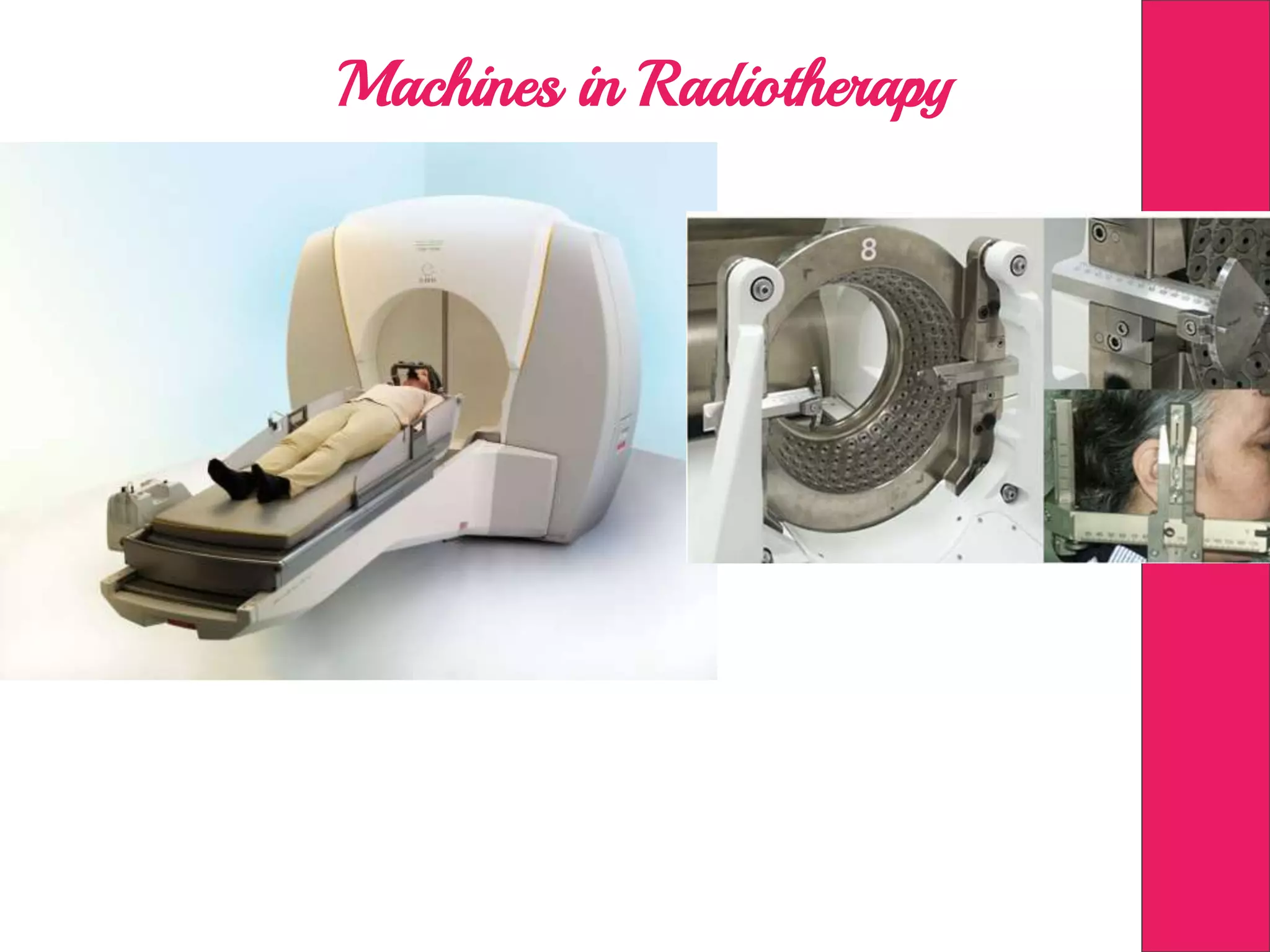
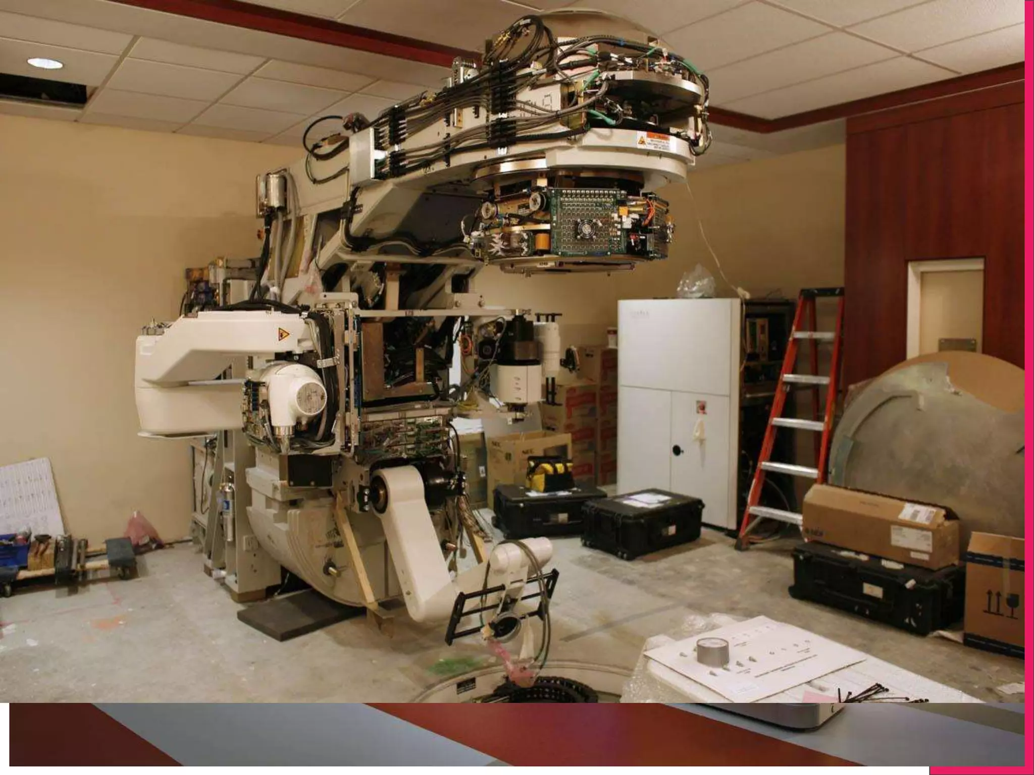
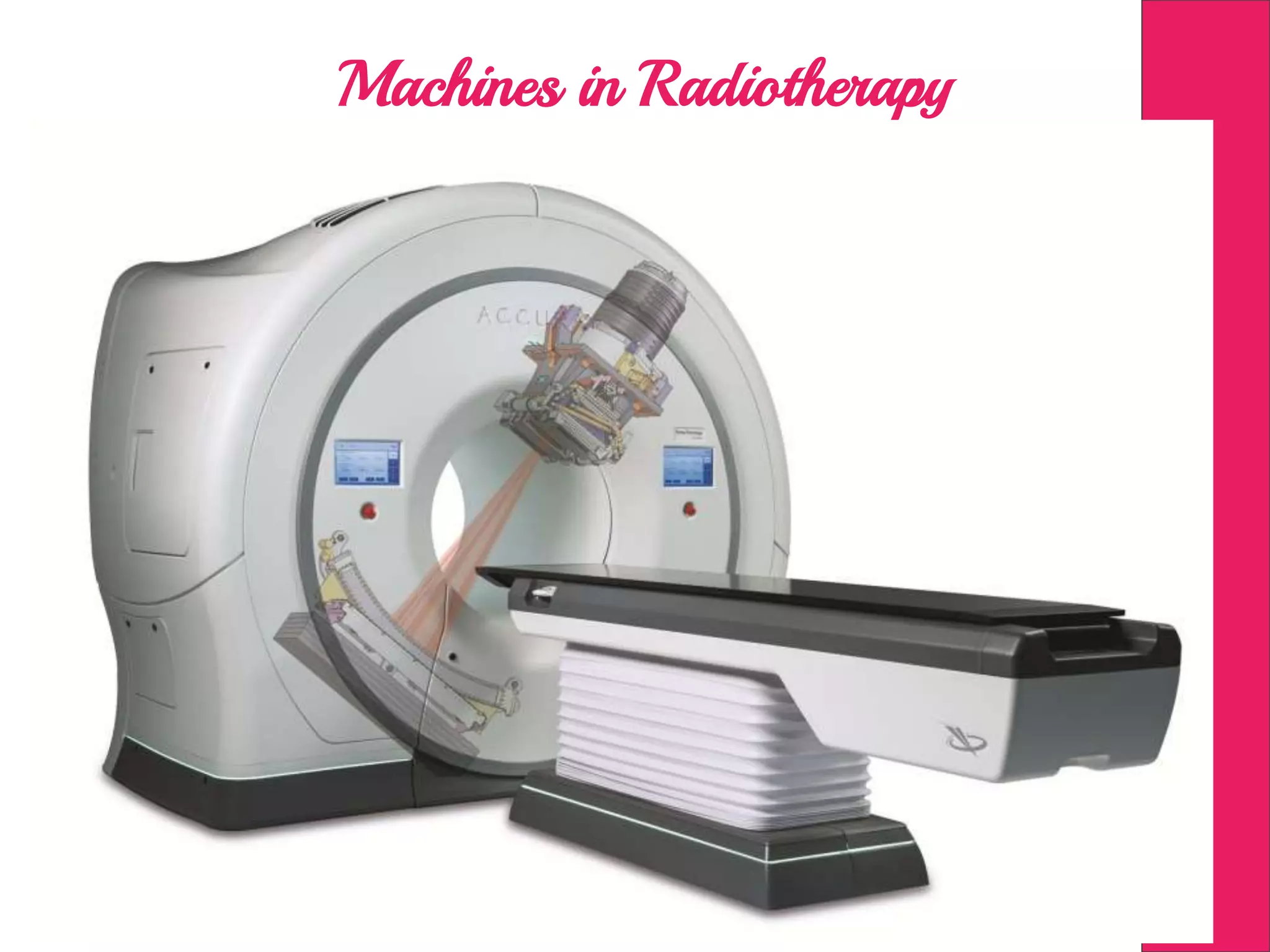
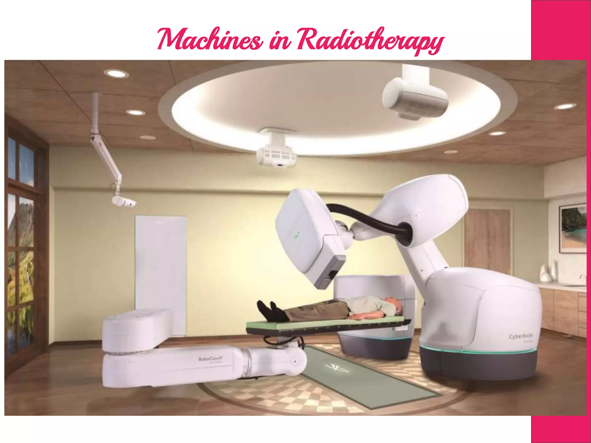
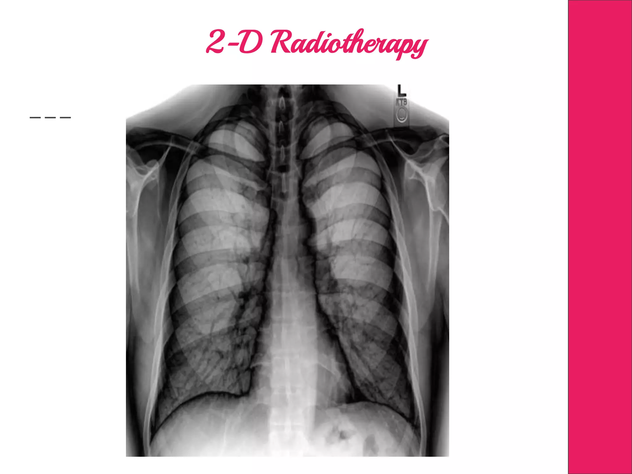
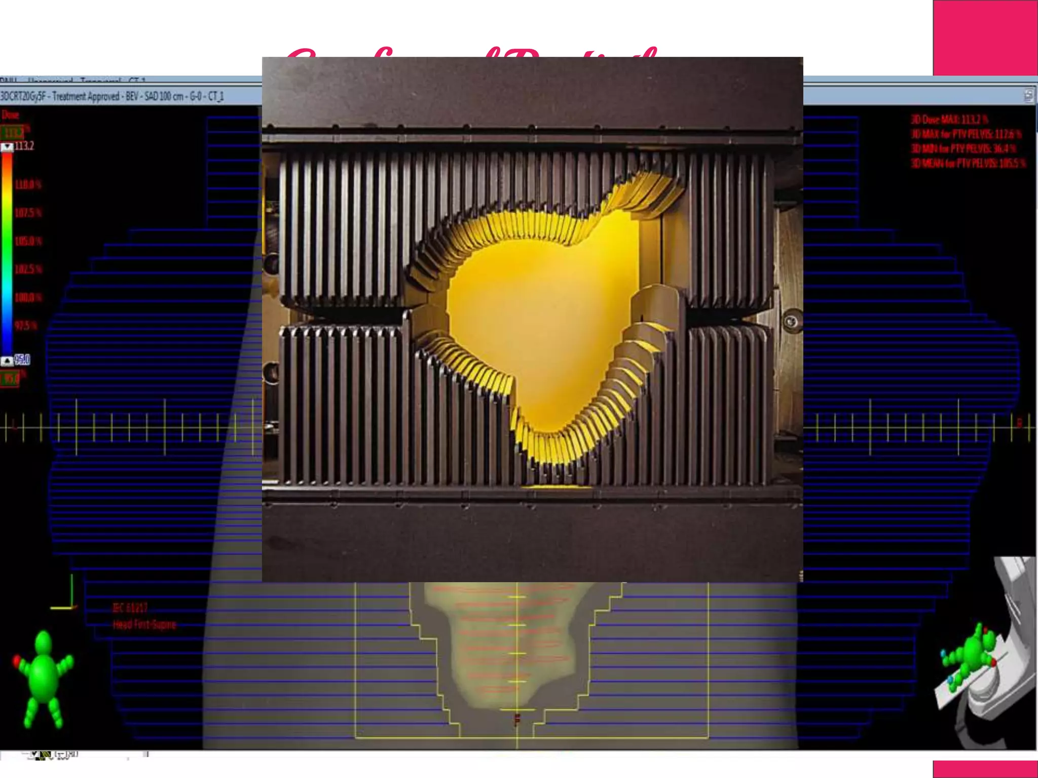
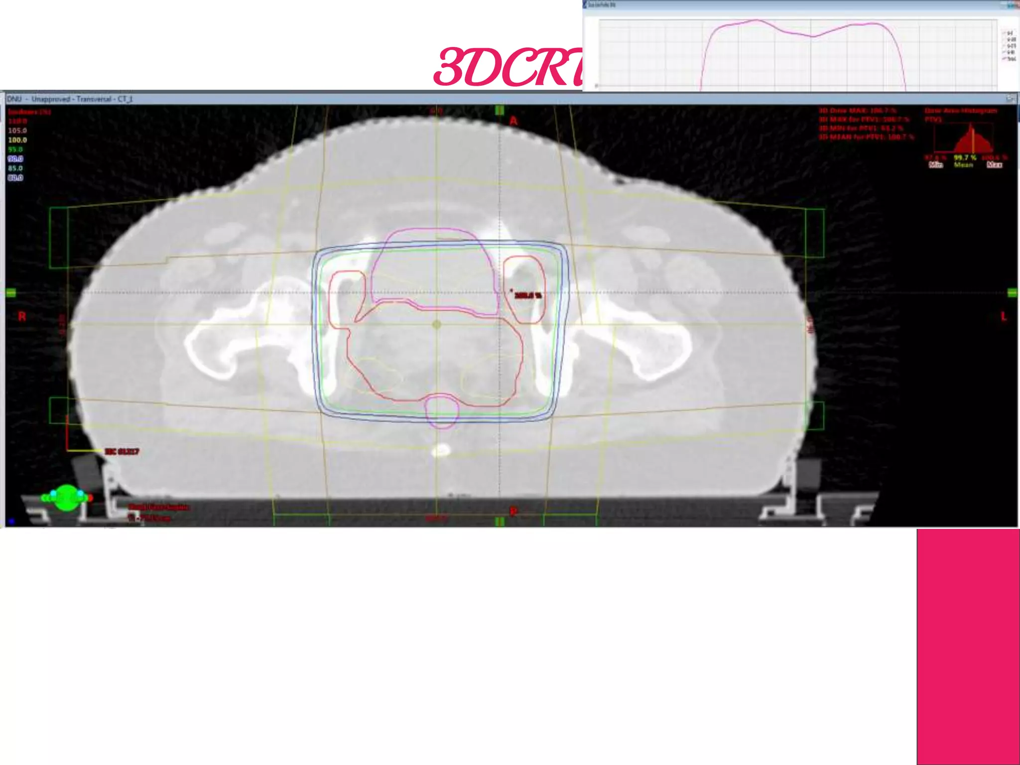
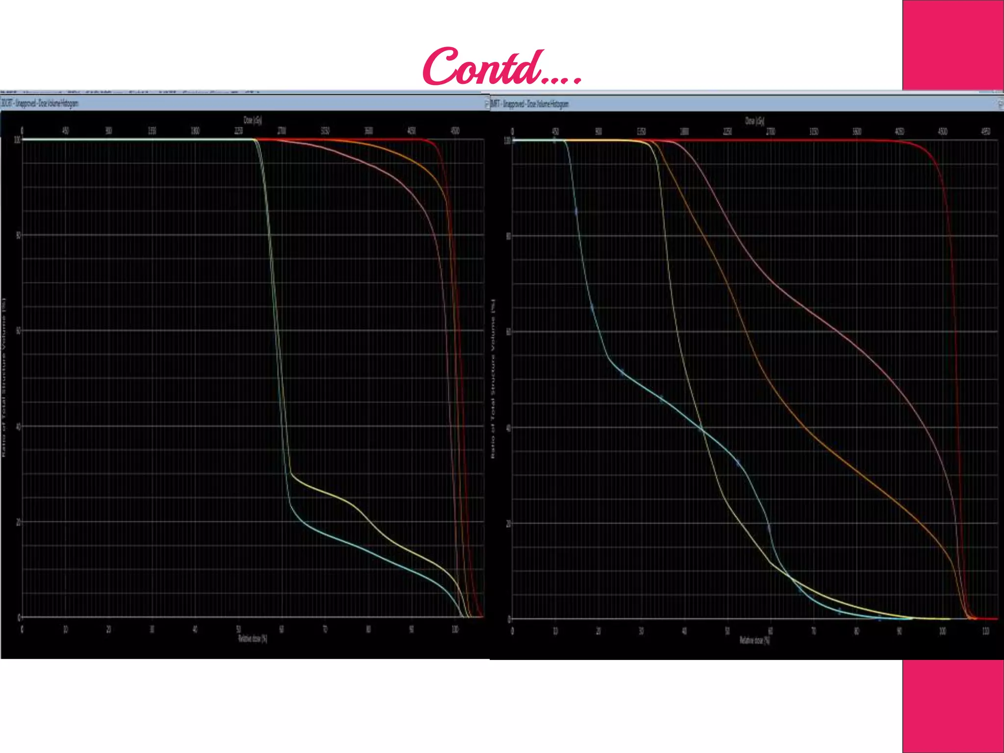
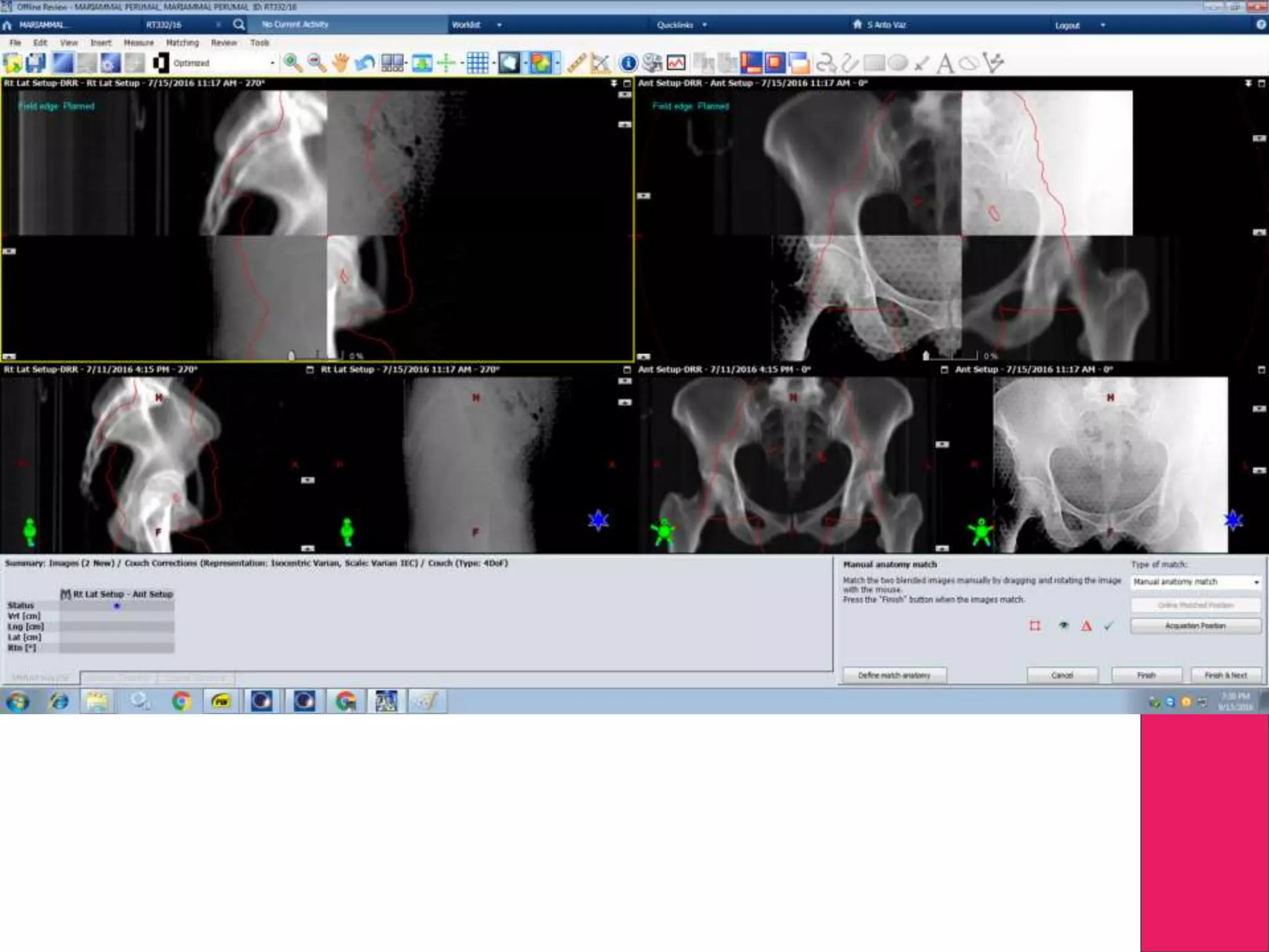
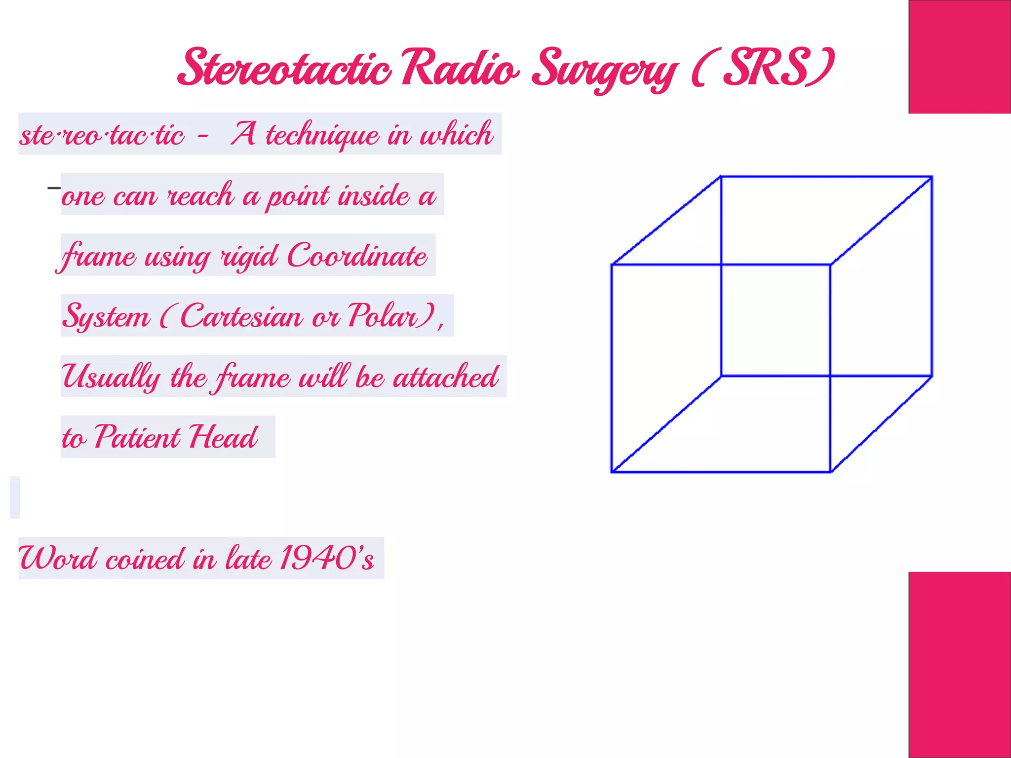
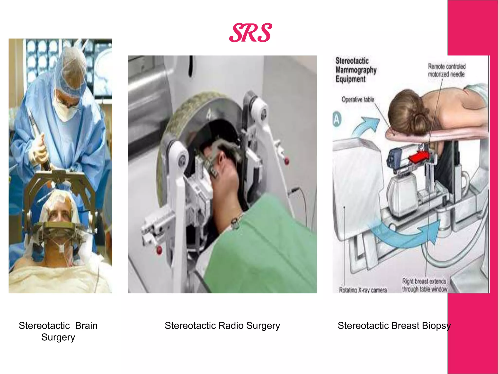
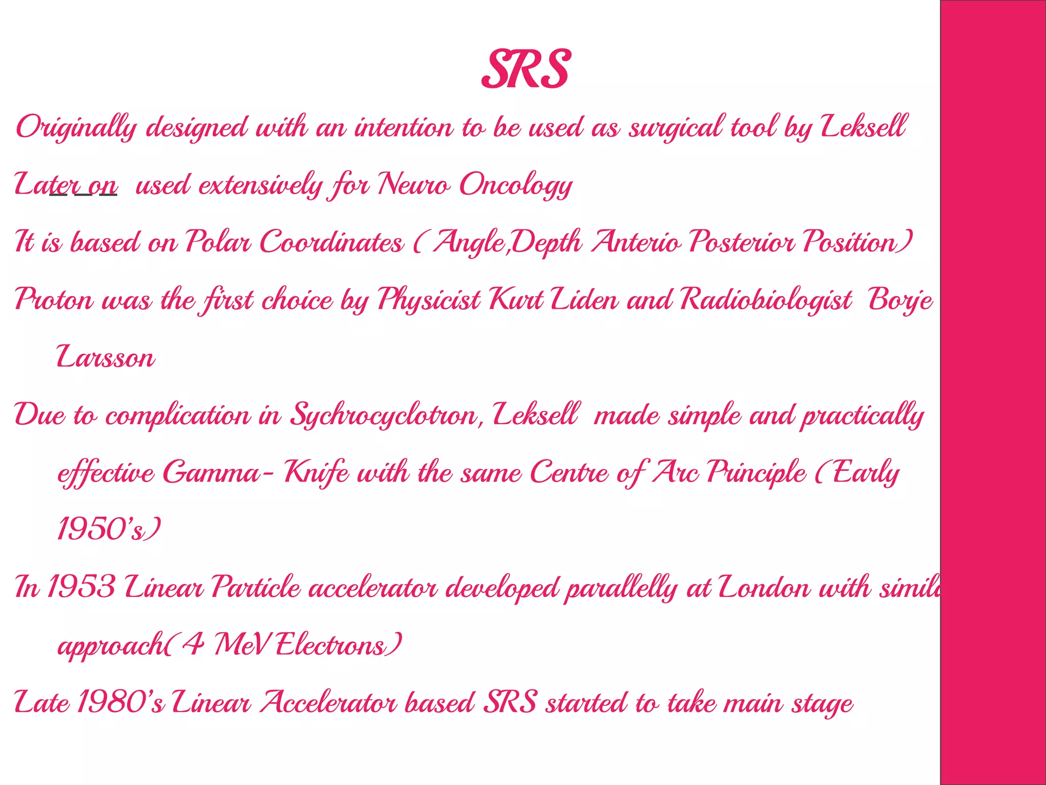
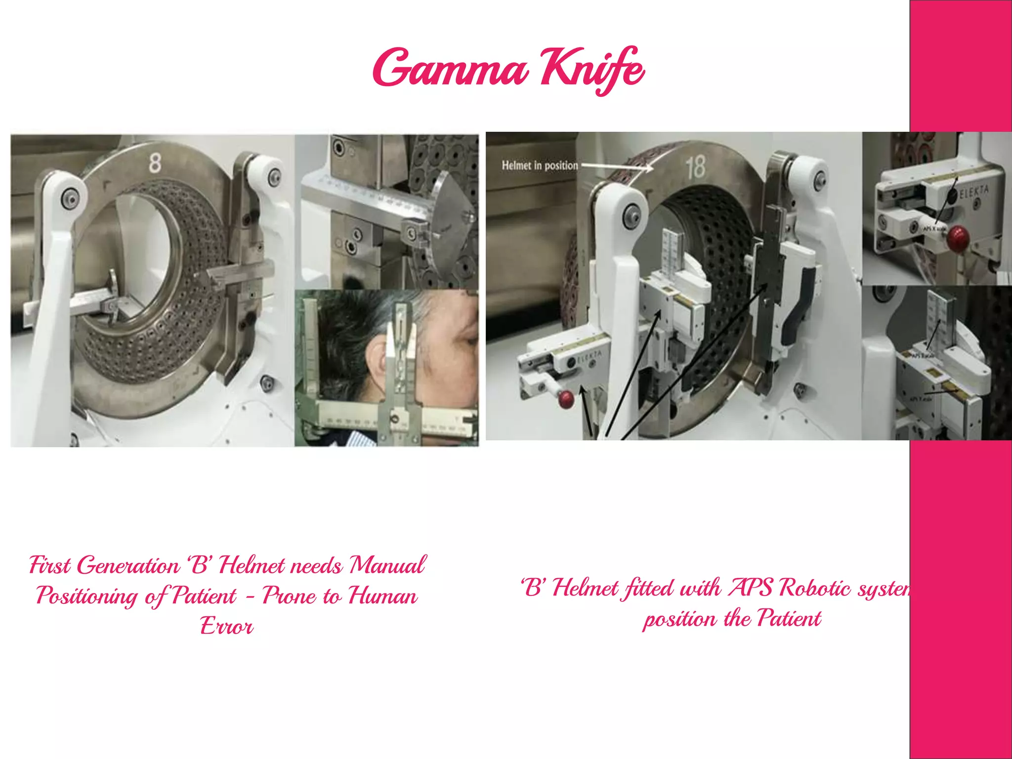
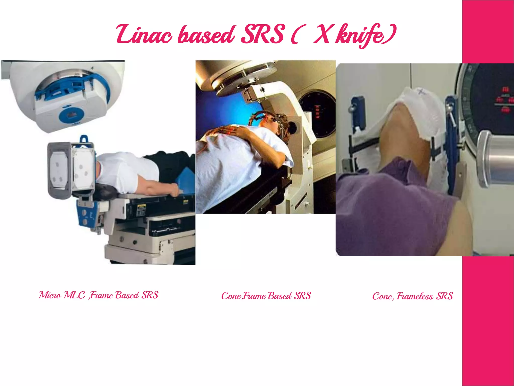
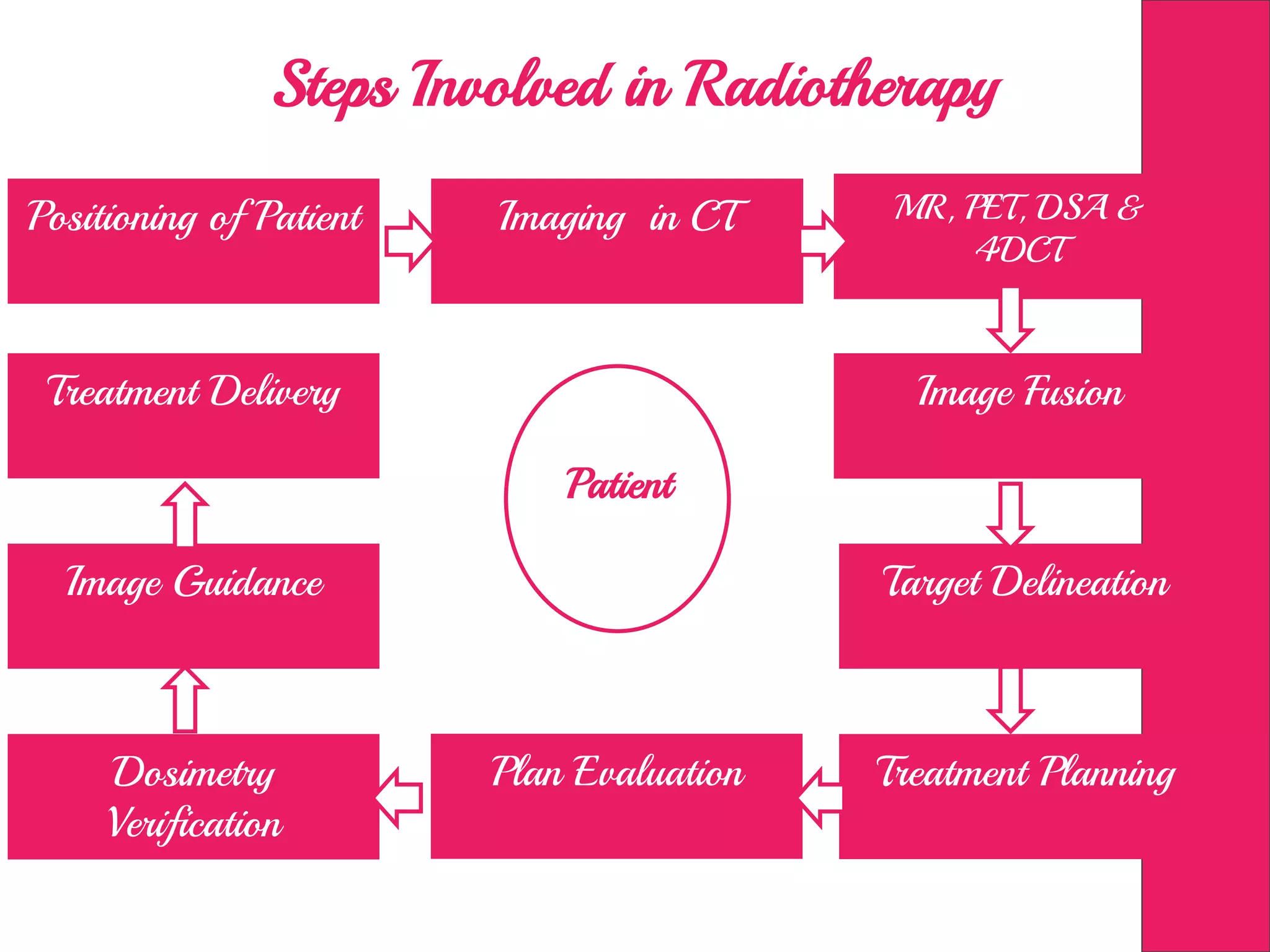
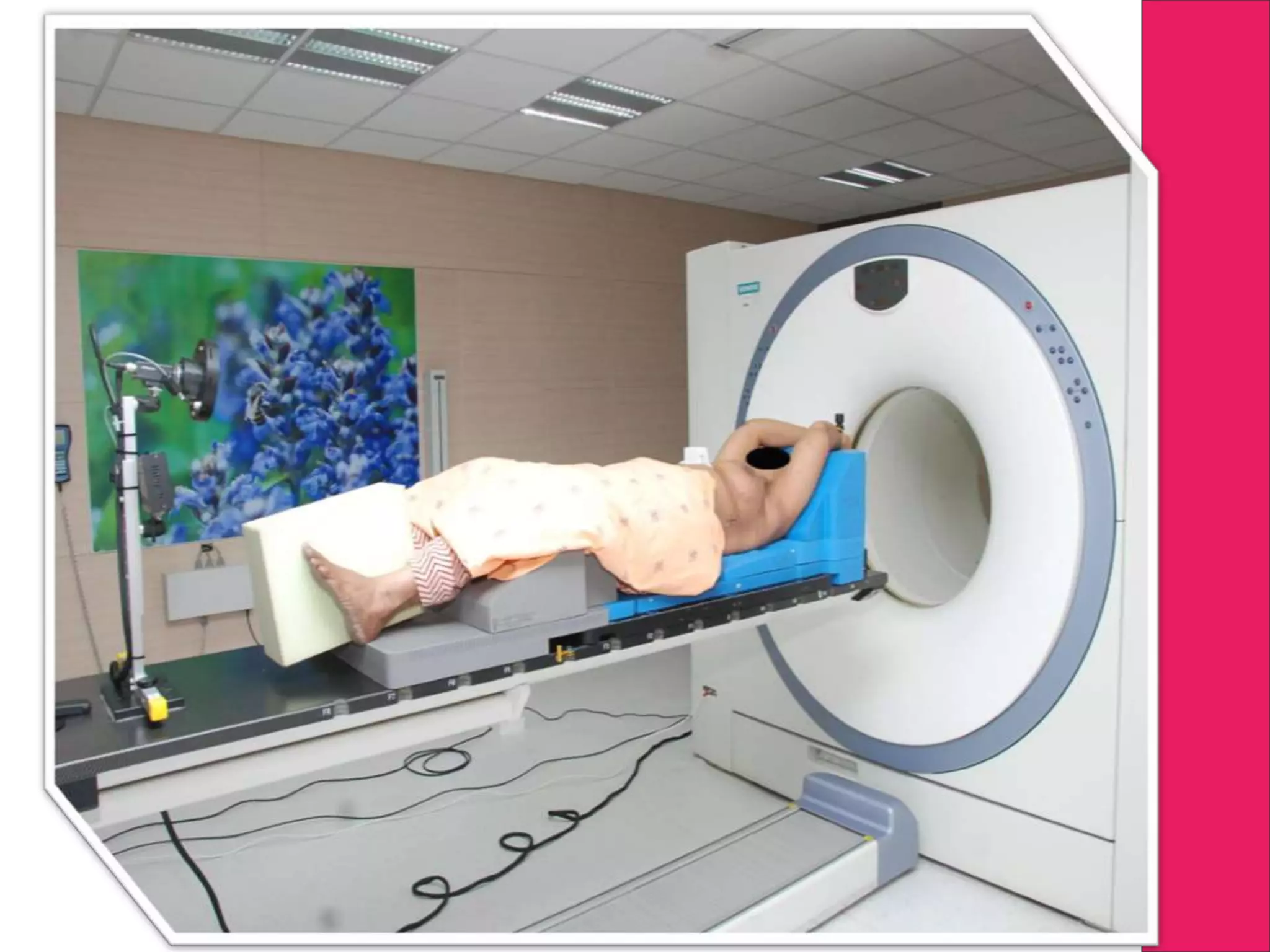
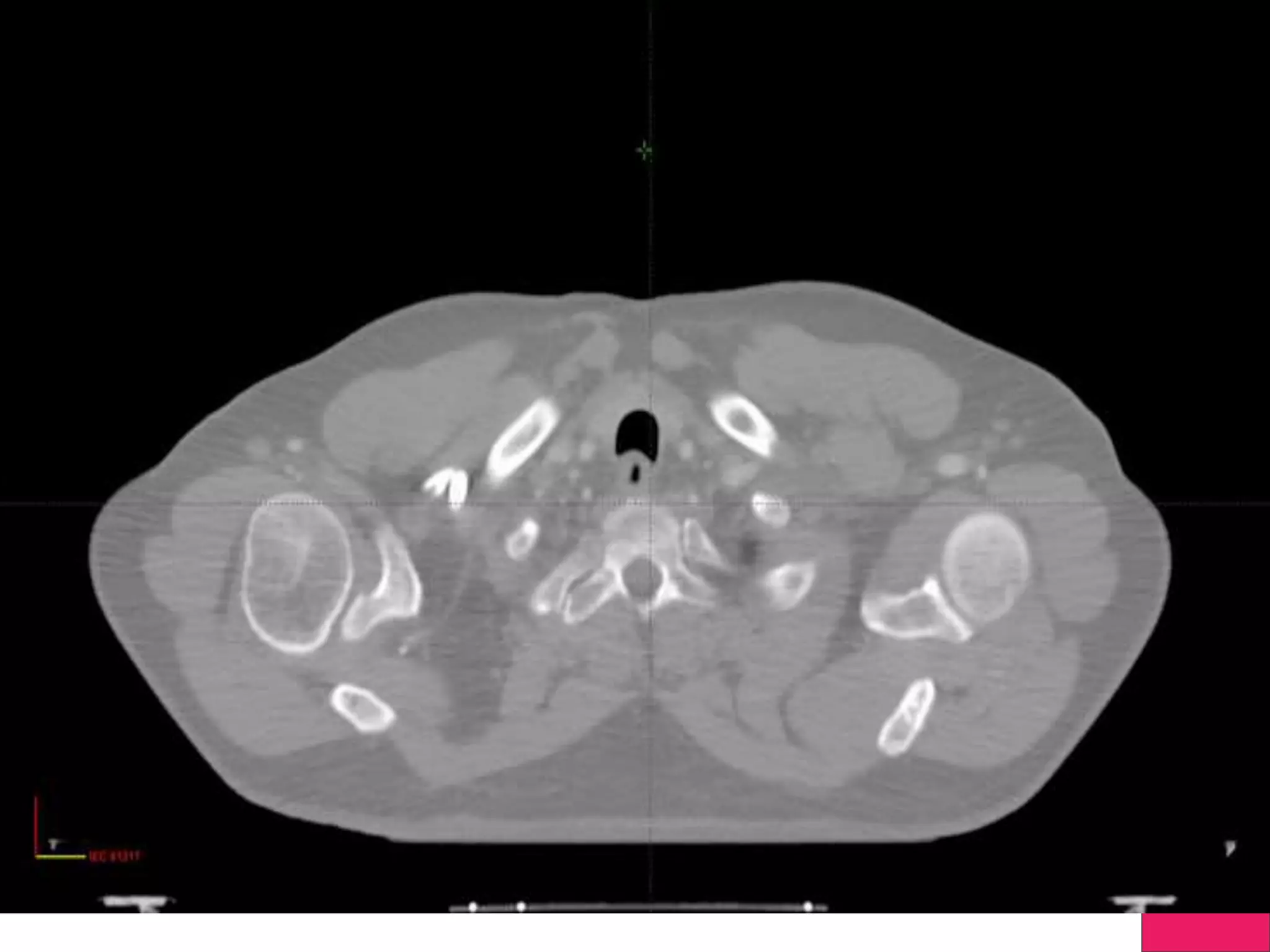
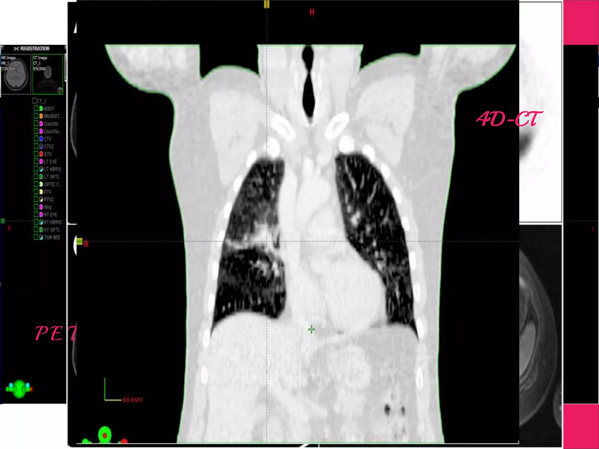
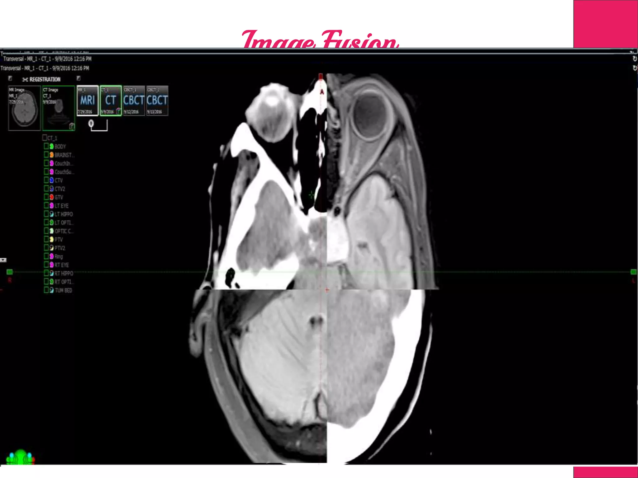
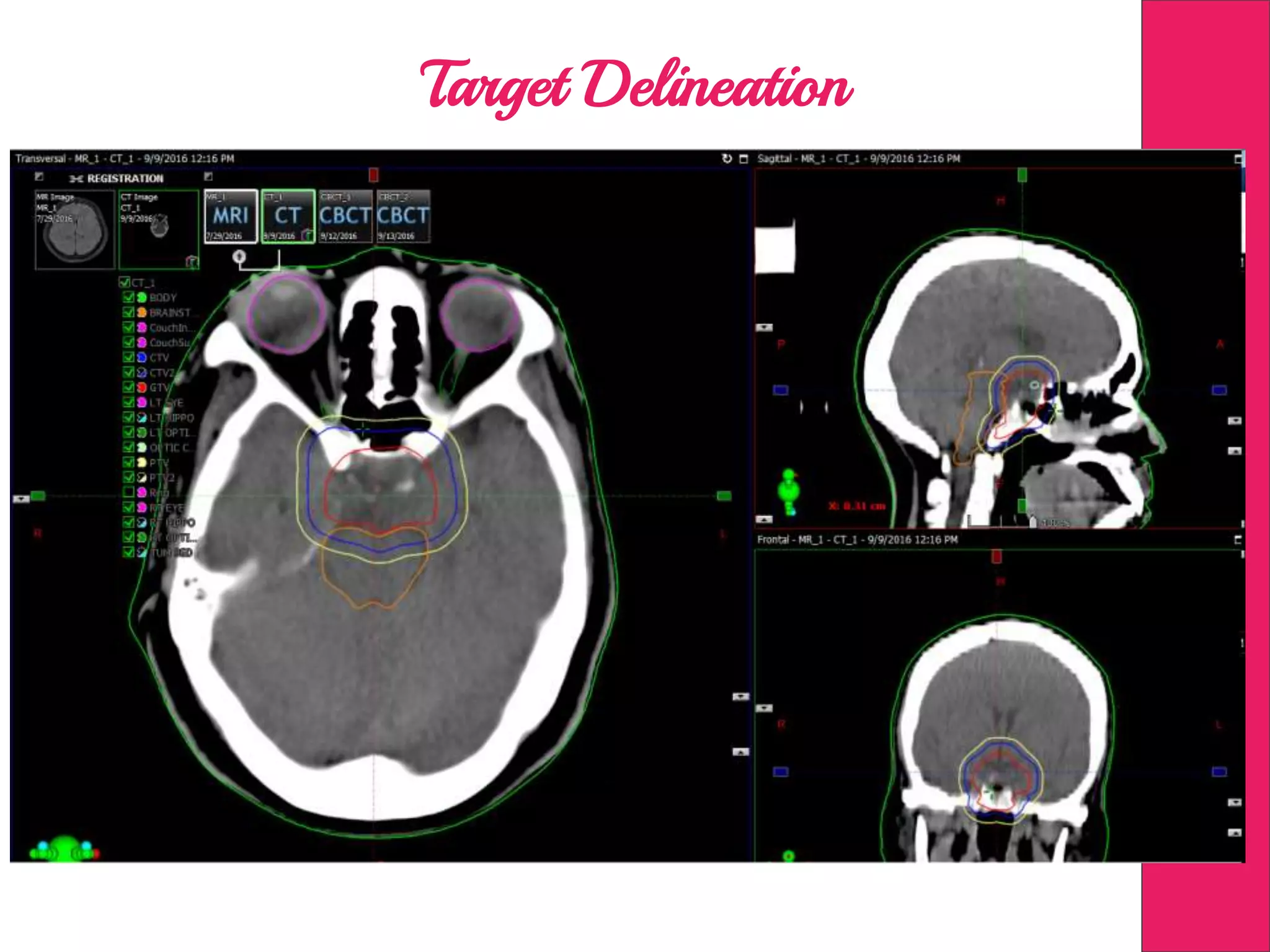
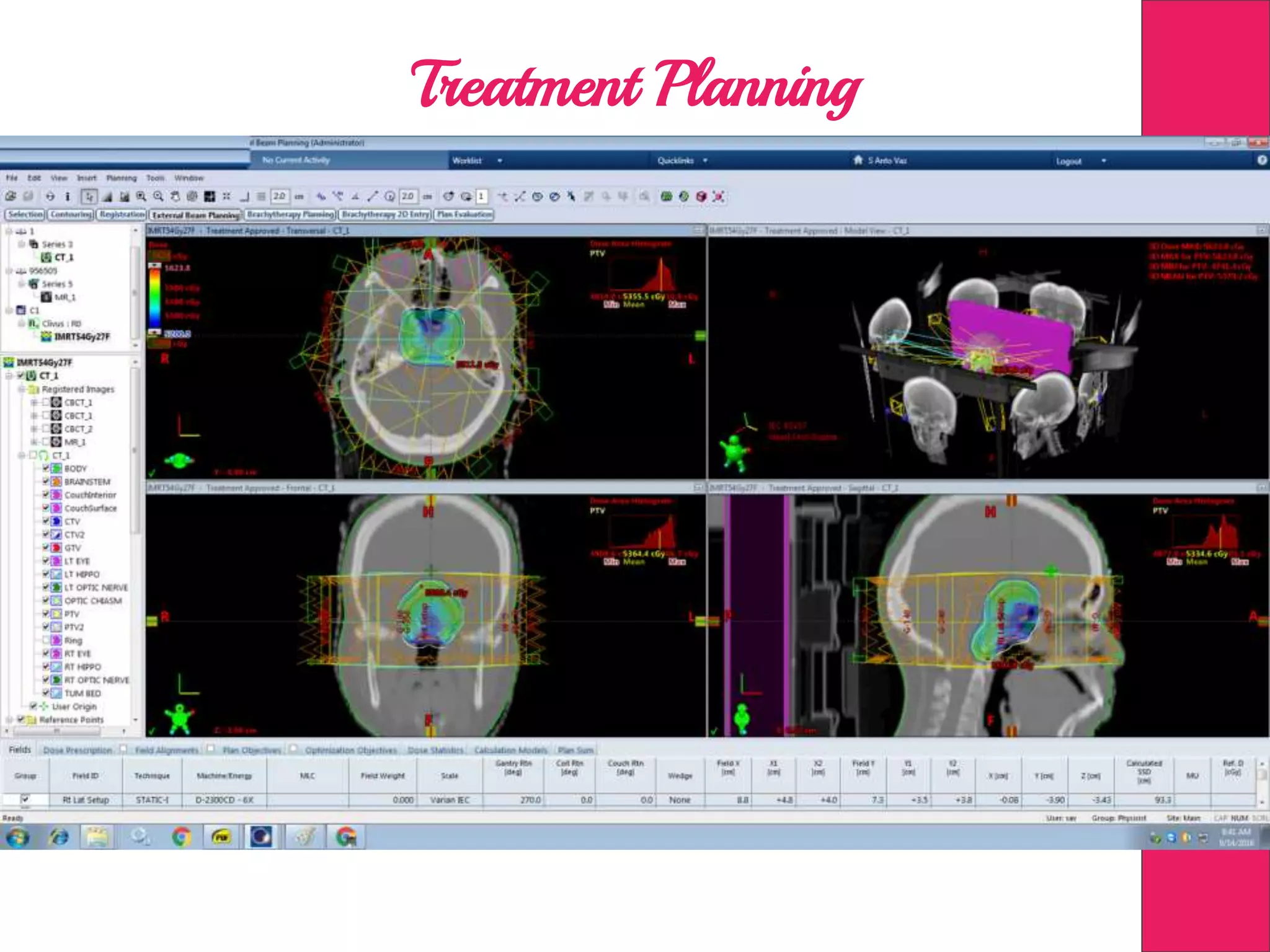
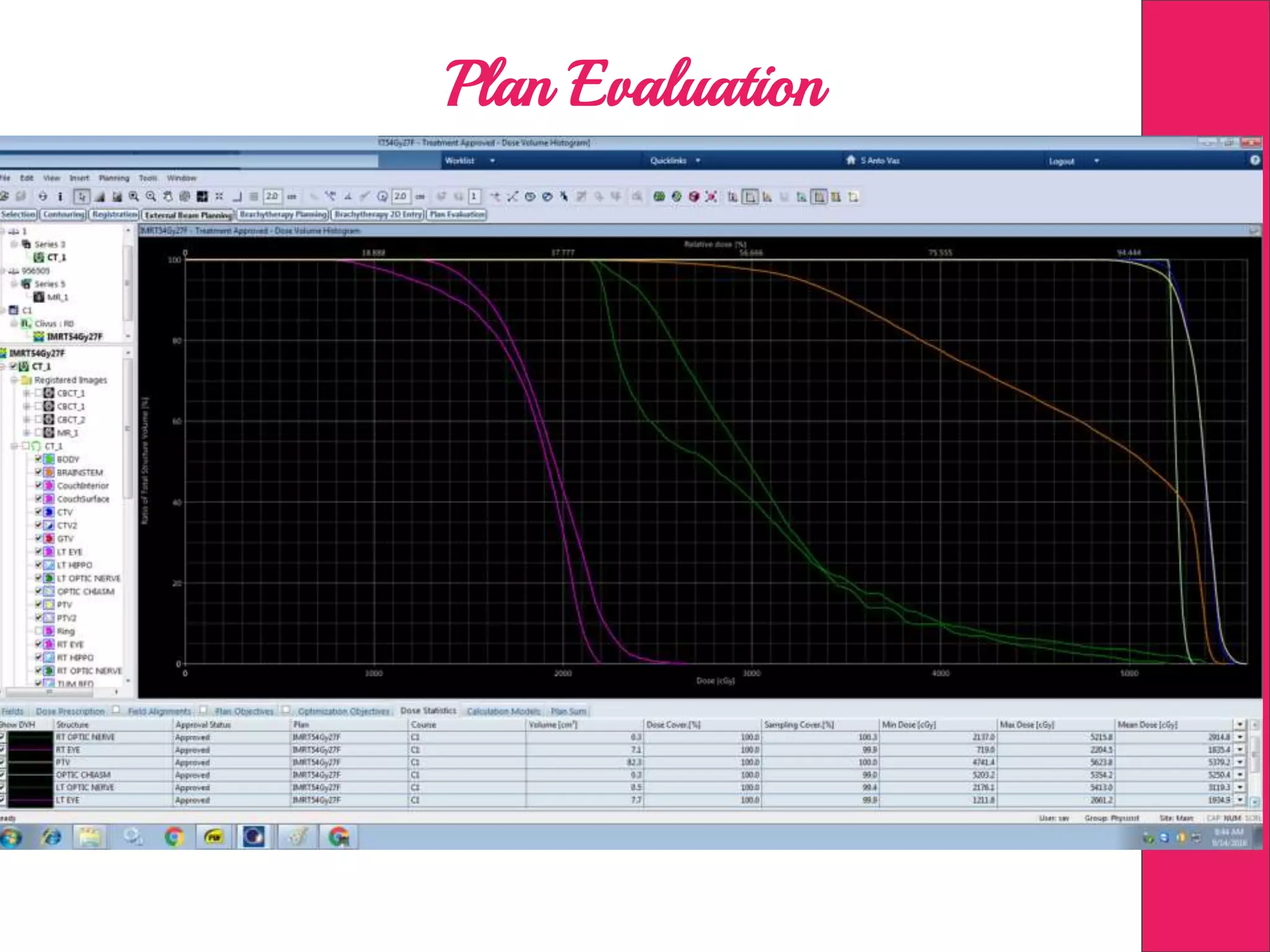
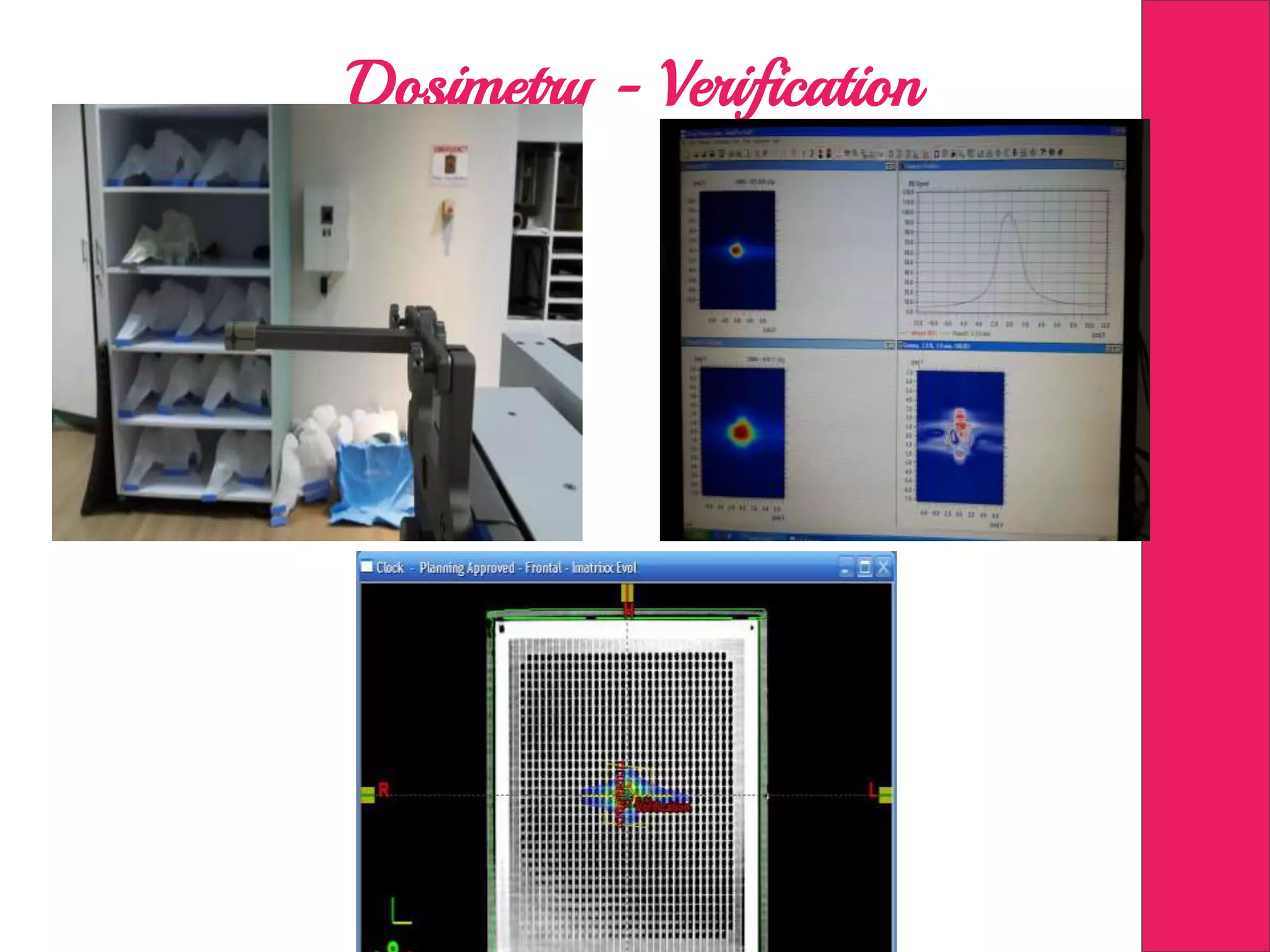
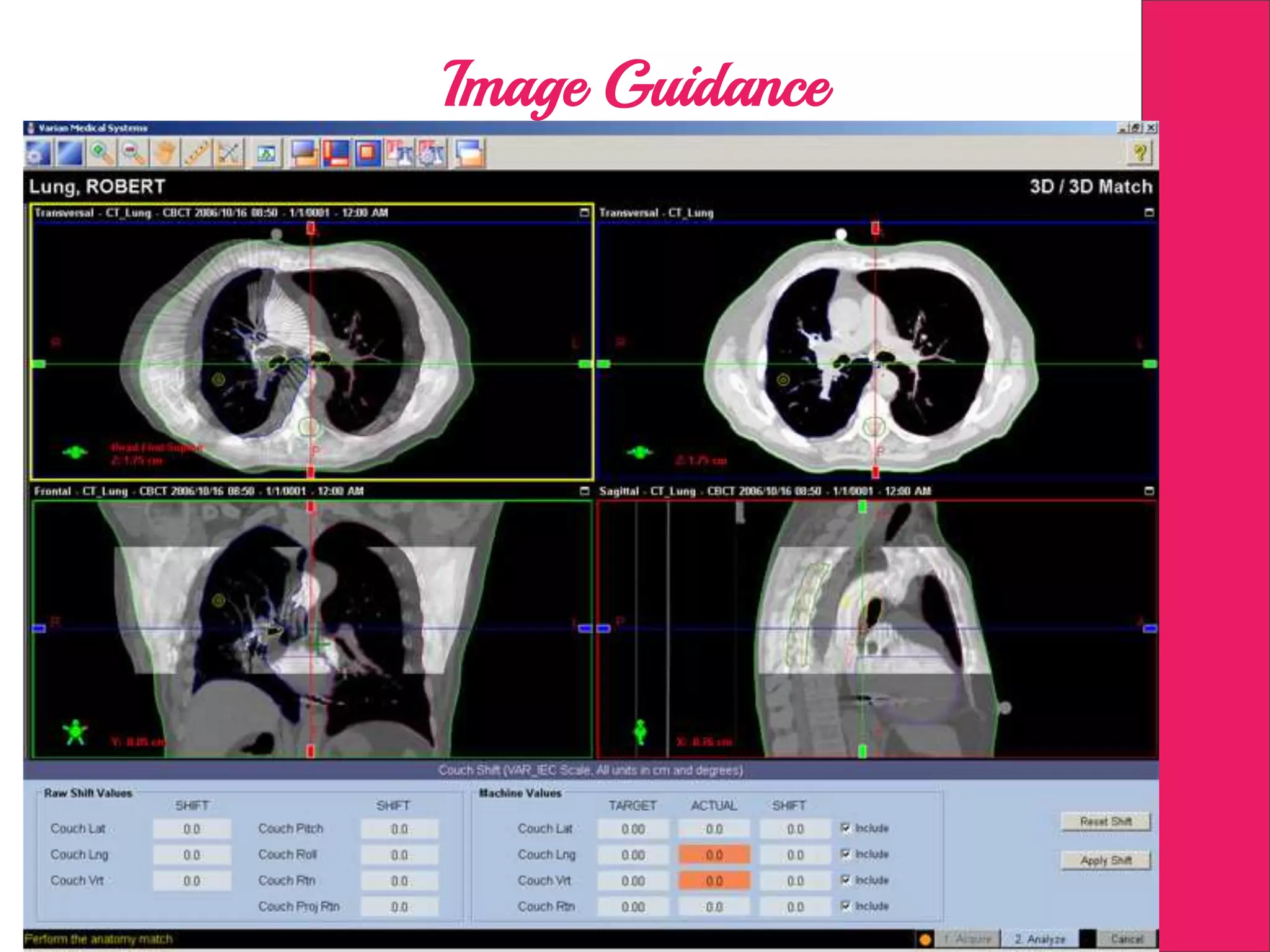
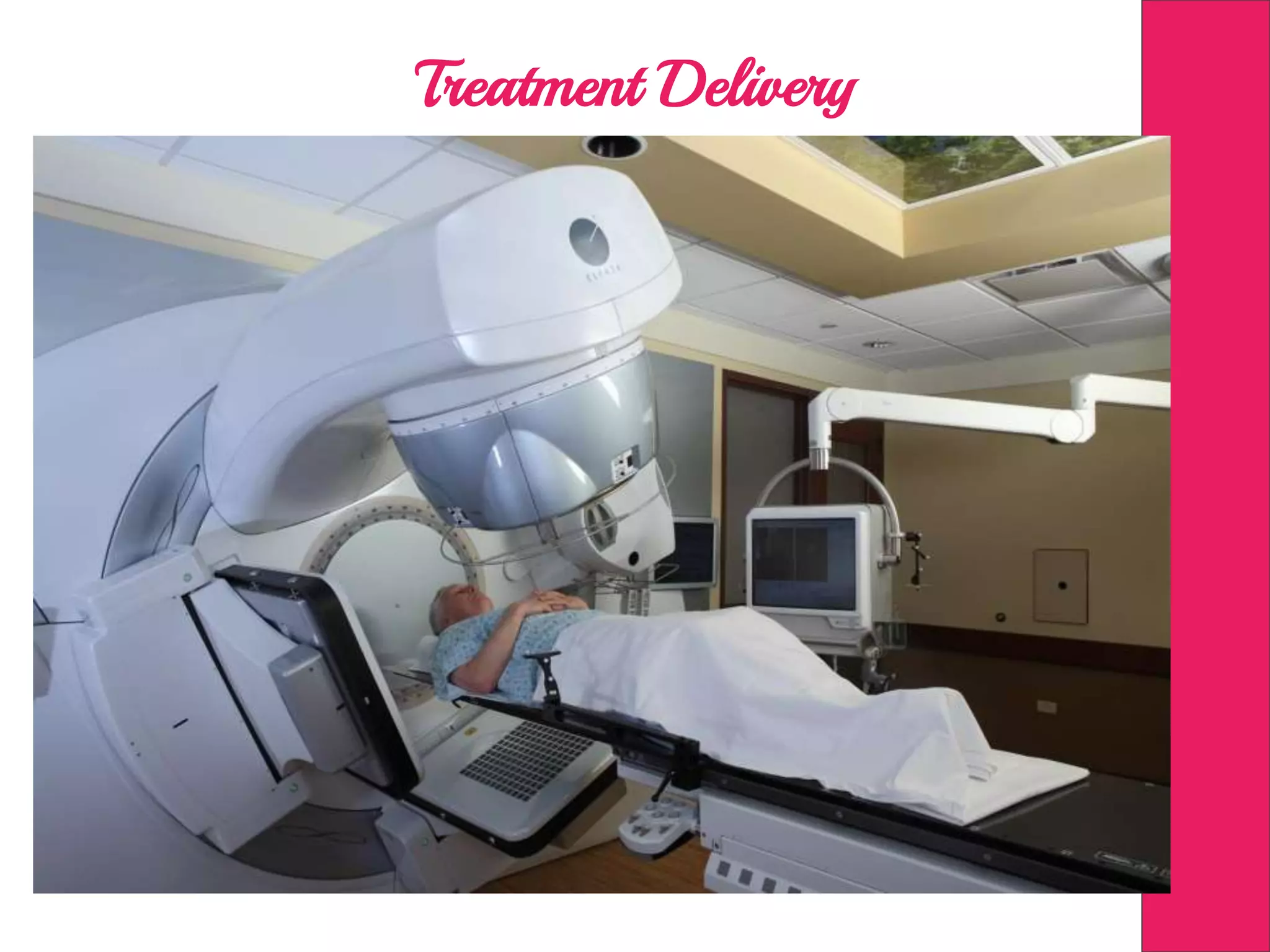
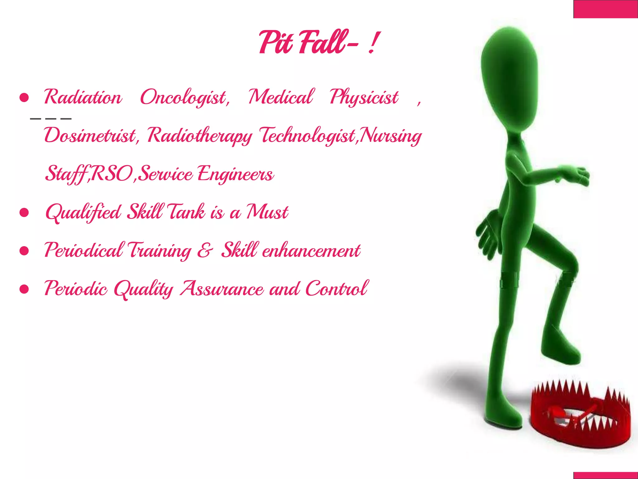
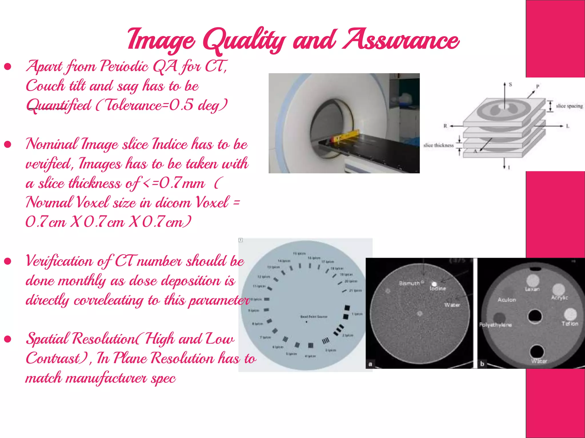
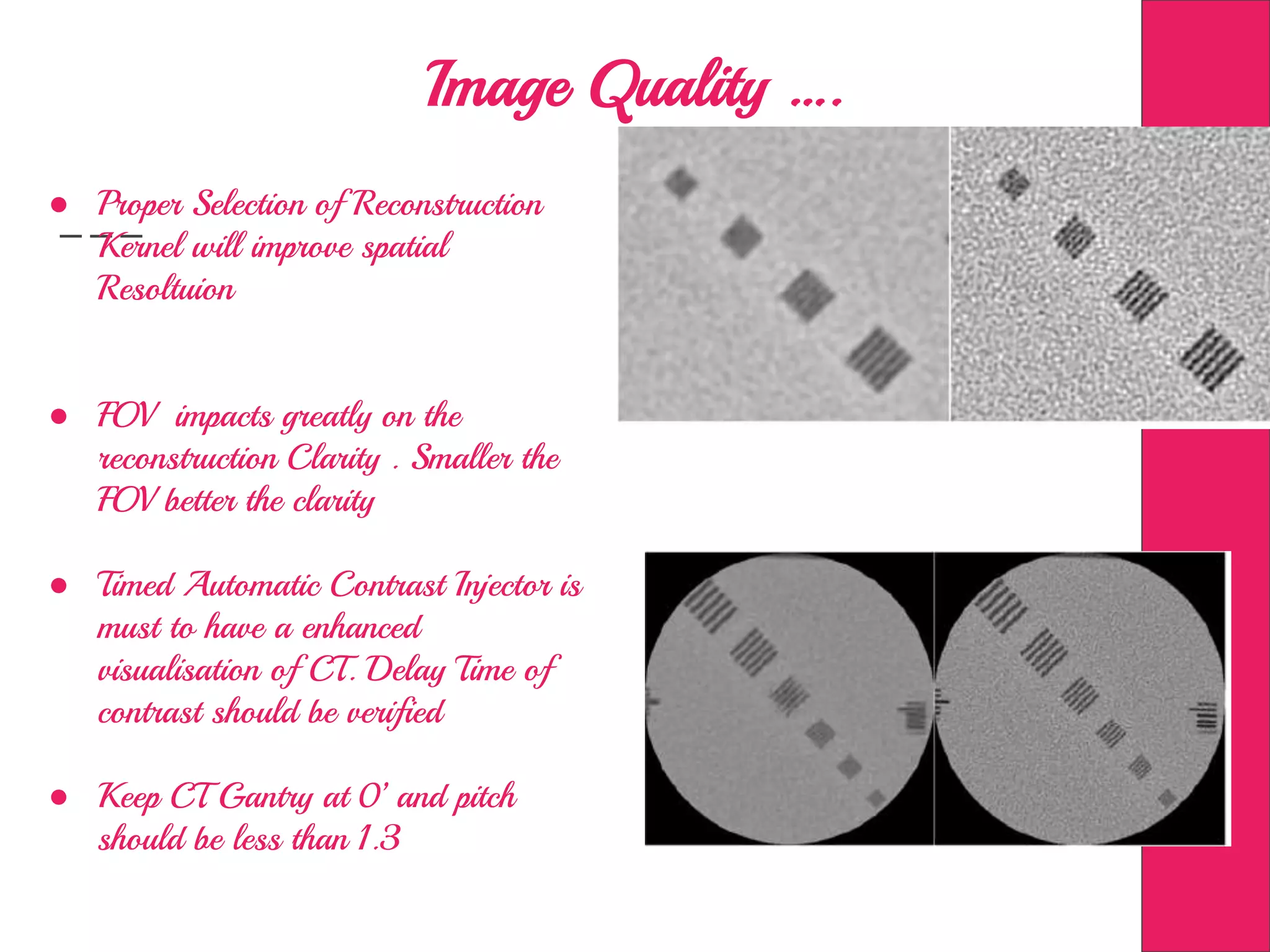
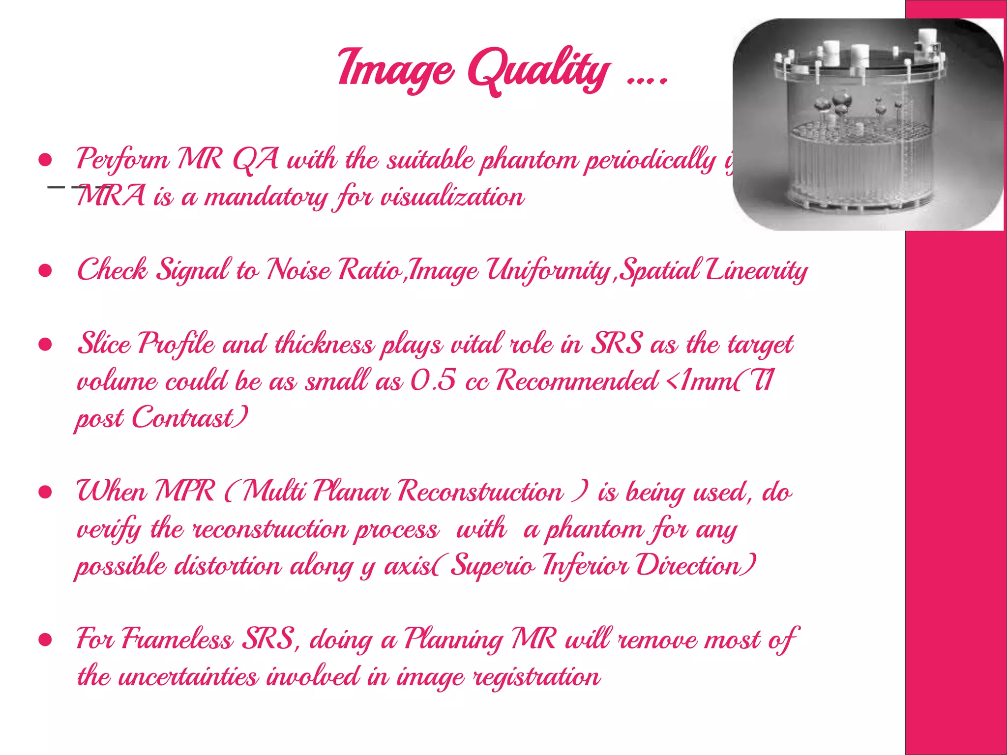
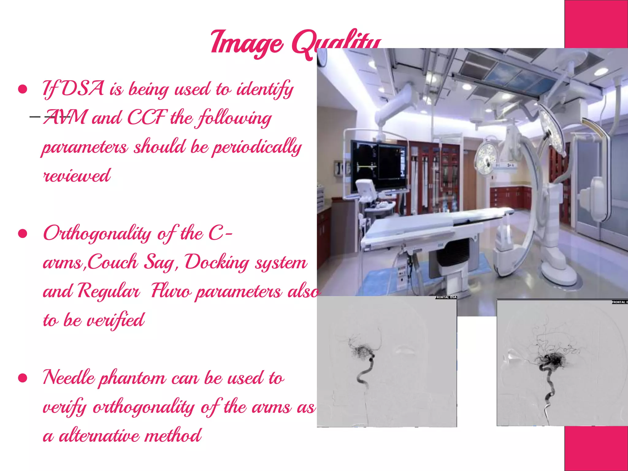
Image Processing in Measurement
guided Radiotherapy and
Geometric accuracy
Anto Vaz S
Kovai Medical Center and Hospitals
Presentation Outline
X-ray a Brief History- (5 slides)
Medical Imaging a Brief History - (11 Slides)
Radiation Oncology Facts and Time stamp- (10 Slides)
2-D, 3-DCRT, IMRT , IGRT ,SRS.. - (12 Slides)
Steps involved Radiotherapy - (12 Slides)
Quality Assurance in Imaging and Radiotherapy - (10
Slides)
Radiotherapy- Time Stamp
1895 - X-ray - Wilhelm Roentgen -
Time Stamp Continued….
1896 - Radioactivity - Henri Bequerrel
Time Stamp Continued ….
1900 - α and β rays - Ernest Rutherford
Time Stamp Continued ….
1900 - Radium and Polonium - Marie Sklodowska Curie
X-rays in Medical Field
Crookes Tube to produce X-ray
John Hall Edward used clinical in Jan 1896
Surgically used in Feb 1896
Marie Curie had her mobile X-ray Setup in world war
Helped Surgeons at the Warfront to quickly assess bones,
joints, internal haemorrages
Medical Imaging
X-ray Machine - 2 D Image
Computed Tomography - 3 D Image
Fluroscopy - 2 D Image mutiple frames / sec
2D Radiograph with X-rays
Why ?
Y- Axis
X- Axis
2D Radiograph with X-rays
Why ?
Y- Axis
Z- Axis
3 D Tomograph with X-rays = C.T.
Y- Axis X- Axis
Digital Medical Imaging - Fact Time
● Dicom- Digital Imaging and Communications in Medicine
● Standardised and Formulised in 1980 by NEMA &
ACR
● Common Language to be spoken about Medical Imaging
throughout the World
● First version in 1993 and the latest version in 2011 and
yet to continue
● What is it needed to be common about imaging ?
Digital Medical Imaging - contd...
1-bit 2-bit 4-bit
8-bit 24-bit 12-bit
So What ?
● Human Eye is Capable of differentiating 32 Shades of
Gray(25)
● Normal DisplayMonitor used in CT can distinguish 256
shades of Gray (28)
● Dicom Images contains information about 4096 shades
of Gray (212)
● This value (4096 shades) is beyond Human Eye’s
Perception
● Window Level narrows the range of shade to be viewed
at one time ?
Digital Medical Imaging - Contd...
He is the Reason - !
● Sir Godfrey Hounsfield - Father of Computed
Tomography
● Deviced a setup which will take standard X-ray all
around a patient (1971)
● Combine them to form a 3 D information inside the
patient
● Used a Roating X-ray Tube and a fast computer to
process the Image
● Given different shades based on Density of tissue (-
1000 to 0 to 1000 HU)
Graphically it means
-500 to 200
-200 to 100
25 to 40
25
HU value equates the Electron Density of the Tissue
When are we going - !
Radiotherapy
Started in 1896, Dr Emil Grubbe used X-ray to Treat Cancer
Early 1920s Radioactive elements radium and polonium were
used to produce cutaneous Burns
Low voltage X-rays were used to treat superficial Tumors
For Deep Seated Tumors X-rays of Million volts are needed
Radioactive isotopes like Co-60 Ir-192 Cs-137 are some of the
widely used sources
Photons, Electrons, Protons, Neutrons and Heavy Ion Particles
Machines in Radiotherapy
Radiation Biology
Study of effect of Ionizing Radiation in living organisms
Interaction happen with 10-13 of a second of the Exposure
Free Radicals will be produced in any organic medium
Changes will be produced at the DNA level ex single break,
Double bond break
Normal cells has repairing capacity, cancer cells dont
Effect of Radiation is cummulative
Radiation Physics
Gamma and X-ray
They will deposit energy as they
travel through any medium
Level of deposition of energy
depends type of particle,
Electron Density of the
Medium
Linear Accelerator based Radiotherapy
Video
2-D Radiotherapy
Conformal Radiotherapy
3DCRT
IMRT
Intensity Modulated Radiotherapy Where we modulate the
intensity of radiation using Multi Leaf Collimator
Multiple Beam (7-9 Beams)
Reduce the Radiation going to the Organ at Risk
(Spine,Brainstem,Parotid,Lung,Heart,Kidney,Rectum &
Bladder)
Contd….
IGRT
Image Guided Radiotherapy, will use either 2D(Xray) or 3D
imaging (Cone Beam CT)
Linear Accelerators will have capability of doing a Xray and CT
Recent Development is Linac with MRI- !
Ensure the Efficiency of Treatment with the help of Imaging
Change in Anatomy can be found during treatment and corrected
IGRT
Stereotactic Radio Surgery (SRS)
ste·reo·tac·tic - A technique in which
one can reach a point inside a
frame using rigid Coordinate
System (Cartesian or Polar),
Usually the frame will be attached
to Patient Head
Word coined in late 1940’s
SRS
Stereotactic Brain
Surgery
Stereotactic Radio Surgery Stereotactic Breast Biopsy
SRS
Originally designed with an intention to be used as surgical tool by Leksell
Later on used extensively for Neuro Oncology
It is based on Polar Coordinates (Angle,Depth Anterio Posterior Position)
Proton was the first choice by Physicist Kurt Liden and Radiobiologist Borje
Larsson
Due to complication in Sychrocyclotron, Leksell made simple and practically
effective Gamma- Knife with the same Centre of Arc Principle (Early
1950’s)
In 1953 Linear Particle accelerator developed parallelly at London with similar
approach(4 MeV Electrons)
Late 1980’s Linear Accelerator based SRS started to take main stage
Gamma Knife
First Generation ‘B’ Helmet needs Manual
Positioning of Patient - Prone to Human
Error
‘B’ Helmet fitted with APS Robotic system to
position the Patient
Linac based SRS ( X knife)
Cone, Frameless SRSMicro MLC ,Frame Based SRS Cone,Frame Based SRS
What Now- ?
Steps Involved in Radiotherapy
Positioning of Patient Imaging in CT
Treatment Planning
Image Fusion
Target Delineation
MR, PET, DSA &
4DCT
Plan EvaluationDosimetry
Verification
Image Guidance
Treatment Delivery
Patient
Patient Positioning
Imaging in CT
Supportive Images
Digitally Subtracted Angiograph
M R I
P E T
4D-CT
Image Fusion
Target Delineation
Treatment Planning
Plan Evaluation
Dosimetry - Verification
Image Guidance
Treatment Delivery
Pit Fall- !
● Radiation Oncologist, Medical Physicist ,
Dosimetrist, Radiotherapy Technologist,Nursing
Staff,RSO,Service Engineers
● Qualified Skill Tank is a Must
● Periodical Training & Skill enhancement
● Periodic Quality Assurance and Control
Image Quality and Assurance
● Apart from Periodic QA for CT,
Couch tilt and sag has to be
Quantified (Tolerance=0.5 deg)
● Nominal Image slice Indice has to be
verified, Images has to be taken with
a slice thickness of <=0.7mm (
Normal Voxel size in dicom Voxel =
0.7cm X 0.7cm X 0.7cm)
● Verification of CT number should be
done monthly as dose deposition is
directly correleating to this parameter
● Spatial Resolution(High and Low
Contrast), In Plane Resolution has to
match manufacturer spec
Image Quality ….
● Proper Selection of Reconstruction
Kernel will improve spatial
Resoltuion
● FOV impacts greatly on the
reconstruction Clarity . Smaller the
FOV better the clarity
● Timed Automatic Contrast Injector is
must to have a enhanced
visualisation of CT. Delay Time of
contrast should be verified
● Keep CT Gantry at 0’ and pitch
should be less than 1.3
Image Quality ….
● Perform MR QA with the suitable phantom periodically if
MRA is a mandatory for visualization
● Check Signal to Noise Ratio,Image Uniformity,Spatial Linearity
● Slice Profile and thickness plays vital role in SRS as the target
volume could be as small as 0.5 cc Recommended <1mm(T1
post Contrast)
● When MPR (Multi Planar Reconstruction ) is being used, do
verify the reconstruction process with a phantom for any
possible distortion along y axis(Superio Inferior Direction)
● For Frameless SRS, doing a Planning MR will remove most of
the uncertainties involved in image registration
Image Quality ….
● If DSA is being used to identify
AVM and CCF the following
parameters should be periodically
reviewed
● Orthogonality of the C-
arms,Couch Sag, Docking system
and Regular Fluro parameters also
to be verified
● Needle phantom can be used to
verify orthogonality of the arms as
a alternative method
Machines in Radiotherapy

Image Processing in Measurement guided Radiotherapy and Geometric accuracy

  • 1.
    Image Processing inMeasurement guided Radiotherapy and Geometric accuracy Anto Vaz S Kovai Medical Center and Hospitals
  • 2.
    Presentation Outline X-ray aBrief History- (5 slides) Medical Imaging a Brief History - (11 Slides) Radiation Oncology Facts and Time stamp- (10 Slides) 2-D, 3-DCRT, IMRT , IGRT ,SRS.. - (12 Slides) Steps involved Radiotherapy - (12 Slides) Quality Assurance in Imaging and Radiotherapy - (10 Slides)
  • 3.
    Radiotherapy- Time Stamp 1895- X-ray - Wilhelm Roentgen -
  • 4.
    Time Stamp Continued…. 1896- Radioactivity - Henri Bequerrel
  • 5.
    Time Stamp Continued…. 1900 - α and β rays - Ernest Rutherford
  • 6.
    Time Stamp Continued…. 1900 - Radium and Polonium - Marie Sklodowska Curie
  • 7.
    X-rays in MedicalField Crookes Tube to produce X-ray John Hall Edward used clinical in Jan 1896 Surgically used in Feb 1896 Marie Curie had her mobile X-ray Setup in world war Helped Surgeons at the Warfront to quickly assess bones, joints, internal haemorrages
  • 9.
    Medical Imaging X-ray Machine- 2 D Image Computed Tomography - 3 D Image Fluroscopy - 2 D Image mutiple frames / sec
  • 10.
    2D Radiograph withX-rays Why ? Y- Axis X- Axis
  • 11.
    2D Radiograph withX-rays Why ? Y- Axis Z- Axis
  • 12.
    3 D Tomographwith X-rays = C.T. Y- Axis X- Axis
  • 13.
    Digital Medical Imaging- Fact Time ● Dicom- Digital Imaging and Communications in Medicine ● Standardised and Formulised in 1980 by NEMA & ACR ● Common Language to be spoken about Medical Imaging throughout the World ● First version in 1993 and the latest version in 2011 and yet to continue ● What is it needed to be common about imaging ?
  • 14.
    Digital Medical Imaging- contd... 1-bit 2-bit 4-bit 8-bit 24-bit 12-bit
  • 15.
    So What ? ●Human Eye is Capable of differentiating 32 Shades of Gray(25) ● Normal DisplayMonitor used in CT can distinguish 256 shades of Gray (28) ● Dicom Images contains information about 4096 shades of Gray (212) ● This value (4096 shades) is beyond Human Eye’s Perception ● Window Level narrows the range of shade to be viewed at one time ?
  • 16.
  • 17.
    He is theReason - ! ● Sir Godfrey Hounsfield - Father of Computed Tomography ● Deviced a setup which will take standard X-ray all around a patient (1971) ● Combine them to form a 3 D information inside the patient ● Used a Roating X-ray Tube and a fast computer to process the Image ● Given different shades based on Density of tissue (- 1000 to 0 to 1000 HU)
  • 18.
    Graphically it means -500to 200 -200 to 100 25 to 40 25
  • 19.
    HU value equatesthe Electron Density of the Tissue
  • 20.
    When are wegoing - !
  • 21.
    Radiotherapy Started in 1896,Dr Emil Grubbe used X-ray to Treat Cancer Early 1920s Radioactive elements radium and polonium were used to produce cutaneous Burns Low voltage X-rays were used to treat superficial Tumors For Deep Seated Tumors X-rays of Million volts are needed Radioactive isotopes like Co-60 Ir-192 Cs-137 are some of the widely used sources Photons, Electrons, Protons, Neutrons and Heavy Ion Particles
  • 22.
  • 23.
  • 24.
  • 25.
  • 26.
  • 27.
  • 28.
    Radiation Biology Study ofeffect of Ionizing Radiation in living organisms Interaction happen with 10-13 of a second of the Exposure Free Radicals will be produced in any organic medium Changes will be produced at the DNA level ex single break, Double bond break Normal cells has repairing capacity, cancer cells dont Effect of Radiation is cummulative
  • 29.
    Radiation Physics Gamma andX-ray They will deposit energy as they travel through any medium Level of deposition of energy depends type of particle, Electron Density of the Medium
  • 30.
  • 31.
  • 32.
  • 33.
  • 34.
  • 35.
    IMRT Intensity Modulated RadiotherapyWhere we modulate the intensity of radiation using Multi Leaf Collimator Multiple Beam (7-9 Beams) Reduce the Radiation going to the Organ at Risk (Spine,Brainstem,Parotid,Lung,Heart,Kidney,Rectum & Bladder)
  • 36.
  • 37.
    IGRT Image Guided Radiotherapy,will use either 2D(Xray) or 3D imaging (Cone Beam CT) Linear Accelerators will have capability of doing a Xray and CT Recent Development is Linac with MRI- ! Ensure the Efficiency of Treatment with the help of Imaging Change in Anatomy can be found during treatment and corrected
  • 38.
  • 39.
    Stereotactic Radio Surgery(SRS) ste·reo·tac·tic - A technique in which one can reach a point inside a frame using rigid Coordinate System (Cartesian or Polar), Usually the frame will be attached to Patient Head Word coined in late 1940’s
  • 40.
    SRS Stereotactic Brain Surgery Stereotactic RadioSurgery Stereotactic Breast Biopsy
  • 41.
    SRS Originally designed withan intention to be used as surgical tool by Leksell Later on used extensively for Neuro Oncology It is based on Polar Coordinates (Angle,Depth Anterio Posterior Position) Proton was the first choice by Physicist Kurt Liden and Radiobiologist Borje Larsson Due to complication in Sychrocyclotron, Leksell made simple and practically effective Gamma- Knife with the same Centre of Arc Principle (Early 1950’s) In 1953 Linear Particle accelerator developed parallelly at London with similar approach(4 MeV Electrons) Late 1980’s Linear Accelerator based SRS started to take main stage
  • 42.
    Gamma Knife First Generation‘B’ Helmet needs Manual Positioning of Patient - Prone to Human Error ‘B’ Helmet fitted with APS Robotic system to position the Patient
  • 43.
    Linac based SRS( X knife) Cone, Frameless SRSMicro MLC ,Frame Based SRS Cone,Frame Based SRS
  • 44.
  • 45.
    Steps Involved inRadiotherapy Positioning of Patient Imaging in CT Treatment Planning Image Fusion Target Delineation MR, PET, DSA & 4DCT Plan EvaluationDosimetry Verification Image Guidance Treatment Delivery Patient
  • 46.
  • 47.
  • 48.
    Supportive Images Digitally SubtractedAngiograph M R I P E T 4D-CT
  • 49.
  • 50.
  • 51.
  • 52.
  • 53.
  • 54.
  • 55.
  • 56.
    Pit Fall- ! ●Radiation Oncologist, Medical Physicist , Dosimetrist, Radiotherapy Technologist,Nursing Staff,RSO,Service Engineers ● Qualified Skill Tank is a Must ● Periodical Training & Skill enhancement ● Periodic Quality Assurance and Control
  • 58.
    Image Quality andAssurance ● Apart from Periodic QA for CT, Couch tilt and sag has to be Quantified (Tolerance=0.5 deg) ● Nominal Image slice Indice has to be verified, Images has to be taken with a slice thickness of <=0.7mm ( Normal Voxel size in dicom Voxel = 0.7cm X 0.7cm X 0.7cm) ● Verification of CT number should be done monthly as dose deposition is directly correleating to this parameter ● Spatial Resolution(High and Low Contrast), In Plane Resolution has to match manufacturer spec
  • 59.
    Image Quality …. ●Proper Selection of Reconstruction Kernel will improve spatial Resoltuion ● FOV impacts greatly on the reconstruction Clarity . Smaller the FOV better the clarity ● Timed Automatic Contrast Injector is must to have a enhanced visualisation of CT. Delay Time of contrast should be verified ● Keep CT Gantry at 0’ and pitch should be less than 1.3
  • 60.
    Image Quality …. ●Perform MR QA with the suitable phantom periodically if MRA is a mandatory for visualization ● Check Signal to Noise Ratio,Image Uniformity,Spatial Linearity ● Slice Profile and thickness plays vital role in SRS as the target volume could be as small as 0.5 cc Recommended <1mm(T1 post Contrast) ● When MPR (Multi Planar Reconstruction ) is being used, do verify the reconstruction process with a phantom for any possible distortion along y axis(Superio Inferior Direction) ● For Frameless SRS, doing a Planning MR will remove most of the uncertainties involved in image registration
  • 61.
    Image Quality …. ●If DSA is being used to identify AVM and CCF the following parameters should be periodically reviewed ● Orthogonality of the C- arms,Couch Sag, Docking system and Regular Fluro parameters also to be verified ● Needle phantom can be used to verify orthogonality of the arms as a alternative method
  • 63.

Editor's Notes

  • #4 German Physicist -Hittroff-Crookes Tube-Barium Platino Cynaide-Accidental Discovery of Ray-Anna Beth - I Saw my Death-1901 first Noble prize in Physics-Father of Radiology- Photography 1826 or 1827
  • #5 French Physicist -Linked Natural Phosphorence occurred on Photographic plates from urantium Salt, Shared Noble Prize with Curie who further researched on radioactivity-1903
  • #6 New Zealand Physicist -nobel prize in 1903 for discovering alpha and Beta rays- later 1903 Gamma Rays - Gold Foil experiment 1908-1921 postulated ruther ford atom model -
  • #7 Polish Physicist (from France) -first women nobel prize 1903winner 25% of the prize - coined word radioactivity-second nobel prize for chemistry Radium and polonium isoloation-died of anaplastic anaemia-kept radium test tubes in her pocket-notes from lab itself high contaminated-one must wear protective clothes to view the notes which were kept in lead containers-
  • #8 Initially surgeons used in warfront only during surgeries-20 xray had been setup by curie in world war 1- first one to train female aides in radiography 1914
  • #18 Idea came up when he was on a vacation-But cormack also theoretically formulated mathematical equation for the same-knighthood given in 1981- started with only brain scan in 1971 -1975 whole body scanner available-died in 2004
  • #29 H20 will form H+ and OH- these free radicals will recombine to form molecules like hydrogen peroxide,
  • #30 Talk of about Gamma and Xray Production Nucleus and Orbital Level
  • #31 H20 will form H+ and OH- these free radicals will recombine to form molecules like hydrogen peroxide,
  • #32 How Linear Accelerator Works, ?
  • #35 H20 will form H+ and OH- these free radicals will recombine to form molecules like hydrogen peroxide,
  • #36 H20 will form H+ and OH- these free radicals will recombine to form molecules like hydrogen peroxide,
  • #38 H20 will form H+ and OH- these free radicals will recombine to form molecules like hydrogen peroxide,
  • #39 H20 will form H+ and OH- these free radicals will recombine to form molecules like hydrogen peroxide,
  • #40 H20 will form H+ and OH- these free radicals will recombine to form molecules like hydrogen peroxide,
  • #41 H20 will form H+ and OH- these free radicals will recombine to form molecules like hydrogen peroxide,
  • #42 H20 will form H+ and OH- these free radicals will recombine to form molecules like hydrogen peroxide,
  • #43 H20 will form H+ and OH- these free radicals will recombine to form molecules like hydrogen peroxide,
  • #44 H20 will form H+ and OH- these free radicals will recombine to form molecules like hydrogen peroxide,
  • #45 H20 will form H+ and OH- these free radicals will recombine to form molecules like hydrogen peroxide,
  • #46 H20 will form H+ and OH- these free radicals will recombine to form molecules like hydrogen peroxide,
  • #47 H20 will form H+ and OH- these free radicals will recombine to form molecules like hydrogen peroxide,
  • #48 H20 will form H+ and OH- these free radicals will recombine to form molecules like hydrogen peroxide,
  • #49 H20 will form H+ and OH- these free radicals will recombine to form molecules like hydrogen peroxide,
  • #50 H20 will form H+ and OH- these free radicals will recombine to form molecules like hydrogen peroxide,
  • #51 H20 will form H+ and OH- these free radicals will recombine to form molecules like hydrogen peroxide,
  • #52 H20 will form H+ and OH- these free radicals will recombine to form molecules like hydrogen peroxide,
  • #53 H20 will form H+ and OH- these free radicals will recombine to form molecules like hydrogen peroxide,
  • #54 H20 will form H+ and OH- these free radicals will recombine to form molecules like hydrogen peroxide,
  • #55 H20 will form H+ and OH- these free radicals will recombine to form molecules like hydrogen peroxide,
  • #56 H20 will form H+ and OH- these free radicals will recombine to form molecules like hydrogen peroxide,
  • #57 H20 will form H+ and OH- these free radicals will recombine to form molecules like hydrogen peroxide,
  • #58 H20 will form H+ and OH- these free radicals will recombine to form molecules like hydrogen peroxide,
  • #59 H20 will form H+ and OH- these free radicals will recombine to form molecules like hydrogen peroxide,
  • #60 H20 will form H+ and OH- these free radicals will recombine to form molecules like hydrogen peroxide,
  • #61 H20 will form H+ and OH- these free radicals will recombine to form molecules like hydrogen peroxide,
  • #62 H20 will form H+ and OH- these free radicals will recombine to form molecules like hydrogen peroxide,
  • #63 H20 will form H+ and OH- these free radicals will recombine to form molecules like hydrogen peroxide,