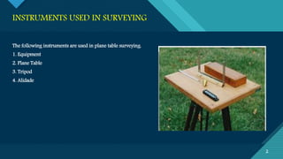
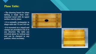
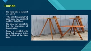
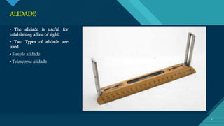
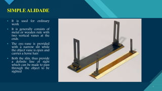
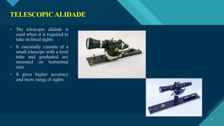
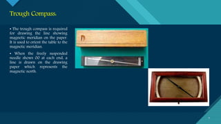
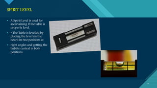
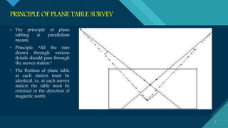
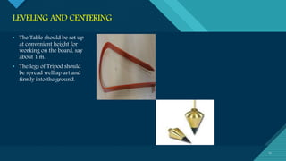
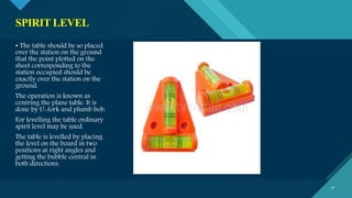
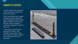
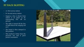
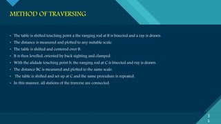
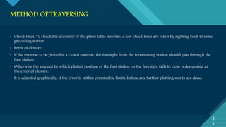
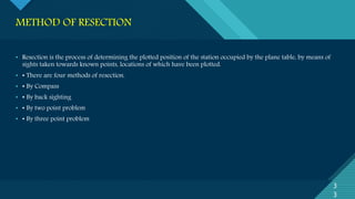
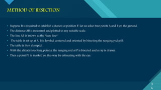
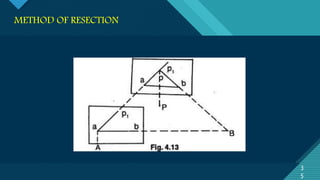
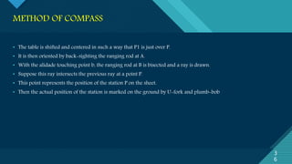
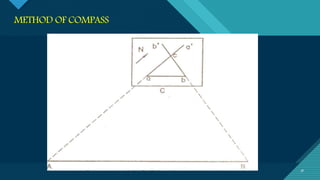
The document describes the instruments and methods used in plane table surveying. It discusses the plane table, alidade, tripod, trough compass, spirit level, and other accessories used. It explains the four main methods of plane table surveying - radiation, intersection, traversing, and resection. It provides details on setting up and orienting the plane table, and outlines the specific steps involved in each surveying method.
INFLUENCE OF NANOSILICA ON THE PROPERTIES OF CONCRETE
Plane table survey
1. Click to edit Master title style
1
PLANE TABLE
SURVEY
S U B : S U RV E Y I N G
B Y: D H A R A D . D AT TA N I
( M . E . T R A N S P O RTAT I O N )
2. Click to edit Master title style
2
INSTRUMENTS USED IN SURVEYING
2
The following instruments are used in plane table surveying.
1. Equipment
2. Plane Table
3. Tripod
4. Alidade
3. Click to edit Master title style
3
EQUIPMENTS AND ACCESSORIES FOR PLANE
TABLING
3
Accessories
• Trough Compass
• Spirit level
• U-Fork with Plumb bob
• Water proof cover
• Drawing paper
• Pins
• Drawing accessories
4. Click to edit Master title style
4
Plane Table:
4
• The drawing board for plane
tabling is made from well-
seasoned wood with its upper
surface exactly plane.
• It is normally rectangular in
shape with size 75 cm x 60 cm
• It is mounted on a tripod and
clamps are provided to fix it in
any direction. The table can
revolved about its vertical axis
and can be clamped in any
position, when necessary.
5. Click to edit Master title style
5 5
• The plane table is mounted
on a tripod
• • The tripod is generally of
open frame type, combined
rigidity with lightness.
• The tripod may be made to
fold for convenience of
transportation.
• Tripod is provided with
three foot screws at its top
for levelling of the plane
table.
TRIPOD:
6. Click to edit Master title style
6
ALIDADE
6
• The alidade is useful for
establishing a line of sight.
• Two Types of alidade are
used.
• Simple alidade
• Telescopic alidade
7. Click to edit Master title style
7
SIMPLEALIDADE
7
• It is used for ordinary
work
• It is generally consists of
metal or wooden rule with
two vertical vanes at the
ends.
• The eye-vane is provided
with a narrow slit while
the object vane is open and
carries a horse hair.
• Both the slits, thus provide
a definite line of sight
which can be made to pass
through the object to be
sighted
8. Click to edit Master title style
8
TELESCOPICALIDADE
8
• The telescopic alidade is
used when it is required to
take inclined sights.
• It essentially consists of a
small telescope with a level
tube and graduated arc
mounted on horizontal
axis.
• It gives higher accuracy
and more range of sights.
9. Click to edit Master title style
9
Trough Compass:
9
• The trough compass is required
for drawing the line showing
magnetic meridian on the paper.
It is used to orient the table to the
magnetic meridian.
• When the freely suspended
needle shows 00 at each end, a
line is drawn on the drawing
paper which represents the
magnetic north.
10. Click to edit Master title style
10
SPIRIT LEVEL
10
• A Spirit Level is used for
ascertaining If the table is
properly level.
• • The Table is levelled by
placing the level on the
board in two positions at
• right angles and getting the
bubble central in both
positions.
11. Click to edit Master title style
11
U-FORK WITH PLUMB BOB
11
• U-fork with plumb bob is used
for centring the table over the
point or station occupied by
the plane table when the
plotted position of that point is
already on the sheet.
• Also, in the beginning of the
work, it is used for
transferring the ground point
on the sheet
12. Click to edit Master title style
12
WATER PROOF COVER & DRAWING PAPER
12
• An umbrella is used to
protect the drawing paper
from rain.
• Drawing paper is used for
plotting the ground details.
13. Click to edit Master title style
13
1
3
• The plan is drawn by the surveyor himself while the area to be surveyed is before his eyes.
• Therefore, there is no possibility of omitting the necessary measurements.
• The surveyor Can compare the plotted work with the actual features of the area.
MAJOR ADVANTAGES OF PLANE TABLE SURVEYING
14. Click to edit Master title style
14
ADVANTAGES & DISADVANTAGES
1
4
ADVANTAGES
• It is simple and cheaper than the theodolite survey.
• It is most suitable for small scale maps.
• No great skill is required to produce a satisfactory map and work may be entrusted to a subordinate.
• It is useful in magnetic areas where compass may not be used.
• The mistakes in writing field books are eliminated.
DISADVANTAGES
• It is not intended for very accurate work.
• It is not suitable in monsoon.
• It is essentially a tropical instrument.
• Due to heaviness, it is inconvenient to transport.
• Since there are so many accessories, there is likelihood of them being lost.
15. Click to edit Master title style
15
PRINCIPLE OF PLANE TABLE SURVEY
15
• The principle of plane
tabling is parallelism
means,
• Principle: “All the rays
drawn through various
details should pass through
the survey station.”
• The Position of plane table
at each station must be
identical, i.e. at each survey
station the table must be
oriented in the direction of
magnetic north.
16. Click to edit Master title style
16
METHOD OF SETTING UP THE PLANE TABLE
1
6
Three processes are involved in setting up the plane table over the station.
• Levelling
• Centring
• Orientation
17. Click to edit Master title style
17
LEVELING AND CENTERING
17
• The Table should be set up
at convenient height for
working on the board, say
about 1 m.
• The legs of Tripod should
be spread well ap art and
firmly into the ground.
18. Click to edit Master title style
18
SPIRIT LEVEL
18
• The table should be so placed
over the station on the ground
that the point plotted on the
sheet corresponding to the
station occupied should be
exactly over the station on the
ground.
The operation is known as
centring the plane table. It is
done by U-fork and plumb bob.
For levelling the table ordinary
spirit level may be used.
The table is levelled by placing
the level on the board in two
positions at right angles and
getting the bubble central in
both directions.
19. Click to edit Master title style
19
ORIENTATION
1
9
• The Process by which the positions occupied by the board at various survey stations are kept parallel is known
as the orientation.
• Thus, when a plane table is properly oriented, the lines on the board are parallel to the lines on ground which
they represent.
• There are two methods of orientation:
• By magnetic needle
• By back sighting
20. Click to edit Master title style
20
ORIENTATION
20
• In this method, the magnetic
north is drawn on paper at a
particular station.
At the next station, the trough
compass is placed along the
line of magnetic north and the
table is turned in such a way
that the ends of magnetic
needle are opposite to zeros of
the scale.
• The board is then fixed in
position by clamps. This
method is inaccurate in the
since that the results are likely
to be affected by the local
attraction.
21. Click to edit Master title style
21
BY BACK SIGHTING
21
• A= First survey station
• B= Second survey station
• Suppose a line is drawn from
station A on paper as ab,
representing line AB on
ground
• The table is turned till the line
of sight bisects the ranging rod
at A.
• The board is then clamped in
this position.
• This method is better than the
previous one and it gives
perfect orientation.
22. Click to edit Master title style
22
METHODS OF PLANE TABLING
2
2
There are four distinct methods of plane tabling:
• Method of Radiation
• Method of Intersection
• Method of Traversing
• Method of Resection
23. Click to edit Master title style
23
2
3
RADIATION METHOD
24. Click to edit Master title style
24
RADIATION METHOD
2
4
• In the radiation method of plane table surveying, the direction of the objects or points to be located are obtained by
drawing radial lines along fiducially edge of alidade after getting the objects or points bisected along the line of
sight of the alidade.
• The horizontal distances are then measured and scaled off on the corresponding radial lines to mark their positions
on the drawing.
25. Click to edit Master title style
25
2
5
• Suppose P is a station on the ground from where the object A, B, C and D are visible.
• The plane table is set up over the station P. A drawing is fixed on the table, which is then leveled and centered A
point p is selected on the sheet to represent the station P.
• The north line is marked on the right-hand top corner of the sheet with trough compass or circular box compass.
• With the alidade touching p, the ranging rod at A,B, C and D are bisected and the rays are drawn.
• The distances PA, PB, PC and PD are measured and plotted to any suitable scale to obtain the points a, b, c and d
representing A,B,C,D on paper.
RADIATION METHOD
26. Click to edit Master title style
26
2
6
METHOD OF INTERSECTION
27. Click to edit Master title style
27
METHOD OF INTERSECTION
2
7
• In intersection method of plane table surveying, the objects or points to be located are obtained at the point of
intersection of radial lines drawn from two different stations.
• In this method, the plotting of plane table stations are to be carried out accurately.
• Checking is important and thus done by taking third sight from another station.
• The intersection method is suitable when distances of objects are large or cannot be measured properly.
• Thus, this method is preferred in small scale survey and for mountainous regions.
• • Suppose A and B are two station and P is the object on the far bank of a river. Now it is required to fix the position
of P on the sheet by the intersection of rays, drawn from A and B.
• The table is set up at A. It is levelled and centred so that a point a on the sheet is just over the station A.
• The north line is marked on the right-hand top corner, the Table is then clamped. With the alidade touching a, the
object P and the ranging rod at B are bisected, and rays are drawn through the fiducial edge on alidade,
28. Click to edit Master title style
28
2
8
• The distance AB is measured and plotted to any suitable scale to obtain point b.
• The table is shifted and centred over B and levelled properly. Now the alidade is placed along the line and
orientation is done by back sighting
• With the alidade touching b, the object P is bisected and a ray is drawn, suppose this ray intersects the previous
rays at point p. the point p is the required plotted position of P
METHOD OF INTERSECTION
29. Click to edit Master title style
29 29
METHOD OF TRAVERSING
30. Click to edit Master title style
30
METHOD OF TRAVERSING
3
0
• This method of plane table surveying is used to plot a traverse in cases stations have not been previously plotted by
some other methods.
• In this method, traverse stations are first selected.
• The stations are plotted by method of radiation by taking back sight on the preceding station and a fore sight to the
following station. Here distances are generally measured by tachometric method and surveying work has to be
performed with great care.
• Suppose A,B,C,D are the traverse stations, The table is set up at the station A, a suitable point a is selected on the
sheet in such a way that the whole area may be plotted in the sheet.
• The table is centered, leveled and clamped.
• The north line is marked on the right-hand top corner of the sheet.
• With the alidade touching point a the ranging rod at B is bisected and a ray is drawn.
• The distance AB is measured and plotted to any suitable scale.
31. Click to edit Master title style
31
3
1
• The table is shifted touching point a the ranging rod at B is bisected and a ray is drawn.
• The distance is measured and plotted to any suitable scale.
• The table is shifted and centered over B.
• It is then levelled, oriented by back sighting and clamped.
• With the alidade touching point b, the ranging rod at C is bisected and ray is drawn.
• The distance BC is measured and plotted to the same scale.
• The table is shifted and set up at C and the same procedure is repeated.
• In this manner, all stations of the traverse are connected.
METHOD OF TRAVERSING
32. Click to edit Master title style
32
3
2
• Check lines. To check the accuracy of the plane table traverse, a few check lines are taken by sighting back to some
preceding station.
• Error of closure .
• If the traverse to be plotted is a closed traverse, the foresight from the terminating station should pass through the
first station.
• Otherwise the amount by which plotted position of the first station on the foresight fails to close is designated as
the error of closure.
• It is adjusted graphically, if the error is within permissible limits, before any further plotting works are done.
METHOD OF TRAVERSING
33. Click to edit Master title style
33
METHOD OF RESECTION
3
3
• Resection is the process of determining the plotted position of the station occupied by the plane table, by means of
sights taken towards known points, locations of which have been plotted.
• • There are four methods of resection.
• • By Compass
• • By back sighting
• • By two point problem
• • By three point problem
34. Click to edit Master title style
34
3
4
• Suppose It is required to establish a station at position P. Let us select two points A and B on the ground.
• The distance AB is measured and plotted to any suitable scale.
• The line AB is known as the “base line”
• The table is set up at A. It is leveled, centered and oriented by bisecting the ranging rod at B.
• The table is then clamped.
• With the alidade touching point a, the ranging rod at P is bisected and a ray is drawn.
• Then a point P1 is marked on this way by estimating with the eye.
METHOD OF RESECTION
35. Click to edit Master title style
35
METHOD OF RESECTION
3
5
36. Click to edit Master title style
36
3
6
• The table is shifted and centered in such a way that P1 is just over P.
• It is then oriented by back-sighting the ranging rod at A.
• With the alidade touching point b, the ranging rod at B is bisected and a ray is drawn.
• Suppose this ray intersects the previous ray at a point P.
• This point represents the position of the station P on the sheet.
• Then the actual position of the station is marked on the ground by U-fork and plumb-bob
METHOD OF COMPASS
37. Click to edit Master title style
37
3
7
• This method is used only for small scale or rough mapping.
• Let A and B be two visible stations which have been plotted on the sheet as a and b. Let C be the instrument station
to be located on the plan.
• Set the table at C and orient it with compass. Clamp the table.
• Pivoting the alidade about a, draw a ray towards A, as Similarly, pivoting the alidade about b, draw a ray towards B,
as bb’, The intersection of aa’ and bb’ will give point c on the paper.
METHOD OF COMPASS
38. Click to edit Master title style
38 38
METHOD OF COMPASS
39. Click to edit Master title style
39
POINTS TO BE KEPT IN MIND IN PLANE TABLING
3
9
• The following points should be kept in mind while doing plane table survey.
• Ground points shall be marked as ABC .. etc. and plan points (on paper) shall be marked as abc etc.
• The rays from survey stations to the objects shall be drawn by dashed line
• The alidade should be properly pivoted while sighting the object.
• The first survey station and the scale of the map shall be so chosen that trough compass.1.234the entire area can be
plotted on the paper.
• 5. While establishing magnetic north on the paper using things causing local attraction shall be kept away of the
table.
• The plane table should be clamped after centring and levelling.
• The table should be rotated only at the time of orientation
40. Click to edit Master title style
40
ERROS IN PLANE TABLE SURVEY
4
0
• The various sources of error may be classified as :
• • Instrumental errors
• • Errors in manipulation and sighting
• • Errors in plotting
41. Click to edit Master title style
41
ERROS IN PLANE TABLE SURVEY-
INSTRUMENTAL ERRORS
4
1
• The surface of drawing board is not plane
• The edge of alidade is not straight.
• The object vane and sight vane are not in a straight line.
• The edge of alidade is not parallel to the line of sight.
• The fixing clamp is not proper.
42. Click to edit Master title style
42
ERROS IN PLANE TABLE SURVEY-
ERRORS IN MANIPULATION AND SIGHTING
4
2
• • Defective Leveling
• • Defective Sighting
• • Defective Orientation
• • Defective Centering
• • Movement of Board between sights
43. Click to edit Master title style
43
ERROS IN PLANE TABLE SURVEY-
ERRORS IN PLOTTING
4
3
• • Defective scale of map
• • Wrongly intersecting the rays drawn from two different stations.
44. Click to edit Master title style
44
REFERENCES
4
4
• • Surveying and leveling- S.C.Saxena
• • Surveying and leveling- R.P.Rethaliya
• • Images: Google Search
• TO BE USED FOR EDUCATION/INFORMATION PURPOSE ONLY