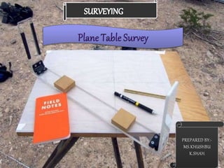
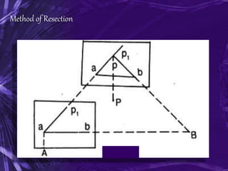
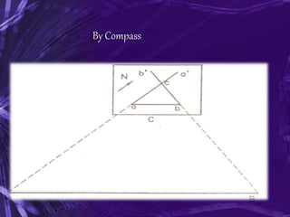
Plane table surveying involves using a plane table, alidade, and other instruments to take field measurements and plot a map. Key principles include maintaining parallelism between lines of sight on the ground and plane table. Common methods are radiation, intersection, traversing, and resection. Sources of error include imperfect instruments, sighting errors, and plotting mistakes. While less accurate than a theodolite, plane table surveying allows mapping in the field with moderate accuracy for small to medium scale maps.
VIP Call Girls Service Kondapur Hyderabad Call +91-8250192130
Introduction to Plane Tabling: A Concise Guide to Plane Table Surveying Methods and Instruments
1.
2. INTRODUCTION TO Plane Tabling
Plane tabling is a graphical method of surveying. In a
plane table surveying plane table is used for taking the
measurements and for plotting the plan in field.
Plane table survey is mainly used for small-scale and
medium scale mapping in open area where great
accuracy is not required. It is also used for plotting the
topographical maps in the field.
3. Principle Of Plane Table Survey
The principle of plane tabling is parallelism means,
Principle: “The rays drawn from ground stations to
objects on drawing sheet are parallel to the lines from
the ground stations to the objects on the ground.
The Position of plane table at each station must be
identical, i.e. at each survey station the table must be
oriented in the direction of magnetic north.
4. INSTRUMENTS USED FOR Plane Tabling
The following instruments are used in plane table surveying.
i. Plane Table
ii. Tripod
iii.Alidade
iv.Trough Compass
v. Spirit level
vi.U-Fork with Plumb bob
5. PLANE TABLE
Plane Table: The drawing board for plane tabling is made from well-
seasoned wood like teak or pine with its upper surface exactly plane.
It is normally rectangular in shape with size 75 cm x 60 cm
It is mounted on a tripod and clamps are provided to fix it in any
direction. The table can revolved about its vertical axis and can be
clamped in any position, when necessary.
7. Tripod
The plane table is mounted on a tripod
The tripod is generally of open frame type, combined rigidity with
lightness. The tripod may be made to fold for convenience of
transportation.
Tripod is provided with three foot screws at its top for leveling of the
plane table.
9. Alidade
The alidade is useful for establishing a line of sight.
Two Types of alidade are used.
I. Simple alidade
II. Telescopic alidade
10. Simple Alidade
It is used for ordinary work.
It is generally made up of metal or wood with two vertical vanes at the
ends.
The eye-vane is provided with a narrow slit while the object vane is
open and carries a horse hair. Both the slits, thus provide a definite
line of sight which can be made to pass through the object to be
sighted
To draw the rays, one of the edge of alidade is beveled and this
perfectly smooth working edge is known as the fiducially edge.
The fiducially edge is graduated to facilitate the plotting of distances
to a scale.
12. Telescopic Alidade
The telescopic alidade is used when it is required to take inclined
sights.
It essentially consists of a small telescope with a level tube and
graduated arc mounted on horizontal axis.
It gives higher accuracy and more range of sights.
14. Trough Compass
The trough compass is required for drawing the line showing magnetic
meridian on the paper. It is used to orient the table to the magnetic
meridian.
When the freely suspended needle shows 00 at each end, a line is
drawn on the drawing paper which represents the magnetic north.
16. Spirit Level
A Spirit Level is used for ascertaining If the table is properly level.
The Table is leveled by placing the level on the board in two positions
at right angles and getting the bubble central in both positions.
18. U-Fork With Plumb bob
U-fork with plumb bob is used for centering the table over the point or
station occupied by the plane table when the plotted position of that point
is already on the sheet.
Also, in the beginning of the work, it is used for transferring the ground
point on the sheet.
20. Method Of Setting Up The Plane Table
Following processes are involved in setting up the plane table over the
station.
I. Fixing the plane table on tripod stand
II. Levelling the table
III.Centering the table
IV.Marking north line
V.Orientation
21. Levelling and Centering
The Table should be set up at convenient height for working on the
board. The legs of Tripod should be spread well apart and firmly into
the ground.
The table should be so placed over the station on the ground that
the point plotted on the sheet corresponding to the station occupied
should be exactly over the station on the ground. The operation is
known as centering the plane table. It is done by U-fork and plumb
bob.
For leveling the table ordinary spirit level may be used. The table is
leveled by placing the level on the board in two positions at right
angles and getting the bubble central in both directions.
24. Orientation
The Process by which the positions occupied by the board at various
survey stations are kept parallel is known as the orientation. Thus, when
a plane table is properly oriented, the lines on the board are parallel to
the lines on ground which they represent.
There are two methods of orientation:
I. By magnetic needle
II. By back sighting
25. By Magnetic Needle
In this method, the magnetic north is drawn on paper at a particular
station. At the next station, the trough compass is placed along the
line of magnetic north and the table is turned in such a way that the
ends of magnetic needle are opposite to zeros of the scale. The
board is then fixed in position by clamps. This method is inaccurate in
the since that the results are likely to be affected by the local
attraction.
26. By Back Sighting
A= First survey station
B= Second survey station
Suppose a line is drawn from station A on paper as
ab, representing line AB on ground
The table is turned till the line of sight bisects the
ranging rod at A. The board is then clamped in this
position.
This method is better than the previous one and it
gives perfect orientation.
28. Methods Of Plane Tabling
There are four distinct methods of plane tabling:
I. Method of Radiation
II. Method of Intersection
III.Method of Traversing
IV.Method of Resection
29. Radiation Method
In this method of plane table surveying, the direction of the objects or
points to be located are obtained by drawing radial lines along fiducially
edge of alidade. Suppose P is a station on the ground from where the
object A, B, C and D are visible.
The plane table is set up over the station P ,which is then leveled and
centered. A point p is selected on the sheet to represent the station P
The north line is marked on the right-hand top corner of the sheet with
trough compass. With the alidade touching p, the ranging rod at A,B, C
and D are bisected and the rays are drawn.
30. Radiation Method
The distances PA, PB, PC and PD are measured and plotted to any
suitable scale to obtain the points a, b, c and d representing A,B,C,D
on paper.
31. Method Of Intersection
In intersection method of plane table surveying, the objects or points to be
located are obtained at the point of intersection of radial lines drawn from
two different stations.
The intersection method is suitable when distances of objects are large or
cannot be measured properly. Thus, this method is preferred in small
scale survey and for mountainous regions.
Suppose A and B are two station and P is the object on the far bank of a
river. Now it is required to fix the position of P on the sheet.
32. Method Of Intersection
The table is set up at A. It is leveled and centered so that a point a on
the sheet is just over the station A. The north line is marked on the
right-hand top corner.
With the alidade touching a, the object P and the ranging rod at B are
bisected, and rays are drawn through the fiducial edge on alidade,
The distance AB is measured and plotted to any suitable scale to
obtain point b.
The table is shifted and centered over B and leveled properly. Now
the alidade is placed along the line ba and orientation is done by back
sighting
33. Method Of Intersection
With the alidade touching b, the object P is bisected and a ray is drawn,
suppose this ray intersects the previous rays at point p. the point p is the
required plotted position of P
34. Method Of Traversing
This method of plane table surveying is used to plot a traverse in
cases stations have not been previously plotted. In this method, the
stations are plotted by method of radiation by taking back sight on the
preceding station and a fore sight to the following station. Here
distances are generally measured by tachometric method and
surveying work has to be performed with great care.
Suppose A,B,C,D are the traverse stations,
The table is set up at the station A, a suitable point a is selected on
the sheet in such a way that the whole area may be plotted in the
sheet. The table is centered, leveled and clamped. The north line is
marked on the right-hand top corner of the sheet.
35. Method Of Traversing
With the alidade touching point a the ranging rod at B is bisected and a
ray is drawn. The distance AB is measured and plotted to any suitable
scale.
36. Method Of Traversing
The table is shifted touching point a the ranging rod at B is bisected
and a ray is drawn. The distance is measured and plotted to any
suitable scale.
The table is shifted and centered over B. It is then leveled, oriented
by back sighting and clamped.
With the alidade touching point b, the ranging rod at C is bisected
and ray is drawn. The distance BC is measured and plotted to the
same scale.
The table is shifted and set up at C and the same procedure is
repeated.
In this manner, all stations of the traverse are connected.
37. Method Of Traversing
Check lines. To check the accuracy of the plane table traverse, a few
check lines are taken by sighting back to some preceding station.
Error of closure . If the traverse to be plotted is a closed traverse, the
foresight from the terminating station should pass through the first
station. Otherwise the amount by which plotted position of the first
station on the foresight fails to close is designated as the error of
closure. It is adjusted graphically, if the error is within permissible
limits, before any further plotting works are done.
38. Method of Resection
Resection is the process of determining the plotted position of the
station occupied by the plane table, by means of sights taken
towards known points, locations of which have been plotted.
There are four methods of resection.
I. By Compass
II. By back sighting
III.By two point problem
IV.By three point problem
39. Method of Resection
Suppose It is required to establish a station at position P. Let us
select two points A and B on the ground. The distance AB is
measured and plotted to any suitable scale. The line AB is known as
the “base line”
The table is set up at A. It is leveled, centered and oriented by
bisecting the ranging rod at B. The table is then clamped.
With the alidade touching point a, the ranging rod at P is bisected and
a ray is drawn. Then a point P1 is marked on this way by estimating
with the eye.
41. Method of Resection
The table is shifted and centered in such a way that P1 is just over P. It
is then oriented by back-sighting the ranging rod at A.
With the alidade touching point b, the ranging rod at B is bisected and a
ray is drawn. Suppose this ray intersects the previous ray at a point P.
This point represents the position of the station P on the sheet. Then
the actual position of the station is marked on the ground by U-fork and
plumb-bob
42. By Compass
This method is used only for small scale or rough mapping.
Let A and B be two visible stations which have been plotted on the
sheet as a and b. Let C be the instrument station to be located on the
plan.
Set the table at C and orient it with compass. Clamp the table.
Pivoting the alidade about a, draw a ray towards A, as Similarly,
pivoting the alidade about b, draw a ray towards B, as bb’, The
intersection of aa’ and bb’ will give point c on the paper.
44. Error In Plane Tabling
The various sources of error may be classified as :
I. Instrumental errors
II. Errors in manipulation and sighting
III.Errors in plotting
45. Instrumental Errors
The surface of drawing board is not plane
The edge of alidade is not straight.
The object vane and sight vane are not
perpendicular to the alidade.
The edge of alidade is not is not parallel to the
line of sight.
The fixing clamp is not proper.
46. Errors In Manipulation And Sighting
Defective Leveling
Defective Sighting
Defective Orientation
Defective Centering
Movement of Board between sights
47. Errors in Plotting
Defective scale of map
Wrongly intersecting the rays drawn from two
different stations.
A good quality of pencil with a very fine pointed end
may not have been used.
Plotting errors may occur due to unnecessary hurry
at the time of plotting and adopting wrong method of
plotting.
48. Advantages of Plane Table Surveying
The plan is drawn by the surveyor himself while the area to be
surveyed is before his eyes. Therefore, there is no possibility of
omitting the necessary measurements.
The surveyor Can compare the plotted work with the actual features
of the area.
It is simple and cheaper than the theodolite survey.
It is most suitable for small scale maps.
No great skill is required to produce a satisfactory map and work
may be entrusted to a subordinate.
It is useful in magnetic areas where compass may not be used.
49. Disadvantages of Plane Table Surveying
It is not intended for very accurate work.
It is not suitable in monsoon.
It is essentially a tropical instrument.
Due to heaviness, it is inconvenient to transport.
Since there are so many accessories, there is
likelihood of them being lost.