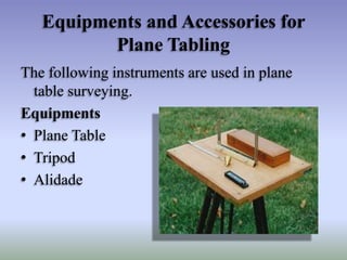
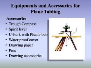
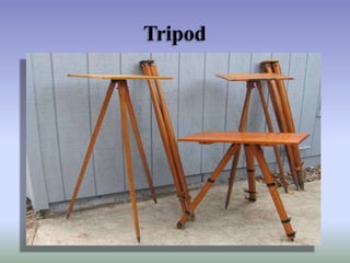
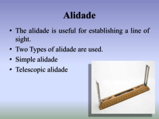
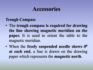
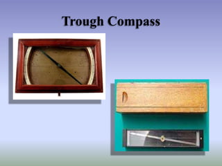
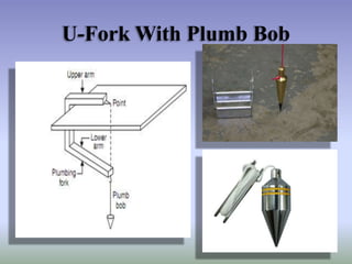
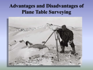
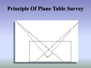
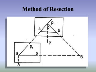
Plane table surveying is a graphical surveying method where field observations and plotting are done simultaneously. The key instruments used are a plane table, alidade, tripod and accessories like trough compass and spirit level. There are different methods used for plane table surveying including radiation, intersection, traversing and resection. The principle of plane table surveying is parallelism, where all rays drawn through survey details should pass through the survey station.


![Module-III SURVEYING-I [BTCVC304]](https://cdn.slidesharecdn.com/ss_thumbnails/module-iii-191020180049-thumbnail.jpg?width=640&height=640&fit=bounds)


