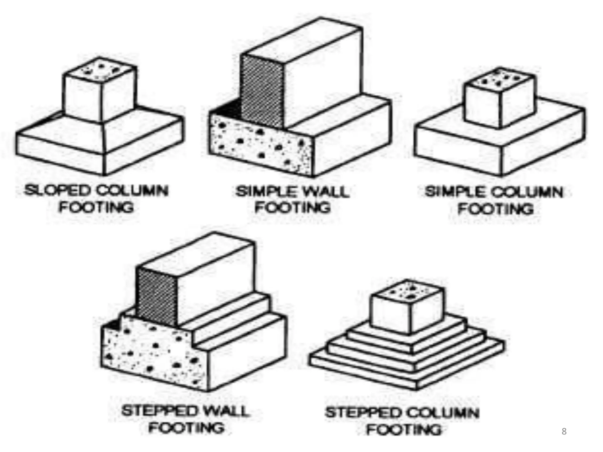
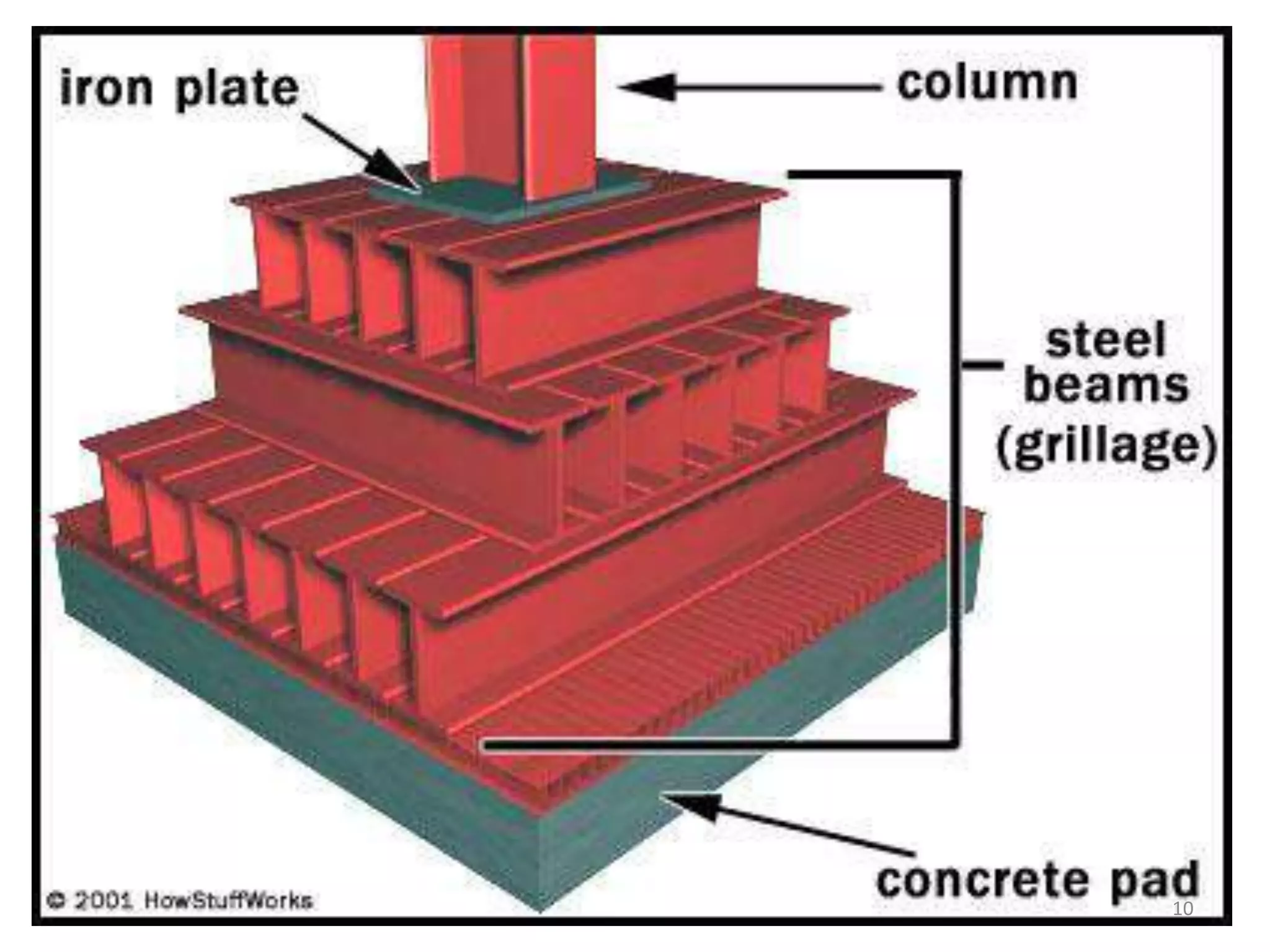
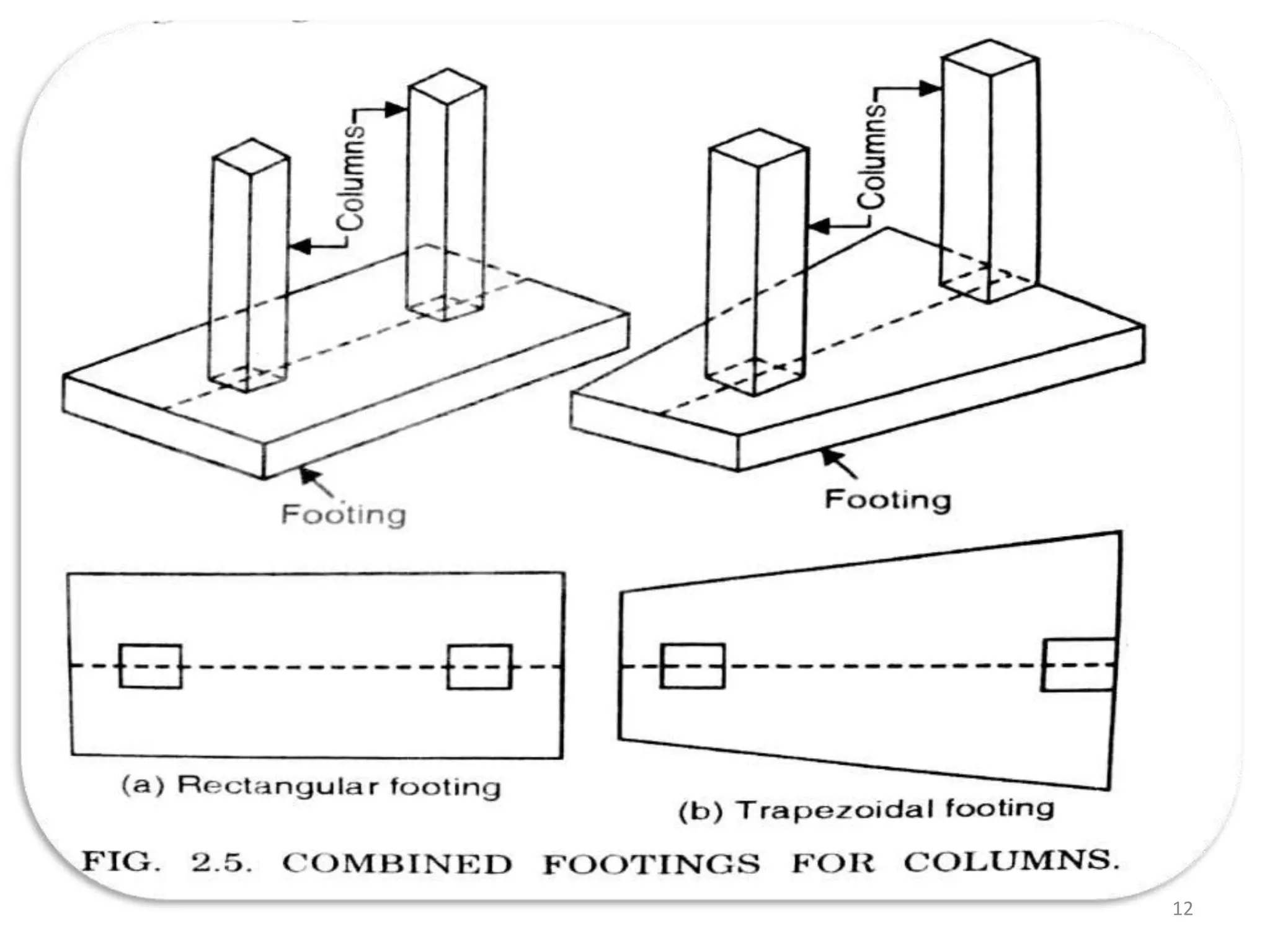
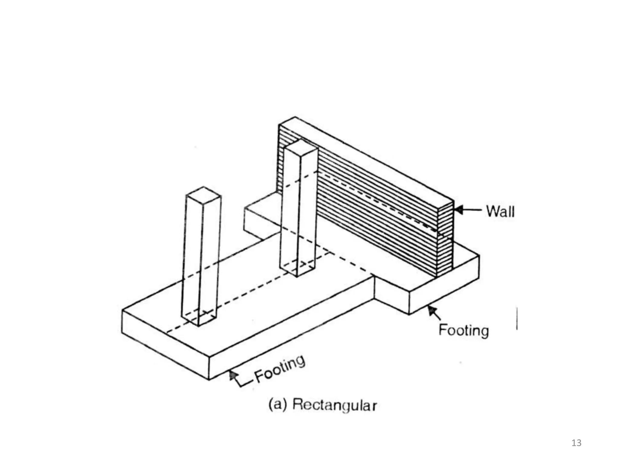
1) The document discusses types of foundations including shallow foundations like spread footings, combined footings, strap footings, mat foundations, and grillage foundations. It also discusses deep foundations like pile foundations, pier foundations, and caisson or well foundations.
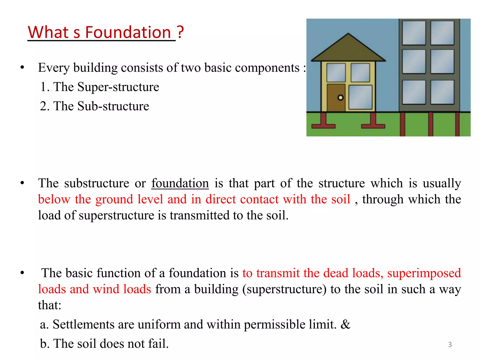
2) Functions of foundations include reducing and distributing load intensity, providing an even and level surface, imparting stability, and protecting against soil movements.
3) Essential requirements for good foundations are withstanding loads without excessive settlement, having sufficient rigidity and depth, and being located to avoid future influences.