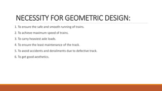
1. Proper geometric design of railway tracks is necessary to ensure safe and smooth running of trains at maximum speeds and loads.
2. Key parameters that determine track geometry include gradients, curve radii, superelevation/cant, and horizontal and vertical curves.
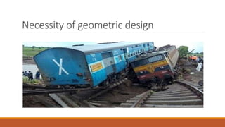
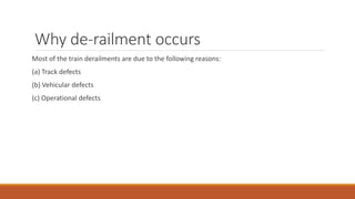
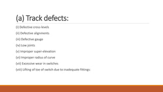
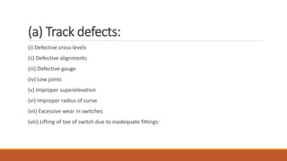
3. Most train derailments are caused by track defects like defective cross-levels, alignments, gauge, joints, superelevation, curve radii, and switch wear.


![11 Geometric Design of Railway Track [Vertical Alignment] (Railway Engineerin...](https://cdn.slidesharecdn.com/ss_thumbnails/geometricdesignofrailwaytrack-ii-200415172410-thumbnail.jpg?width=640&height=640&fit=bounds)


![10 Geometric Design of Railway Track [Horizontal Alignment] (Railway Engineer...](https://cdn.slidesharecdn.com/ss_thumbnails/geometricdesignofrailwaytrack-i-200415171932-thumbnail.jpg?width=640&height=640&fit=bounds)


