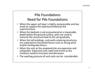
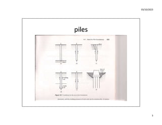
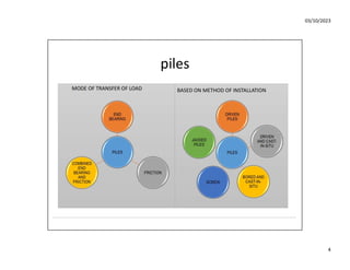
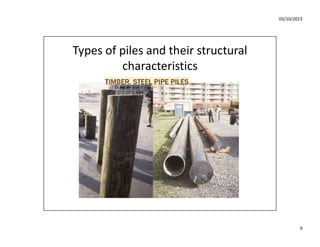
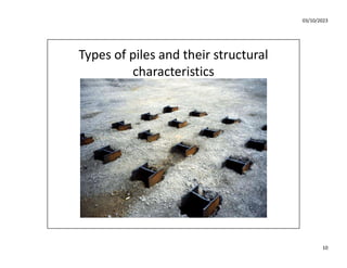
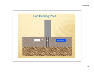
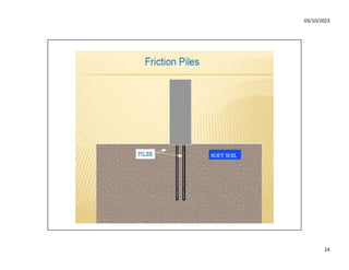
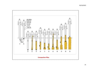
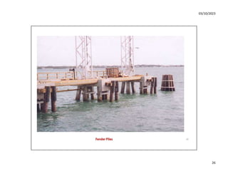
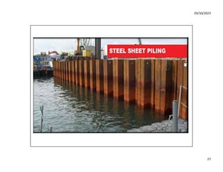
Piles are structural members made of steel, concrete or timber that are used to build deep foundations called pile foundations. Pile foundations are necessary when the soil is too weak, compressible or expansive to support the load of a structure using a shallow foundation. They are also used when lateral forces from wind, earthquakes or soil erosion must be resisted. Piles transmit structural loads deeply into the ground to stronger soil or bedrock layers, ensuring structural safety even in poor soil conditions. Common types of piles include precast concrete, cast-in-place concrete, steel, and timber piles.