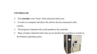
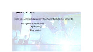
NDUSTRIAL ROBOTICS
The heart of modern manufacturing...
• Paper mill
• Water treatment plant
• HVAC systems
• Special machine based industry
• Power Plants
• Automobile industry
• Product and Process industry & Etc.,
• Automation Solution Provider for Industries like:
We are specialized in Application Development,
Turnkey Projects, Retrofitting, Upgrading of Old Machine
Control Systems, Control Panel Manufacturing.
It is an American subsidiary of the Japanese company Yaskawa Electric Corporation.
The word “MECHATRONICS” derived by Yaskawa Electric Corporation.
It produces robotic automation for industry and robotic applications
Arc welding
Assembly
Clean room
Coating
Dispensing
Material cutting
Materials handling
Materials removal
Spot welding
It is the second largest robotics company in the Americas.
The first successful ultrasonic welding robot
Way of uniqueness
MOTOMAN has done many robotic innovations which are first in the world –
To develop patented design arc welding robot with built in cables on upper arm.
Dual arm 15 axis humanoid robot.
7- Axis type robot
Fastest welding robots.
World’s first 7-axis arc welding and spot welding robot.
Industrial robot is defined by ISO as an automatically
controlled reprogrammable multipurpose manipulator
programmable in three or more axes
INTRODUCTION TO ROBOT
•A robot may not injure a human being or, through inaction, allow a human being to come to harm.
•A robot must obey the orders given to it by human beings, except where such orders would conflict
with the First Law.
•A robot must protect its own existence as long as such protection does not conflict with the First or
Second Law.
Three Laws of Robotics
HISTORY OF INDUSTRIAL ROBOT
INDUSTRIAL ROBOT
SILVER ARM
FAMULUS
UNIMATE
UNIMATE
•Job of transporting die castings
• welding the parts on automobile bodies
FAMULUS
•KUKA’s own industrial robot.
• FAMULUS, this is the first robot to have six electromechanically driven axes.
SILVER ARM
• A robotic arm to do small-parts assembly using feedback from pressure sensors.
• The arm´s fine movements corresponded to those of human fingers.
Robot parameters
Degrees of freedom – This is usually the same as the number of axes.
Working envelope – The region of space a robot can reach.
Kinematics – The actual arrangement of rigid members and joints in the robot,
Payload – How much weight a robot can lift.
Speed – How fast the robot can position the end of its arm.
Acceleration – How quickly an axis can accelerate
Accuracy – How closely a robot can reach a commanded position
Repeatability – How well the robot will return to a programmed position.
Compliance _ Measure of the amount in angle or distance that a robot axis will move
when a force is applied to it.
Maximum payload:
Maximum reach:
Maximum axis:
Maximum mass:
Specification
CONTROLLER
MANIPULATOR
END EFFECTOR
DRIVE
SENSORS
ROBOT ANATOMY
CONTROLLER
The controller is the "brain" of the industrial robotic arm.
It works as a computer and allows the robot to also be connected to other
systems..
The program is inputted with a teach pendant to the controller.
Many of today's industrial robot arms use an interface that resembles or is built on
the Windows operating system.
Limited sequence control
Pick-and-place operations using mechanical stops to set positions
Playback with point-to-point control
Records work cycle as a sequence of points
Then plays back the sequence during program execution
Playback with continuous path control
Greater memory capacity and/or interpolation capability to execute paths
Intelligent control
Exhibits behavior that makes it seem intelligent, e.g., Responds to sensor
OPERATION OF CONTROLLER
MANIPULATORS
Manipulators can vary in size and shape.
The industrial robot arm is the part that positions the end effectors.
Each of these joints gives the robot another degree of freedom.
Many industrial robots in factories today are six axis robots.
.
MANIPULATOR JOINTS
Translational motion
Linear joint (type L)
Orthogonal joint (type O)
Rotary motion
Rotational joint (type R)
Twisting joint (type T)
Revolving joint (type V)
END EFFECTOR
The end effector connects to the robot's arm and functions as a hand.
This part comes in direct contact with the material the robot is manipulating.
Some robots are capable of changing end effectors and can be programmed
for different sets of tasks
DRIVE
 The drive is the engine or motor that moves the links into their designated
positions.
 The links are the sections between the joints.
 Industrial robot arms generally use one of the following types of drives:
hydraulic
electric
pneumatic
ELECTRIC
 Uses electric motors to actuate individual joints
 Preferred drive system in today's robots
HYDRAULIC
 Uses hydraulic pistons and rotary vane actuators
 Noted for their high power and lift capacity
PNEUMATIC
 Typically limited to smaller robots and simple material transfer
applications
SENSORS
 Sensors receive feedback about its environment and also as a sense of
sight and sound.
 The sensor collects information and sends it electronically to the robot
controlled.
 Vision sensors allow a pick and place robot to differentiate between items
to choose and items to ignore.
ROBOT AXIS
Motoman: S (Axis 1)
Motoman: L (Axis 2)
Motoman: U (Axis 3)
Motoman: R (Axis 4)
Motoman: B (Axis 5)
Motoman: T(Axis 6)
TYPES OF INDUSTRIAL ROBOTS:
Articulated
Cartesian
Polar
Cylindrical
SCARA
Delta
ARTICULATED
This robot design features rotary joints.
Can range from simple two joint structures to 10 or more joints.
The arm is connected to the base with a twisting joint.
The links in the arm are connected by rotary joints.
Each joint is called an axis and provides an additional degree of freedom.
ARTICULATED ROBOT
CARTESIAN
These are also called rectilinear or gantry robots.
Cartesian robots have three linear joints that use the Cartesian coordinate system
(X, Y, and Z).
They also may have an attached wrist to allow for rotational movement.
The three prismatic joints deliver a linear motion along the axis.
CARTESIAN ROBOT
CYLINDRICAL
The robot has at least one rotary joint at the base and at least one prismatic joint
to connect the links.
The rotary joint uses a rotational motion along the joint axis, while the
prismatic joint moves in a linear motion.
Cylindrical robots operate within a cylindrical-shaped work envelope.
CYLINDRICAL ROBOT
POLAR
Also called spherical robots, in this configuration the arm is connected to the
base with a twisting joint
A combination of two rotary joints and one linear joint.
The axes form a polar coordinate system and create a spherical-shaped work
envelope.
POLAR ROBOT
SCARA
Commonly used in assembly applications.
this selectively compliant arm for robotic assembly is primarily cylindrical in
design.
It features two parallel joints that provide compliance in one selected plane.
SCARA ROBOT
DELTA
These spider-like robots are built from jointed parallelograms connected to a common
base.
The parallelograms move a single EOAT in a dome-shaped work area.
Heavily used in the food, pharmaceutical, and electronic industries.
This robot configuration is capable of delicate, precise movement.
DELTA ROBOT
Programming Languages For Industrial Robots
Task in plain English
Variable Assembly Language
Epson RC+
ROBOFORTH
Move to P1 (a general safe position)
Move to P2 (an approach to P3)
Move to P3 (a position to pick the object)
Close gripper Move to P4 (an approach to P5)
Move to P5 (a position to place the object)
Open gripper Move to P1 and finish
Task in plain English
1. MOVE P1
2. MOVE P2
3. MOVE P3
4. CLOSEI 0.00
5. MOVE P4
6. MOVE P5
7. OPENI 0.00
8. MOVE P1
.END
Variable Assembly Language
Function Pick Place
Jump P1
Jump P2
Jump P3
On vacuum Wait .1
Jump P4
Jump P5
Off vacuum Wait .1
Jump P1
Fend
Epson RC+
: PICKPLACE
P1
P3 GRIP WITHDRAW
P5 UNGRIP WITHDRAW
P1
;
ROBOFORTH
APPLICATIONS OF INDUSTRIAL ROBOT
Robotic handling operations
Robotic Welding
Robotic Assembly
Robotic Dispensing
Robotic Processing
Other Applications
ROBOTIC HANDLING OPERATIONS
It is the most popular application with 38% of industrial robots worldwide.
This includes
Machine tending
Palatalizing
Various operations for metal machining
Plastic molding
PICKING AND PACKING
• MA1400(MH)
• MH5LS
• SIA30D
• ES200D(MH)
• HP500D
ROBOTIC WELDING
It is the second popular application with 29% of industrial robots worldwide.
This segment mostly includes:
Spot welding
Arc welding
Spot welding
• VS50
• MS120
• MS210
• ES280D(SW)
ARC WELDING
• MA1400(AW)
• VA1400
• MA1440
• MA1800
• MH50-20
ROBOTIC ASSEMBLY
This category of robotic applications seems to have decreased to 10% over the last
few years
Assembly operations include:
Fixing
Press-fitting
Inserting
Disassembling
ASSEMBLY TYPE
• MHJF
• MH3BM
• MH6-10
• SDA10D
• SDA20D
ROBOTIC DISPENSING
Only 4% of the operational robots are doing dispensing.
Here we are talking about
Painting
Gluing
Applying adhesive sealing
Spraying

Robotics

  • 1.
    NDUSTRIAL ROBOTICS The heartof modern manufacturing...
  • 2.
    • Paper mill •Water treatment plant • HVAC systems • Special machine based industry • Power Plants • Automobile industry • Product and Process industry & Etc., • Automation Solution Provider for Industries like: We are specialized in Application Development, Turnkey Projects, Retrofitting, Upgrading of Old Machine Control Systems, Control Panel Manufacturing.
  • 3.
    It is anAmerican subsidiary of the Japanese company Yaskawa Electric Corporation. The word “MECHATRONICS” derived by Yaskawa Electric Corporation. It produces robotic automation for industry and robotic applications Arc welding Assembly Clean room Coating Dispensing Material cutting Materials handling Materials removal Spot welding It is the second largest robotics company in the Americas. The first successful ultrasonic welding robot
  • 4.
    Way of uniqueness MOTOMANhas done many robotic innovations which are first in the world – To develop patented design arc welding robot with built in cables on upper arm. Dual arm 15 axis humanoid robot. 7- Axis type robot Fastest welding robots. World’s first 7-axis arc welding and spot welding robot.
  • 5.
    Industrial robot isdefined by ISO as an automatically controlled reprogrammable multipurpose manipulator programmable in three or more axes INTRODUCTION TO ROBOT
  • 6.
    •A robot maynot injure a human being or, through inaction, allow a human being to come to harm. •A robot must obey the orders given to it by human beings, except where such orders would conflict with the First Law. •A robot must protect its own existence as long as such protection does not conflict with the First or Second Law. Three Laws of Robotics
  • 7.
    HISTORY OF INDUSTRIALROBOT INDUSTRIAL ROBOT SILVER ARM FAMULUS UNIMATE
  • 8.
    UNIMATE •Job of transportingdie castings • welding the parts on automobile bodies
  • 9.
    FAMULUS •KUKA’s own industrialrobot. • FAMULUS, this is the first robot to have six electromechanically driven axes.
  • 10.
    SILVER ARM • Arobotic arm to do small-parts assembly using feedback from pressure sensors. • The arm´s fine movements corresponded to those of human fingers.
  • 11.
    Robot parameters Degrees offreedom – This is usually the same as the number of axes. Working envelope – The region of space a robot can reach. Kinematics – The actual arrangement of rigid members and joints in the robot, Payload – How much weight a robot can lift. Speed – How fast the robot can position the end of its arm. Acceleration – How quickly an axis can accelerate Accuracy – How closely a robot can reach a commanded position Repeatability – How well the robot will return to a programmed position. Compliance _ Measure of the amount in angle or distance that a robot axis will move when a force is applied to it.
  • 12.
    Maximum payload: Maximum reach: Maximumaxis: Maximum mass: Specification
  • 13.
  • 14.
    CONTROLLER The controller isthe "brain" of the industrial robotic arm. It works as a computer and allows the robot to also be connected to other systems.. The program is inputted with a teach pendant to the controller. Many of today's industrial robot arms use an interface that resembles or is built on the Windows operating system.
  • 15.
    Limited sequence control Pick-and-placeoperations using mechanical stops to set positions Playback with point-to-point control Records work cycle as a sequence of points Then plays back the sequence during program execution Playback with continuous path control Greater memory capacity and/or interpolation capability to execute paths Intelligent control Exhibits behavior that makes it seem intelligent, e.g., Responds to sensor OPERATION OF CONTROLLER
  • 16.
    MANIPULATORS Manipulators can varyin size and shape. The industrial robot arm is the part that positions the end effectors. Each of these joints gives the robot another degree of freedom. Many industrial robots in factories today are six axis robots.
  • 17.
    . MANIPULATOR JOINTS Translational motion Linearjoint (type L) Orthogonal joint (type O) Rotary motion Rotational joint (type R) Twisting joint (type T) Revolving joint (type V)
  • 18.
    END EFFECTOR The endeffector connects to the robot's arm and functions as a hand. This part comes in direct contact with the material the robot is manipulating. Some robots are capable of changing end effectors and can be programmed for different sets of tasks
  • 19.
    DRIVE  The driveis the engine or motor that moves the links into their designated positions.  The links are the sections between the joints.  Industrial robot arms generally use one of the following types of drives: hydraulic electric pneumatic
  • 20.
    ELECTRIC  Uses electricmotors to actuate individual joints  Preferred drive system in today's robots HYDRAULIC  Uses hydraulic pistons and rotary vane actuators  Noted for their high power and lift capacity PNEUMATIC  Typically limited to smaller robots and simple material transfer applications
  • 21.
    SENSORS  Sensors receivefeedback about its environment and also as a sense of sight and sound.  The sensor collects information and sends it electronically to the robot controlled.  Vision sensors allow a pick and place robot to differentiate between items to choose and items to ignore.
  • 22.
    ROBOT AXIS Motoman: S(Axis 1) Motoman: L (Axis 2) Motoman: U (Axis 3) Motoman: R (Axis 4) Motoman: B (Axis 5) Motoman: T(Axis 6)
  • 23.
    TYPES OF INDUSTRIALROBOTS: Articulated Cartesian Polar Cylindrical SCARA Delta
  • 24.
    ARTICULATED This robot designfeatures rotary joints. Can range from simple two joint structures to 10 or more joints. The arm is connected to the base with a twisting joint. The links in the arm are connected by rotary joints. Each joint is called an axis and provides an additional degree of freedom.
  • 25.
  • 26.
    CARTESIAN These are alsocalled rectilinear or gantry robots. Cartesian robots have three linear joints that use the Cartesian coordinate system (X, Y, and Z). They also may have an attached wrist to allow for rotational movement. The three prismatic joints deliver a linear motion along the axis.
  • 27.
  • 28.
    CYLINDRICAL The robot hasat least one rotary joint at the base and at least one prismatic joint to connect the links. The rotary joint uses a rotational motion along the joint axis, while the prismatic joint moves in a linear motion. Cylindrical robots operate within a cylindrical-shaped work envelope.
  • 29.
  • 30.
    POLAR Also called sphericalrobots, in this configuration the arm is connected to the base with a twisting joint A combination of two rotary joints and one linear joint. The axes form a polar coordinate system and create a spherical-shaped work envelope.
  • 31.
  • 32.
    SCARA Commonly used inassembly applications. this selectively compliant arm for robotic assembly is primarily cylindrical in design. It features two parallel joints that provide compliance in one selected plane.
  • 33.
  • 34.
    DELTA These spider-like robotsare built from jointed parallelograms connected to a common base. The parallelograms move a single EOAT in a dome-shaped work area. Heavily used in the food, pharmaceutical, and electronic industries. This robot configuration is capable of delicate, precise movement.
  • 35.
  • 36.
    Programming Languages ForIndustrial Robots Task in plain English Variable Assembly Language Epson RC+ ROBOFORTH
  • 37.
    Move to P1(a general safe position) Move to P2 (an approach to P3) Move to P3 (a position to pick the object) Close gripper Move to P4 (an approach to P5) Move to P5 (a position to place the object) Open gripper Move to P1 and finish Task in plain English
  • 38.
    1. MOVE P1 2.MOVE P2 3. MOVE P3 4. CLOSEI 0.00 5. MOVE P4 6. MOVE P5 7. OPENI 0.00 8. MOVE P1 .END Variable Assembly Language
  • 39.
    Function Pick Place JumpP1 Jump P2 Jump P3 On vacuum Wait .1 Jump P4 Jump P5 Off vacuum Wait .1 Jump P1 Fend Epson RC+
  • 40.
    : PICKPLACE P1 P3 GRIPWITHDRAW P5 UNGRIP WITHDRAW P1 ; ROBOFORTH
  • 41.
    APPLICATIONS OF INDUSTRIALROBOT Robotic handling operations Robotic Welding Robotic Assembly Robotic Dispensing Robotic Processing Other Applications
  • 42.
    ROBOTIC HANDLING OPERATIONS Itis the most popular application with 38% of industrial robots worldwide. This includes Machine tending Palatalizing Various operations for metal machining Plastic molding
  • 43.
    PICKING AND PACKING •MA1400(MH) • MH5LS • SIA30D • ES200D(MH) • HP500D
  • 44.
    ROBOTIC WELDING It isthe second popular application with 29% of industrial robots worldwide. This segment mostly includes: Spot welding Arc welding
  • 45.
    Spot welding • VS50 •MS120 • MS210 • ES280D(SW)
  • 46.
    ARC WELDING • MA1400(AW) •VA1400 • MA1440 • MA1800 • MH50-20
  • 47.
    ROBOTIC ASSEMBLY This categoryof robotic applications seems to have decreased to 10% over the last few years Assembly operations include: Fixing Press-fitting Inserting Disassembling
  • 48.
    ASSEMBLY TYPE • MHJF •MH3BM • MH6-10 • SDA10D • SDA20D
  • 49.
    ROBOTIC DISPENSING Only 4%of the operational robots are doing dispensing. Here we are talking about Painting Gluing Applying adhesive sealing Spraying