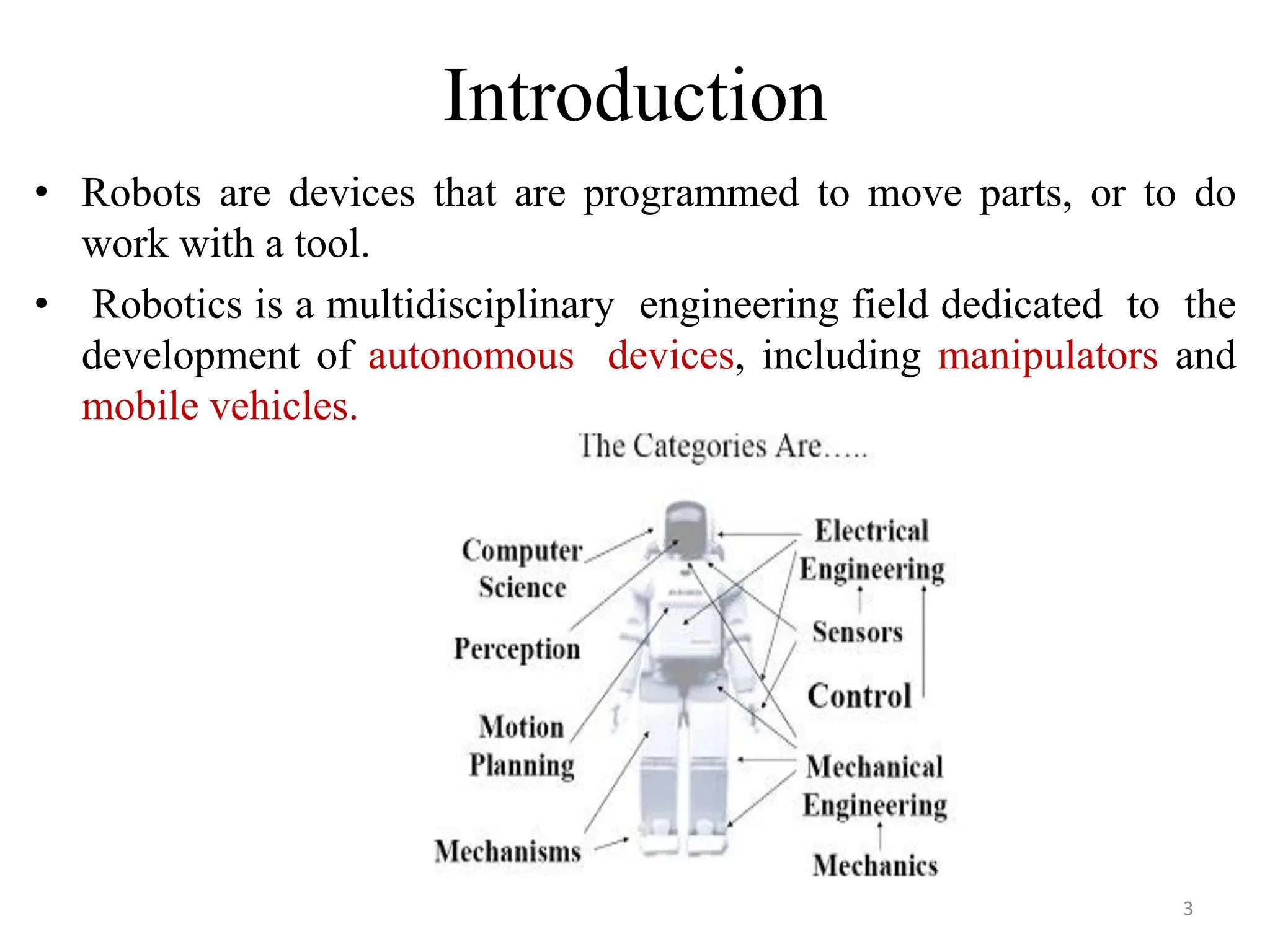
Industrial Robotics
CHAPTER 5
1
Chapter outline:
1. Introduction to Robot
2. Robotic Technology
3. Robotic programming
4. Robot Applications
2
Introduction
• Robots are devices that are programmed to move parts, or to do
work with a tool.
• Robotics is a multidisciplinary engineering field dedicated to the
development of autonomous devices, including manipulators and
mobile vehicles.
3
Cont…
• An industrial robot is a programmable, multi-
functional manipulator designed to move materials,
parts, tools, or special devices through variable
programmed motions for the performance of a variety
of tasks.
• An industrial robot consists of a mechanical
manipulator and a controller to move it and
perform other related functions.
4
Robot Anatomy
Robot anatomy usually has 3 physical configurations:-
• Body
• Arm
• Wrist
• In many industries the robots are usually stationary mounted on a
base.
• The body is attached to the base, arm is attached to the body and
wrist is attached to the arm.
• Relative motion is achieved by movements of body, arm and wrist.
5
Cont..
• Robot Joints: The joints in an industrial robot are helpful
to perform sliding and rotating movements of a
component.
• Manipulator: The manipulators in a robot are developed
by the integration of links and joints.
• Kinematics: It concerns with the assembling of robot links
and joints. It is also used to illustrate the robot motions.
6
Cont…
• Manipulator consists of joints and links
• Joints provide relative motion
• Links are rigid members between
joints
• Robot manipulator consists of two
sections:
• Body-and-arm – for positioning of
objects in the robot's work volume
• Wrist assembly – for orientation of
objects
Base
Link0
Joint1
Link2
Link3
Joint3
End of Arm
Link1
Joint2
7
Manipulator Joints
• Translational motion
• Linear joint (type L)
• Orthogonal joint (type O)
• Rotary motion
• Rotational joint (type R)
• Twisting joint (type T)
• Revolving joint (type V)
8
Robot Physical Configuration
• Industrial robots come in a variety of shapes
and sizes.
• Four basic configurations are identified with
most of the commercially available industrial
robots.
1. Cartesian Configuration
2. Cylindrical Configuration
3. Polar Configuration
4. Jointed arm Configuration
9
1. Cartesian Configuration
• Notation LOO:
• Consists of three sliding
joints, two of which are
orthogonal
• Other names include
rectilinear robot and x-y-z
robot
10
2. Cylindrical Configuration
• Notation TLO:
• Consists of a vertical
column, relative to which
an arm assembly is moved
up or down
• The arm can be moved in or
out relative to the column
11
3. Polar Configuration
• Notation TRL:
• Consists of a sliding arm (L joint) actuated relative to
the body, which can rotate about both a vertical axis (T
joint) and horizontal axis (R joint)
12
4. Jointed-Arm
• Notation TRR:
13
Basic Robot Motions
• Arm and body motions
1. Vertical traverse: Up and down motion of the arm,
2. Radial traverse: extension and retraction of the arm
(in and out movement)
3. Rotational traverse: rotation about the vertical axis
(right or left swivel of the robot arm)
• Wrist Motion
• Wrist swivel: Rotation of the wrist
• Wrist bend: Up or down movement of the wrist,
this also involves rotation movement.
• Wrist yaw: Right or left swivel of the wrist.
14
Degrees of freedom
15
Motion System
• Point to point control Robot
• Continuous path control Robot
• Controlled Path Robot
16
Specifications of Industrial Robot
• Degree of freedom
• Work space
• Precision Movement
1. Control Resolution
2. Accuracy
3. Repeatability
• Speed
• Pay Load
17
Workspace
• The robot tends to have a fixed and limited
geometry.
• The work envelope is the boundary of positions
in space that the robot can reach.
18
Other Specifications
• Payload (kg) – maximum load or carrying capacity, including weight of the end
effector.
• Reach (mm) – the maximum distance a robot can extend its arm to perform a
task.
• Speed (mm/sec) – how fast a robot can position its end effector or rotate an axis
(deg/sec).
• Acceleration (mm/sec) – defines how quickly an axis can accelerate to top
speed.
• Accuracy (± mm) – how closely a robot can move to specified place in the
work envelope.
• Repeatability (± mm) – how precisely a robot can return repeatedly to a given
position.
• Mounting– robots can also be ceiling or wall mounted, freeing up effective
workspace.
• Footprint(m2) – installation space required, often minimized by overhead or
wall mounting.
• Cycle Time(secs) – cumulative time for completing one full set of process
operations
19
Robot Control Systems
• Limited sequence control – pick-and-place operations using
mechanical stops to set positions
• Playback with point-to-point control – records work cycle as a
sequence of points, then plays back the sequence during program
execution
• Playback with continuous path control – greater memory
capacity and/or interpolation capability to execute paths (in addition
to points)
• Intelligent control – exhibits behavior that makes it seem
intelligent, e.g., responds to sensor inputs, makes decisions,
communicates with humans
20
Robot Control System
Joint 1 Joint 2 Joint 3 Joint 4 Joint 5 Joint 6
Controller
& Program
Cell
Supervisor
Sensors Level 0
Level 1
Level 2
21
End Effectors
• The special tooling for a robot that enables
it to perform a specific task
• Two types:
• Grippers – to grasp and manipulate objects
(e.g., parts) during work cycle.
• Tools – to perform a process, e.g., spot
welding, spray painting.
22
Grippers
• Grippers are end effectors used to grasp and
manipulate objects during the work cycle.
• Mechanical grippers, consisting of two or more
fingers that can be actuated by the robot controller
to open and close to grasp the work part.
• Vacuum grippers, in which suction cups are used
to hold flat objects. 23
Grippers
• Adhesive devices, where an adhesive substance
is used to hold a flexible material such as a
fabric
• Simple mechanical devices such as hooks and
scoops. Mechanical grippers are the most
common gripper type.
24
Grippers
25
Tools
• Tools are used in applications where the robot
must perform some processing operation on the
work part.
• Examples of the tools used as end effectors by
robots to perform processing applications include:
• spot welding gun
• arc welding tool
• spray painting gun, heating torch, water jet cutting
tool
• rotating spindle for drilling, routing. grinding, and so
forth
• Assembly tool (e.g., automatic screwdriver).
26
Tools
27
Sensors in robotics
• For certain robot application, the type of
workstation control using interlocks is not
adequate the robot must take on more human like
senses and capabilities in order to perform the task in
a satisfactory way these senses and capability
includes vision and hand eye coordination, touch,
hearing.
• Accordingly we will dived the types of sensors used
in robotics into the following three categories.
1. Vision sensors
2. Tactile and proximity sensors
3. Voice sensors 28
Vision Sensors
• Robot vision is made possible by means of
video camera a sufficient light source and a
computer programmed to process image data.
• Vision capability would enable the robot to carry
out the following kinds of operations.
• Retrieve parts which are randomly oriented on a
conveyor
• Recognize particular parts which are intermixed with
other objects
• Perform assembly operations which require alignment
29
Tactile and proximity sensor
• Tactile sensors provide the robot with the
capability to respond to contact forces between
itself and other objects within its work volume.
• Tactile sensors can be divided into two types:
1. Touch sensors
2. Stress sensors
• Touch sensors are used simply to indicate whether
contact has been made with an object.
• Stress sensors are used to measure the magnitude
of the contact force.
30
Voice Sensors
• Another area of robotics research is voice
sensing or voice programming.
• Voice programming can be defined as the oral
communication of commands to the robot or other
machine.
• The robot controller is equipped with a speech
recognition system which analyzes the voice
input and compares it with a set of stored word
patterns.
• Voice sensors could be useful in robot
programming to speed up the programming
procedure just as it does in NC programming31
ROBOT PROGRAMMING
• There are various methods which robots can be
programmed to perform a given work cycle.
• We divide this programming method into four
categories.
1. Manual method
2. Walkthrough method
3. Lead through method
4. Off-line programming
Manual method:
• This method is not really programming in the
conventional sense of the world.
• It is more like setting up a machine rather than
programming.
32
cont..
Walkthrough method:
• In this method the programmer manually moves the
robots arm and hand through the motion sequence of
the work cycle.
• Each movement is recorded into memory for
subsequent playback during production.
Lead through method:
• The lead through method makes use of a teach
pendant to power drive the robot through its motion
sequence.
• The teach pendant is usually a small hand held device
with switches and dials to control the robots physical
movements.
33
cont…
Off- line programming:
• This method involves the preparation of the robot program
off-line, in a manner similar to NC part programming.
• Off-line robot programming is typically accomplished on a
computer terminal.
• After the program has been prepared, it is entered in to the
robot memory for use during the work cycle.
• The advantaged of off-line robot programming is that the
production time of the robot is not lost to delay in teaching
the robot a new task.
• Programming off-line can be done while the robot is still in
production on the preceding job. This means higher
utilization of the robot and the equipment with which it
operates.
34
Industrial Robot Applications
1. Material handling applications
– Material transfer – pick-and-place, palletizing
– Machine loading and/or unloading
2. Processing operations
– Welding
– Spray coating
– Cutting and grinding
3. Assembly and inspection
35
36

Industrial Robotics in manufacturing industry

  • 1.
  • 2.
    Chapter outline: 1. Introductionto Robot 2. Robotic Technology 3. Robotic programming 4. Robot Applications 2
  • 3.
    Introduction • Robots aredevices that are programmed to move parts, or to do work with a tool. • Robotics is a multidisciplinary engineering field dedicated to the development of autonomous devices, including manipulators and mobile vehicles. 3
  • 4.
    Cont… • An industrialrobot is a programmable, multi- functional manipulator designed to move materials, parts, tools, or special devices through variable programmed motions for the performance of a variety of tasks. • An industrial robot consists of a mechanical manipulator and a controller to move it and perform other related functions. 4
  • 5.
    Robot Anatomy Robot anatomyusually has 3 physical configurations:- • Body • Arm • Wrist • In many industries the robots are usually stationary mounted on a base. • The body is attached to the base, arm is attached to the body and wrist is attached to the arm. • Relative motion is achieved by movements of body, arm and wrist. 5
  • 6.
    Cont.. • Robot Joints:The joints in an industrial robot are helpful to perform sliding and rotating movements of a component. • Manipulator: The manipulators in a robot are developed by the integration of links and joints. • Kinematics: It concerns with the assembling of robot links and joints. It is also used to illustrate the robot motions. 6
  • 7.
    Cont… • Manipulator consistsof joints and links • Joints provide relative motion • Links are rigid members between joints • Robot manipulator consists of two sections: • Body-and-arm – for positioning of objects in the robot's work volume • Wrist assembly – for orientation of objects Base Link0 Joint1 Link2 Link3 Joint3 End of Arm Link1 Joint2 7
  • 8.
    Manipulator Joints • Translationalmotion • Linear joint (type L) • Orthogonal joint (type O) • Rotary motion • Rotational joint (type R) • Twisting joint (type T) • Revolving joint (type V) 8
  • 9.
    Robot Physical Configuration •Industrial robots come in a variety of shapes and sizes. • Four basic configurations are identified with most of the commercially available industrial robots. 1. Cartesian Configuration 2. Cylindrical Configuration 3. Polar Configuration 4. Jointed arm Configuration 9
  • 10.
    1. Cartesian Configuration •Notation LOO: • Consists of three sliding joints, two of which are orthogonal • Other names include rectilinear robot and x-y-z robot 10
  • 11.
    2. Cylindrical Configuration •Notation TLO: • Consists of a vertical column, relative to which an arm assembly is moved up or down • The arm can be moved in or out relative to the column 11
  • 12.
    3. Polar Configuration •Notation TRL: • Consists of a sliding arm (L joint) actuated relative to the body, which can rotate about both a vertical axis (T joint) and horizontal axis (R joint) 12
  • 13.
  • 14.
    Basic Robot Motions •Arm and body motions 1. Vertical traverse: Up and down motion of the arm, 2. Radial traverse: extension and retraction of the arm (in and out movement) 3. Rotational traverse: rotation about the vertical axis (right or left swivel of the robot arm) • Wrist Motion • Wrist swivel: Rotation of the wrist • Wrist bend: Up or down movement of the wrist, this also involves rotation movement. • Wrist yaw: Right or left swivel of the wrist. 14
  • 15.
  • 16.
    Motion System • Pointto point control Robot • Continuous path control Robot • Controlled Path Robot 16
  • 17.
    Specifications of IndustrialRobot • Degree of freedom • Work space • Precision Movement 1. Control Resolution 2. Accuracy 3. Repeatability • Speed • Pay Load 17
  • 18.
    Workspace • The robottends to have a fixed and limited geometry. • The work envelope is the boundary of positions in space that the robot can reach. 18
  • 19.
    Other Specifications • Payload(kg) – maximum load or carrying capacity, including weight of the end effector. • Reach (mm) – the maximum distance a robot can extend its arm to perform a task. • Speed (mm/sec) – how fast a robot can position its end effector or rotate an axis (deg/sec). • Acceleration (mm/sec) – defines how quickly an axis can accelerate to top speed. • Accuracy (± mm) – how closely a robot can move to specified place in the work envelope. • Repeatability (± mm) – how precisely a robot can return repeatedly to a given position. • Mounting– robots can also be ceiling or wall mounted, freeing up effective workspace. • Footprint(m2) – installation space required, often minimized by overhead or wall mounting. • Cycle Time(secs) – cumulative time for completing one full set of process operations 19
  • 20.
    Robot Control Systems •Limited sequence control – pick-and-place operations using mechanical stops to set positions • Playback with point-to-point control – records work cycle as a sequence of points, then plays back the sequence during program execution • Playback with continuous path control – greater memory capacity and/or interpolation capability to execute paths (in addition to points) • Intelligent control – exhibits behavior that makes it seem intelligent, e.g., responds to sensor inputs, makes decisions, communicates with humans 20
  • 21.
    Robot Control System Joint1 Joint 2 Joint 3 Joint 4 Joint 5 Joint 6 Controller & Program Cell Supervisor Sensors Level 0 Level 1 Level 2 21
  • 22.
    End Effectors • Thespecial tooling for a robot that enables it to perform a specific task • Two types: • Grippers – to grasp and manipulate objects (e.g., parts) during work cycle. • Tools – to perform a process, e.g., spot welding, spray painting. 22
  • 23.
    Grippers • Grippers areend effectors used to grasp and manipulate objects during the work cycle. • Mechanical grippers, consisting of two or more fingers that can be actuated by the robot controller to open and close to grasp the work part. • Vacuum grippers, in which suction cups are used to hold flat objects. 23
  • 24.
    Grippers • Adhesive devices,where an adhesive substance is used to hold a flexible material such as a fabric • Simple mechanical devices such as hooks and scoops. Mechanical grippers are the most common gripper type. 24
  • 25.
  • 26.
    Tools • Tools areused in applications where the robot must perform some processing operation on the work part. • Examples of the tools used as end effectors by robots to perform processing applications include: • spot welding gun • arc welding tool • spray painting gun, heating torch, water jet cutting tool • rotating spindle for drilling, routing. grinding, and so forth • Assembly tool (e.g., automatic screwdriver). 26
  • 27.
  • 28.
    Sensors in robotics •For certain robot application, the type of workstation control using interlocks is not adequate the robot must take on more human like senses and capabilities in order to perform the task in a satisfactory way these senses and capability includes vision and hand eye coordination, touch, hearing. • Accordingly we will dived the types of sensors used in robotics into the following three categories. 1. Vision sensors 2. Tactile and proximity sensors 3. Voice sensors 28
  • 29.
    Vision Sensors • Robotvision is made possible by means of video camera a sufficient light source and a computer programmed to process image data. • Vision capability would enable the robot to carry out the following kinds of operations. • Retrieve parts which are randomly oriented on a conveyor • Recognize particular parts which are intermixed with other objects • Perform assembly operations which require alignment 29
  • 30.
    Tactile and proximitysensor • Tactile sensors provide the robot with the capability to respond to contact forces between itself and other objects within its work volume. • Tactile sensors can be divided into two types: 1. Touch sensors 2. Stress sensors • Touch sensors are used simply to indicate whether contact has been made with an object. • Stress sensors are used to measure the magnitude of the contact force. 30
  • 31.
    Voice Sensors • Anotherarea of robotics research is voice sensing or voice programming. • Voice programming can be defined as the oral communication of commands to the robot or other machine. • The robot controller is equipped with a speech recognition system which analyzes the voice input and compares it with a set of stored word patterns. • Voice sensors could be useful in robot programming to speed up the programming procedure just as it does in NC programming31
  • 32.
    ROBOT PROGRAMMING • Thereare various methods which robots can be programmed to perform a given work cycle. • We divide this programming method into four categories. 1. Manual method 2. Walkthrough method 3. Lead through method 4. Off-line programming Manual method: • This method is not really programming in the conventional sense of the world. • It is more like setting up a machine rather than programming. 32
  • 33.
    cont.. Walkthrough method: • Inthis method the programmer manually moves the robots arm and hand through the motion sequence of the work cycle. • Each movement is recorded into memory for subsequent playback during production. Lead through method: • The lead through method makes use of a teach pendant to power drive the robot through its motion sequence. • The teach pendant is usually a small hand held device with switches and dials to control the robots physical movements. 33
  • 34.
    cont… Off- line programming: •This method involves the preparation of the robot program off-line, in a manner similar to NC part programming. • Off-line robot programming is typically accomplished on a computer terminal. • After the program has been prepared, it is entered in to the robot memory for use during the work cycle. • The advantaged of off-line robot programming is that the production time of the robot is not lost to delay in teaching the robot a new task. • Programming off-line can be done while the robot is still in production on the preceding job. This means higher utilization of the robot and the equipment with which it operates. 34
  • 35.
    Industrial Robot Applications 1.Material handling applications – Material transfer – pick-and-place, palletizing – Machine loading and/or unloading 2. Processing operations – Welding – Spray coating – Cutting and grinding 3. Assembly and inspection 35
  • 36.