Downloaded 360 times
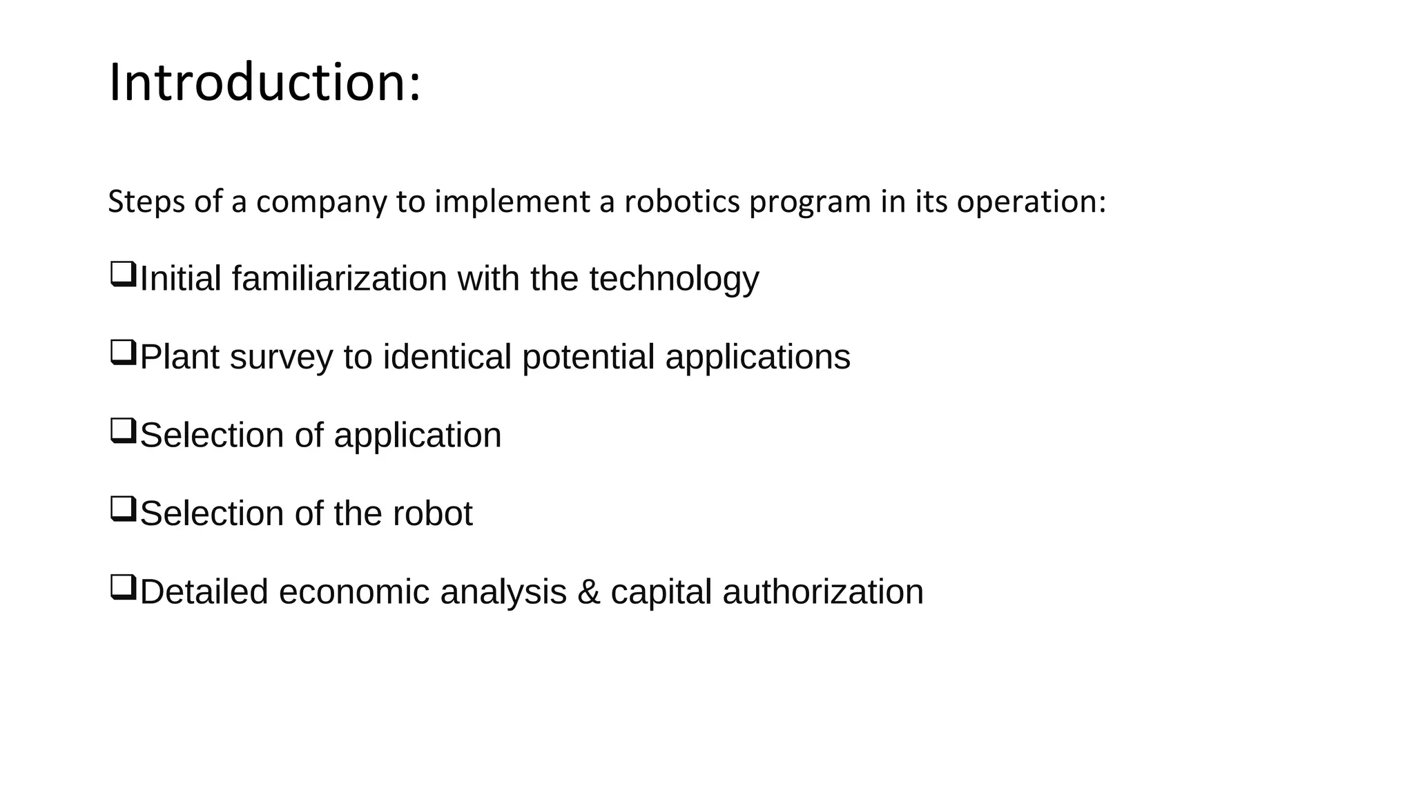
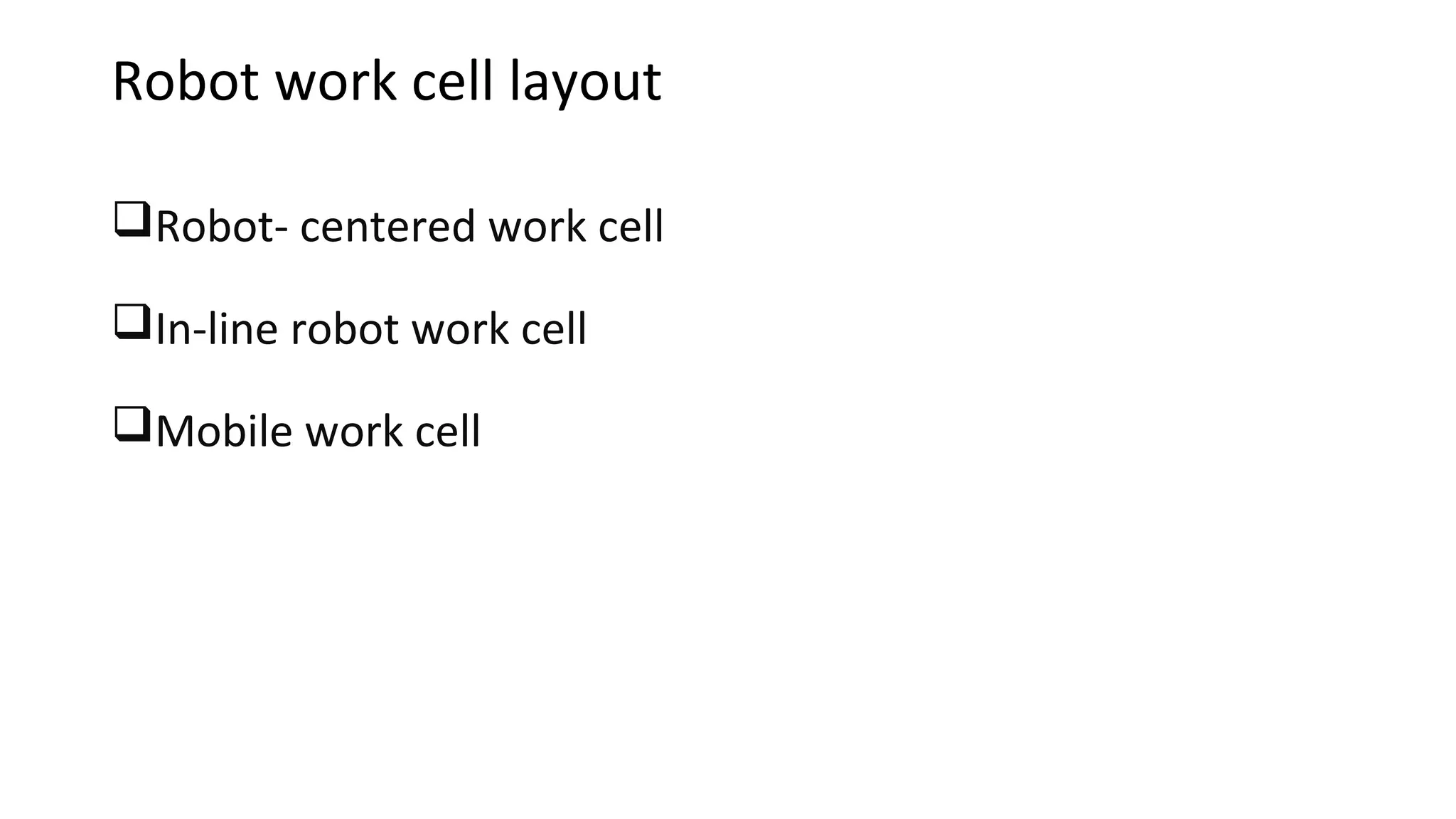
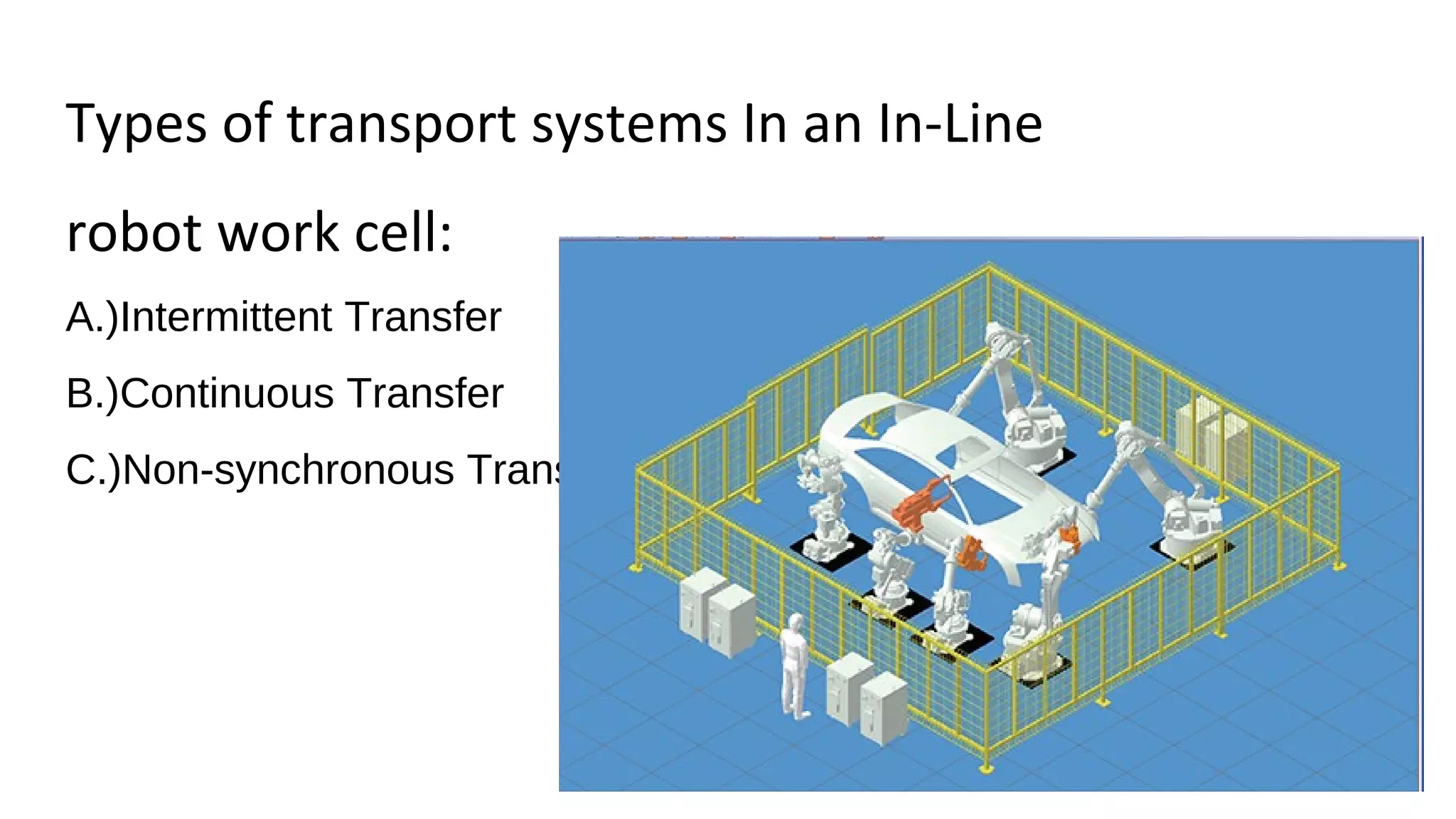
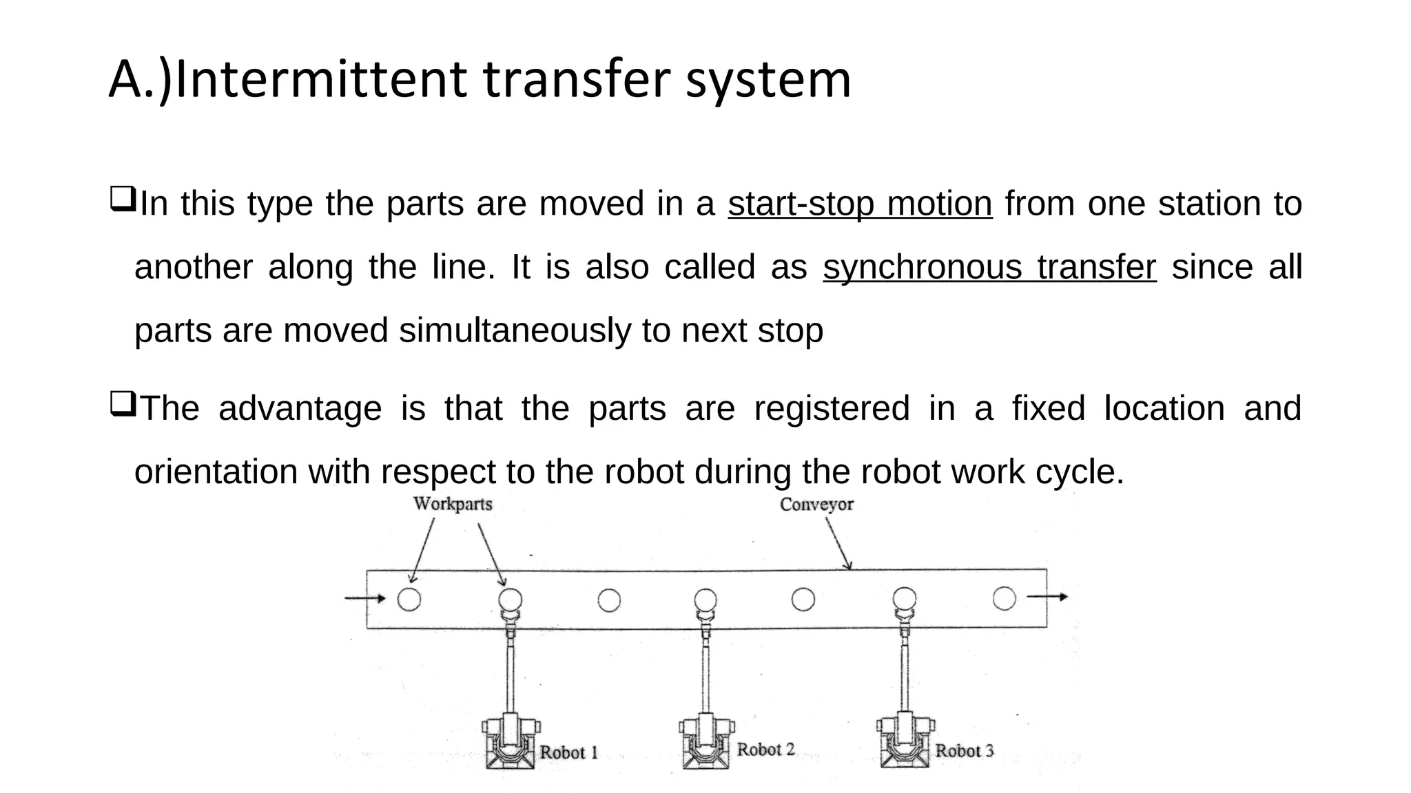
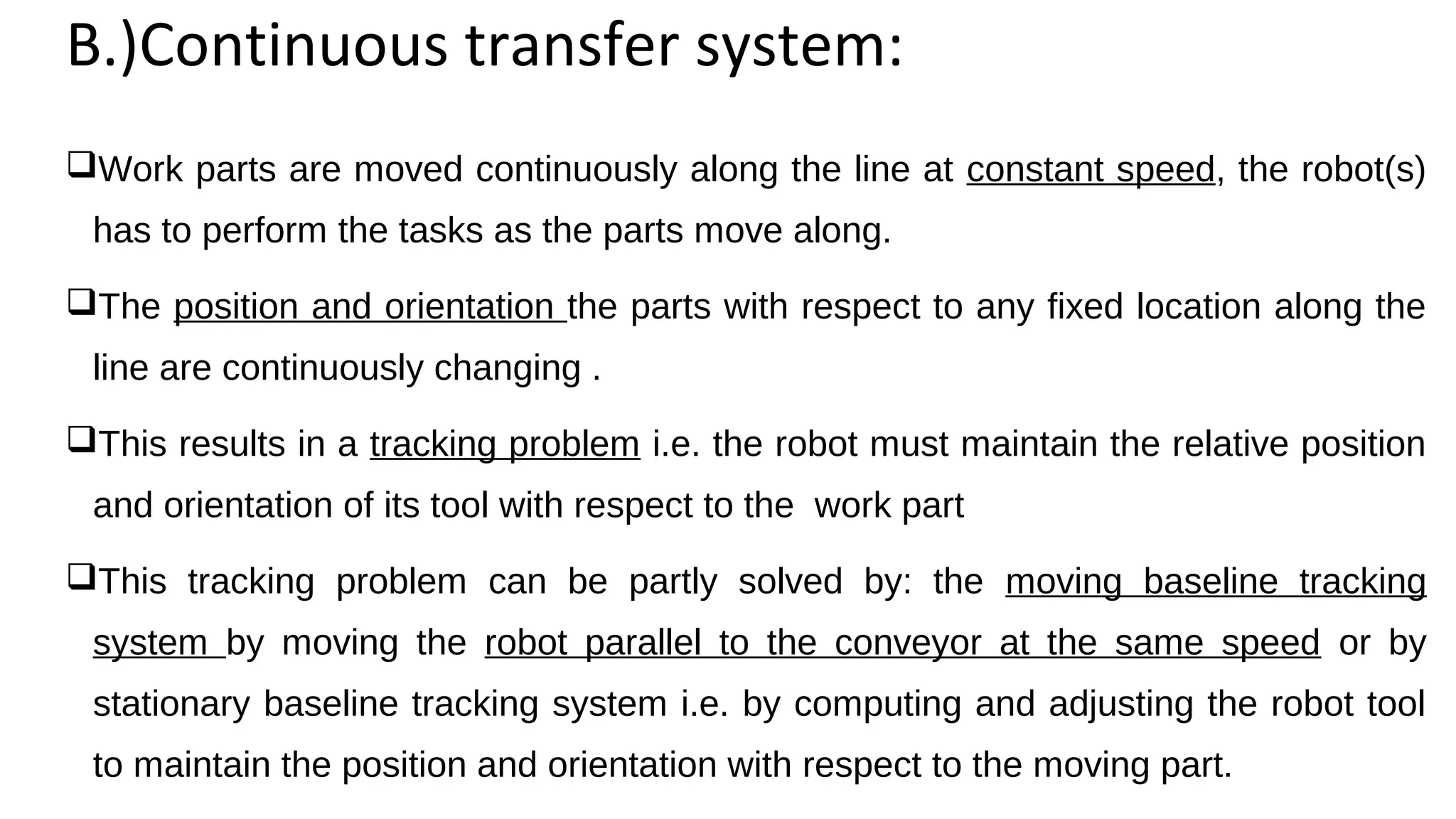
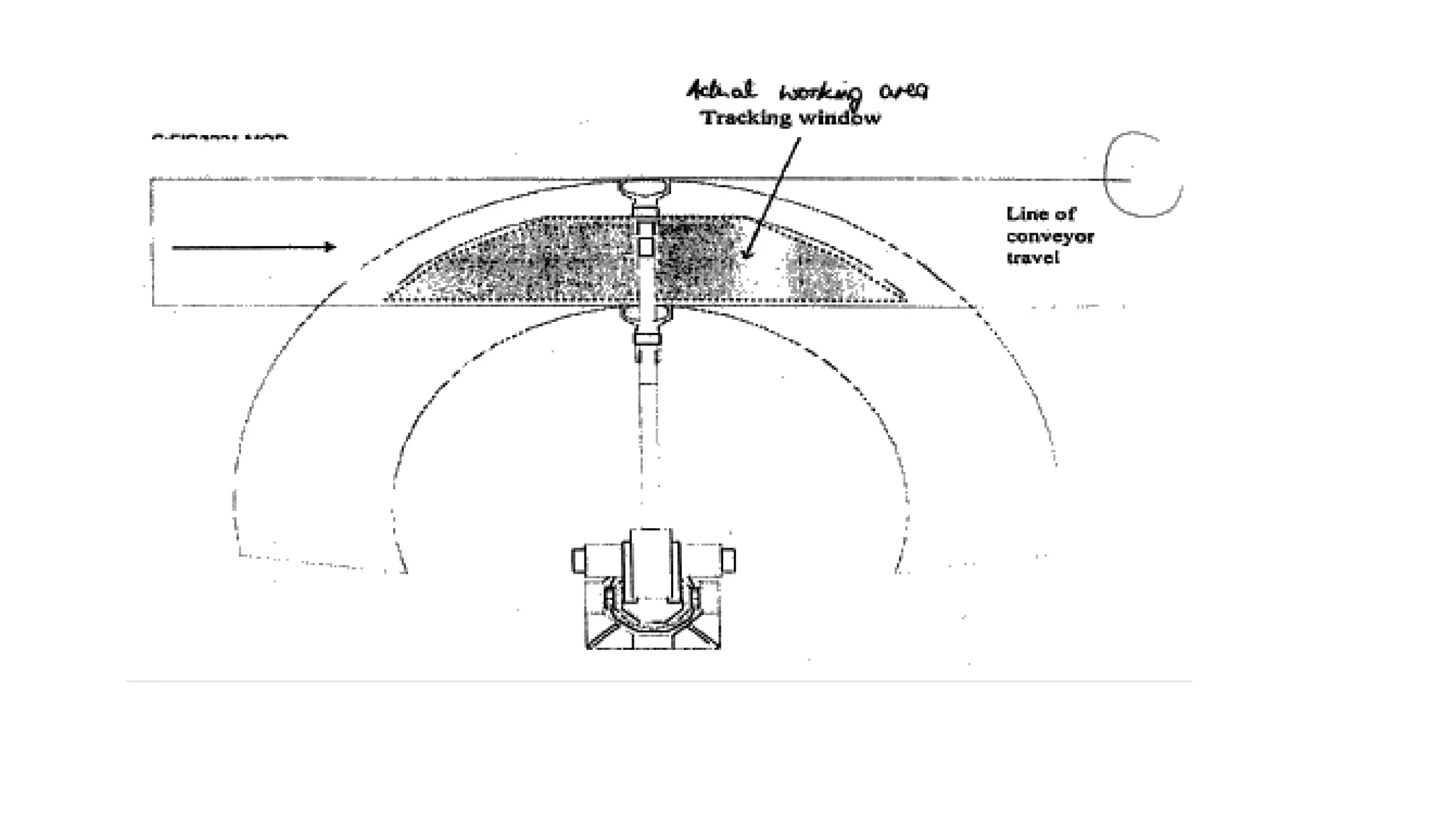

The document discusses considerations for robot cell layout design involving multiple robots and machine interfaces. It describes three common robot cell layouts: robot-centered, in-line, and mobile. For in-line cells, it discusses three types of part transfer systems and provides an example to calculate machine interference. The document also outlines several important considerations for work cell design, including modifications to equipment, part positioning, identification, protecting robots, required utilities, cell control, and safety measures.
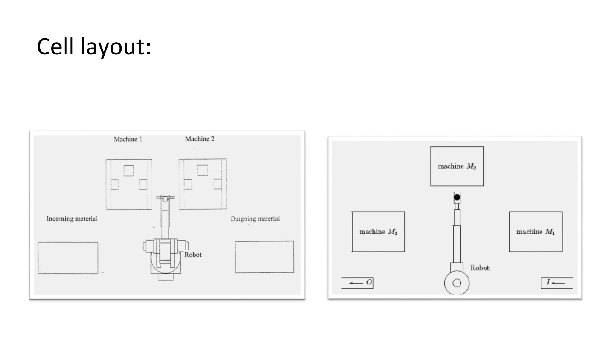
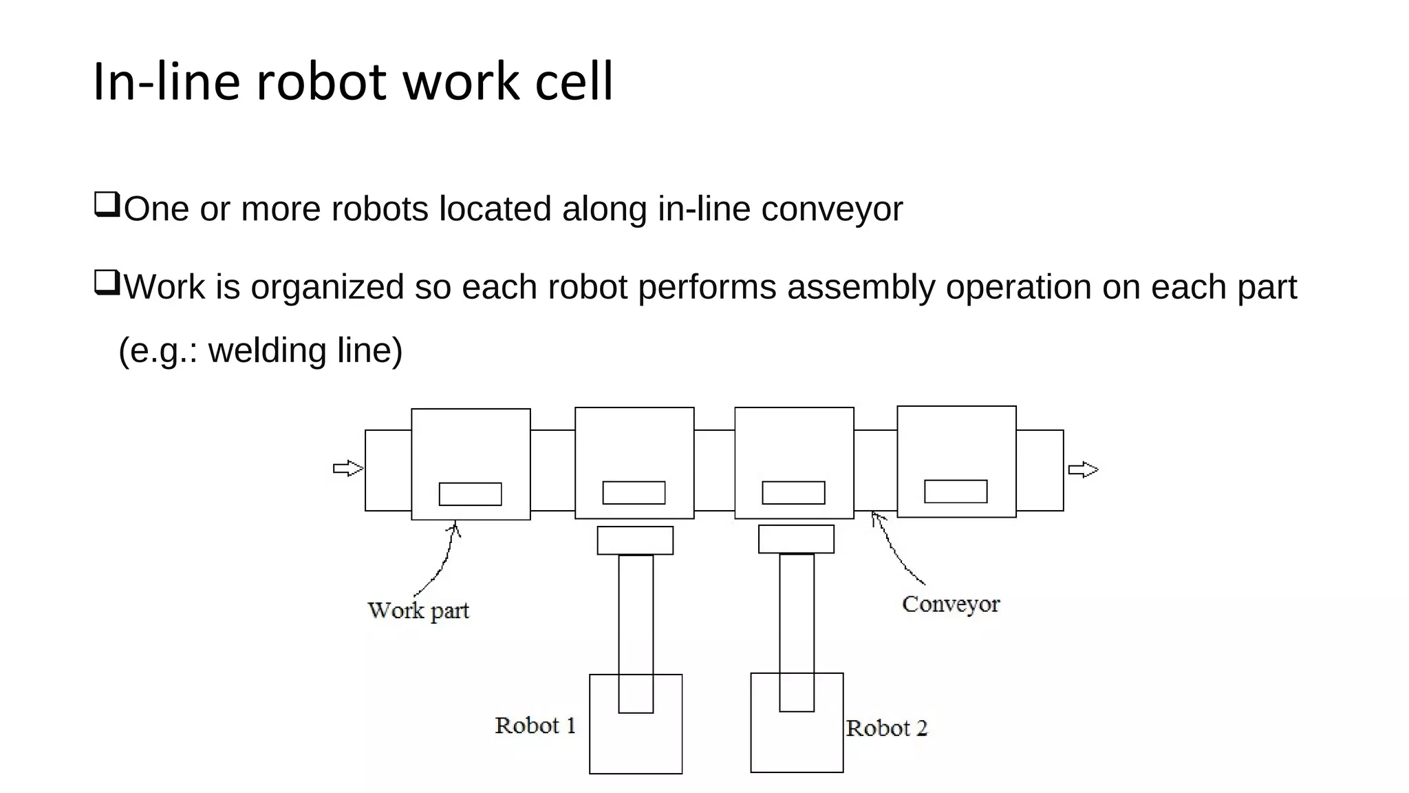
Overview of robot cell layouts and important considerations for robotics implementation and design.
Overview of robot cell layouts and important considerations for robotics implementation and design.
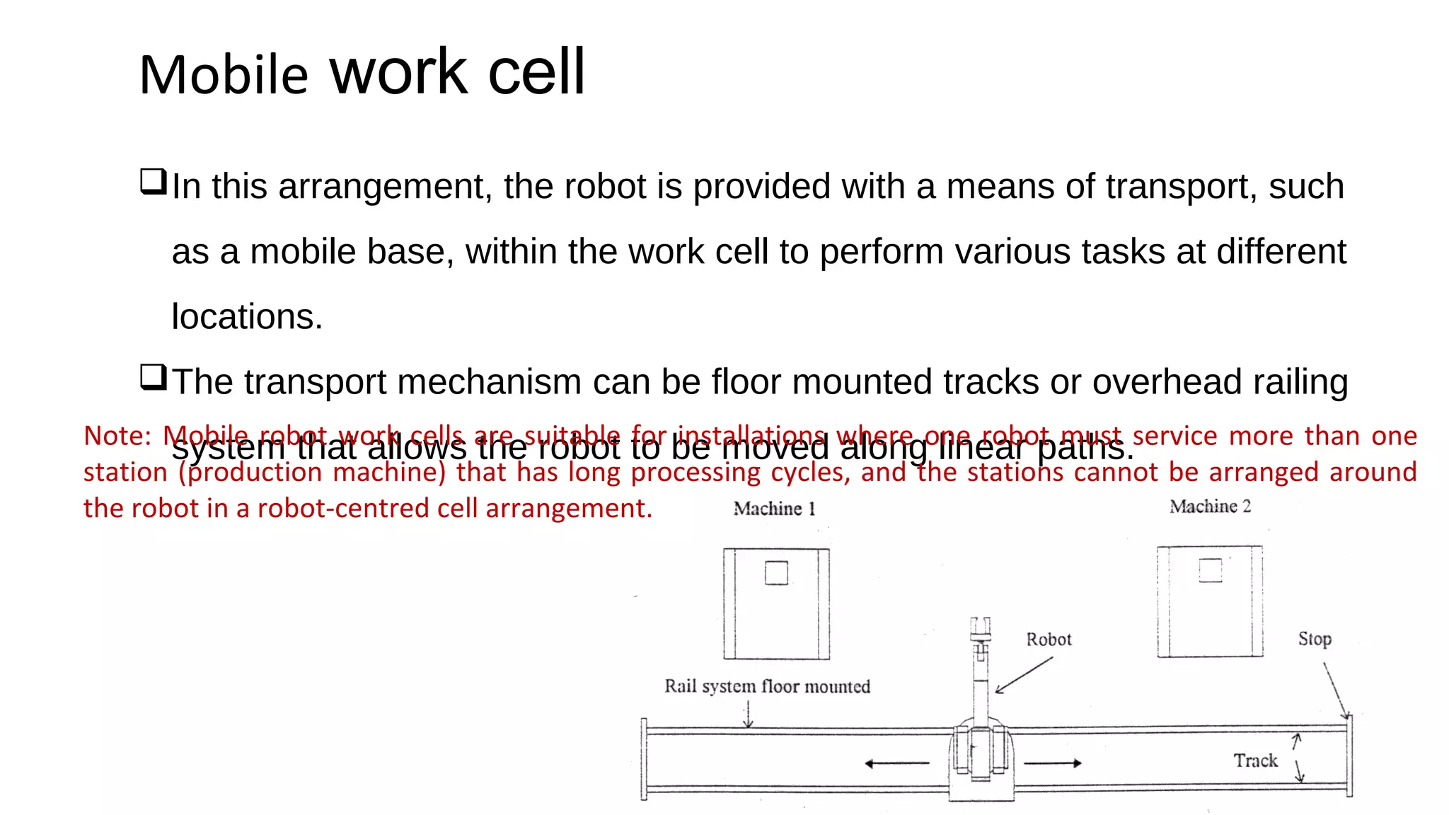
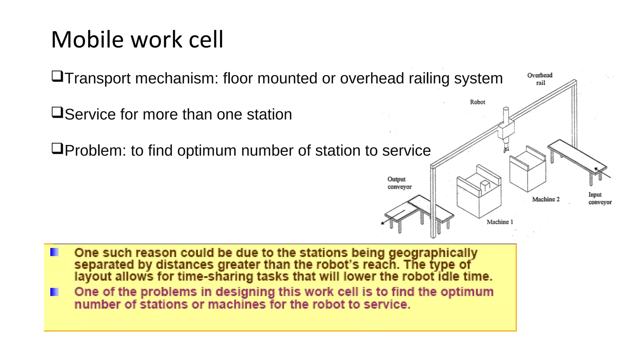
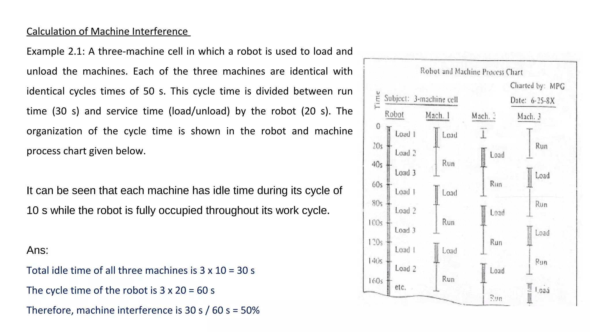
Overview of robot cell layouts and important considerations for robotics implementation and design.Explains mobile work cell setups providing flexibility by servicing multiple stations with transport mechanisms.Examination of physical and machine interference when multiple robots service machines, including calculations.
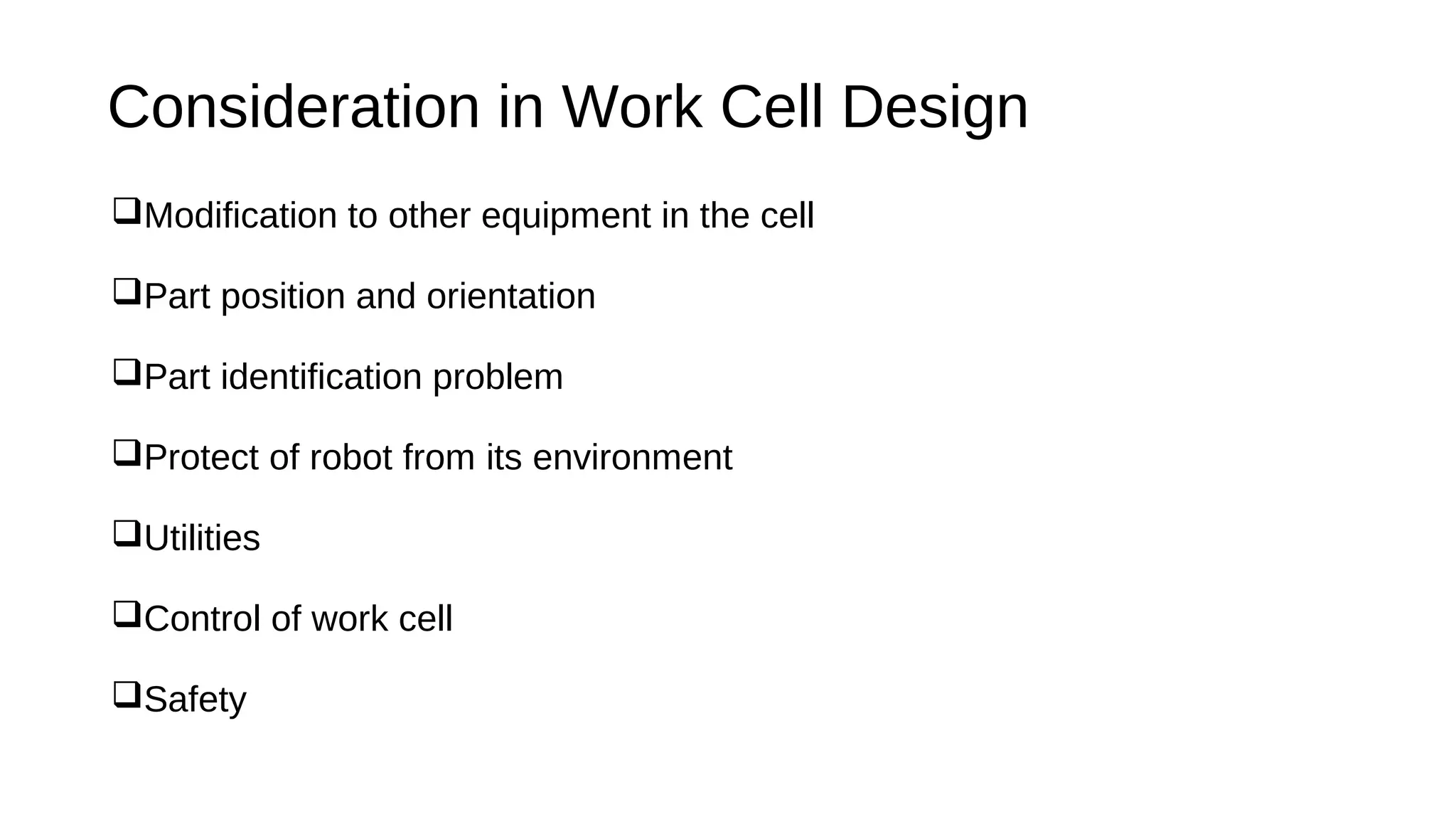
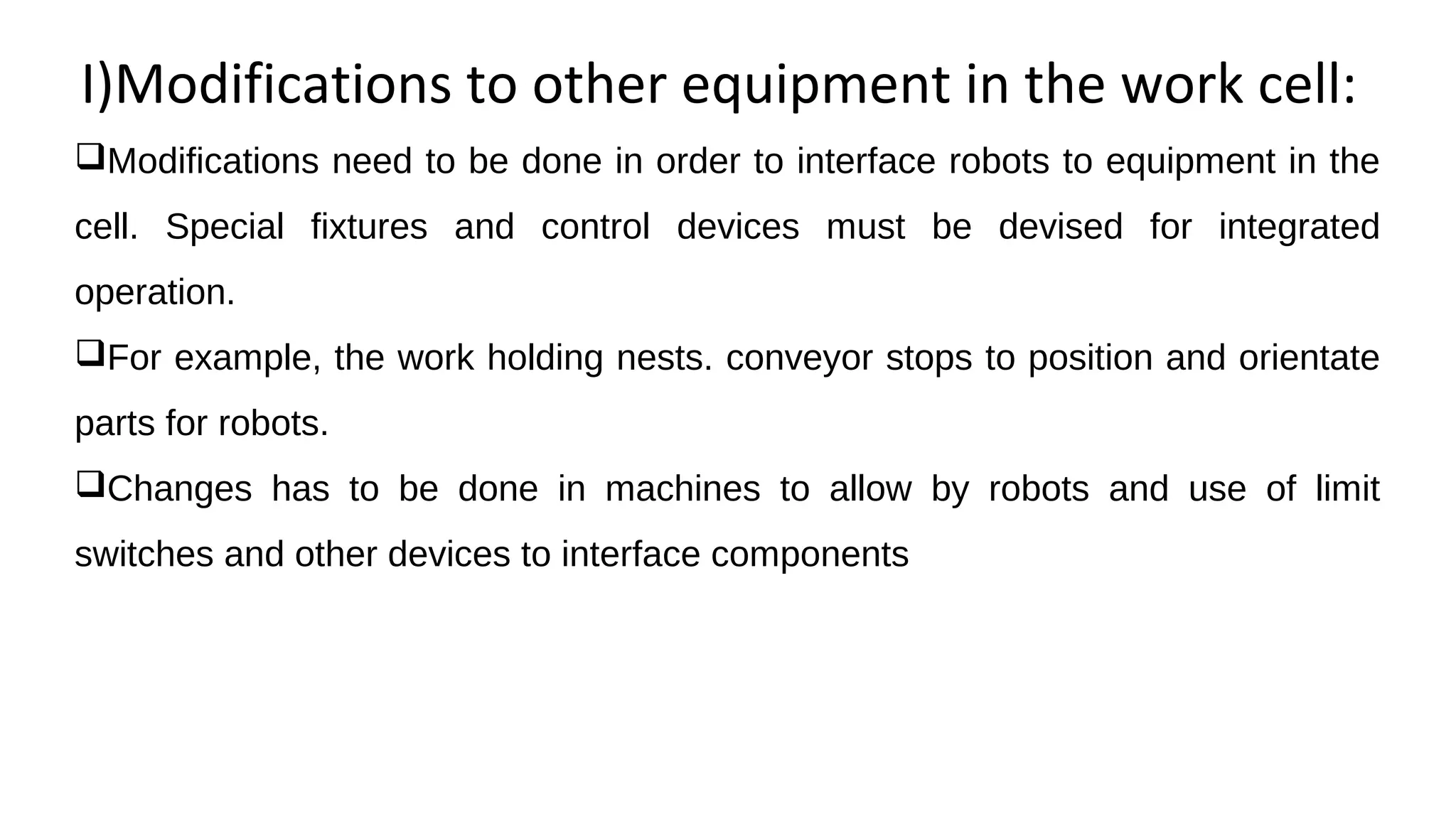
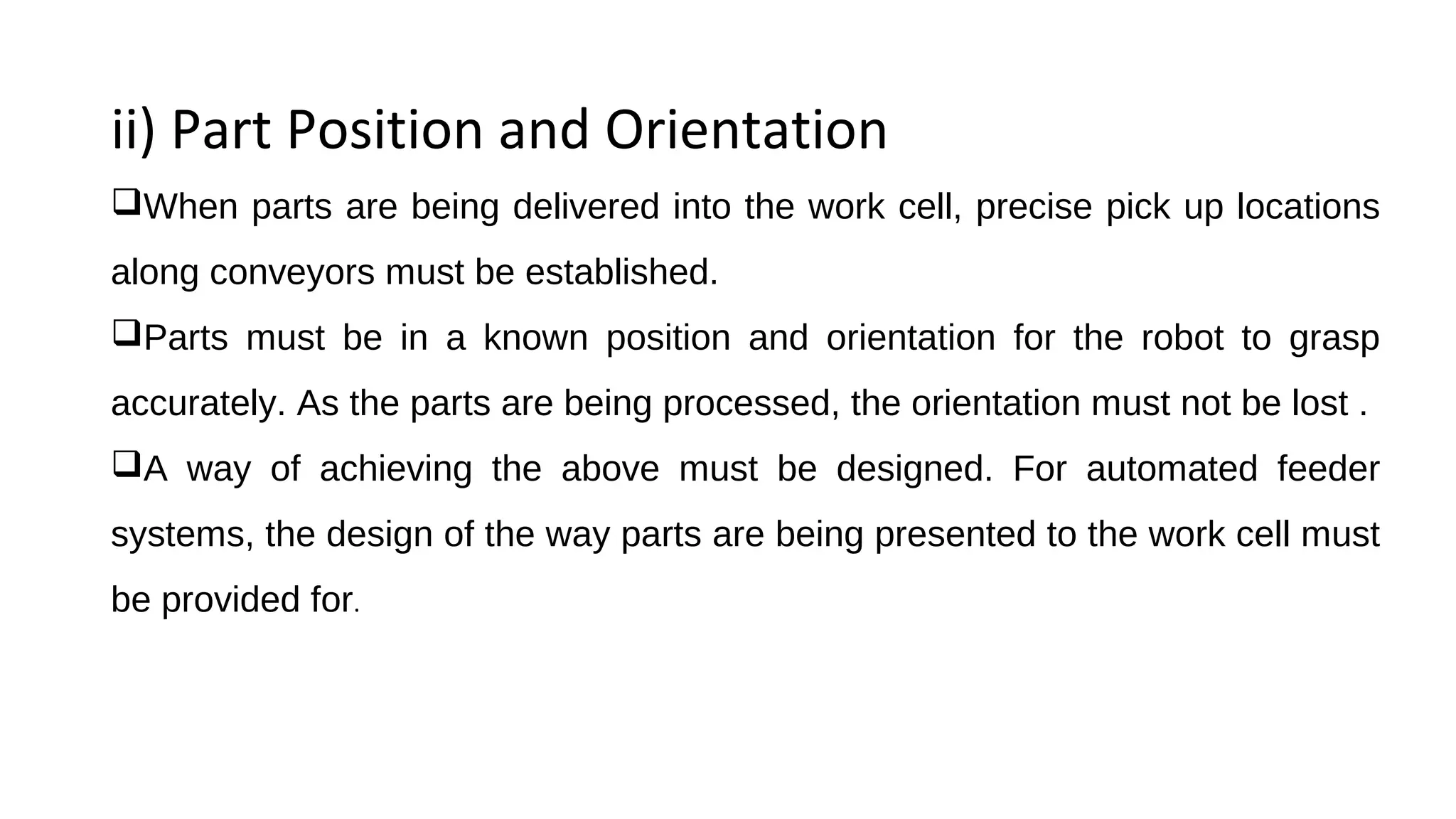
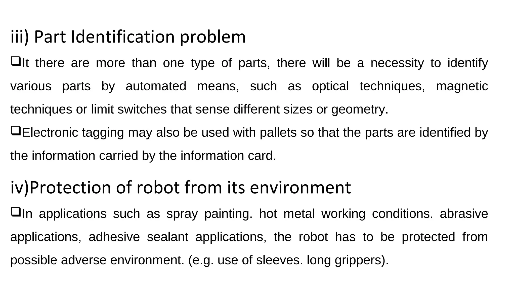
Critical aspects for work cells, such as modifications to equipment, part handling, utilities, safety measures.
Thank you note concluding the presentation.


![UNIT-5 Robot work cell layout ppt [Autosaved].pptx](https://cdn.slidesharecdn.com/ss_thumbnails/unit-5robotworkcelllayoutpptautosaved-250103014728-4471ab6d-thumbnail.jpg?width=640&height=640&fit=bounds)


