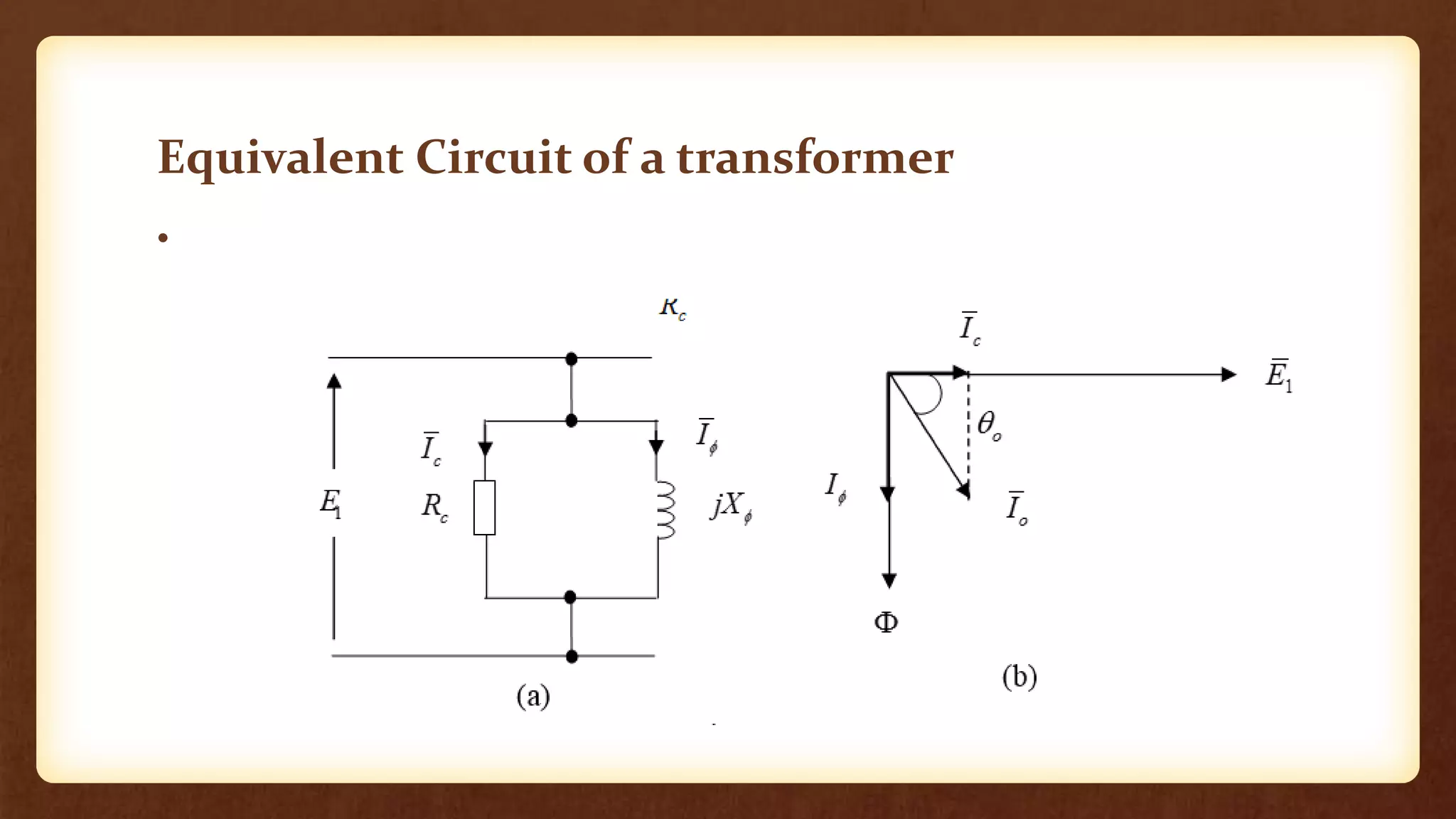
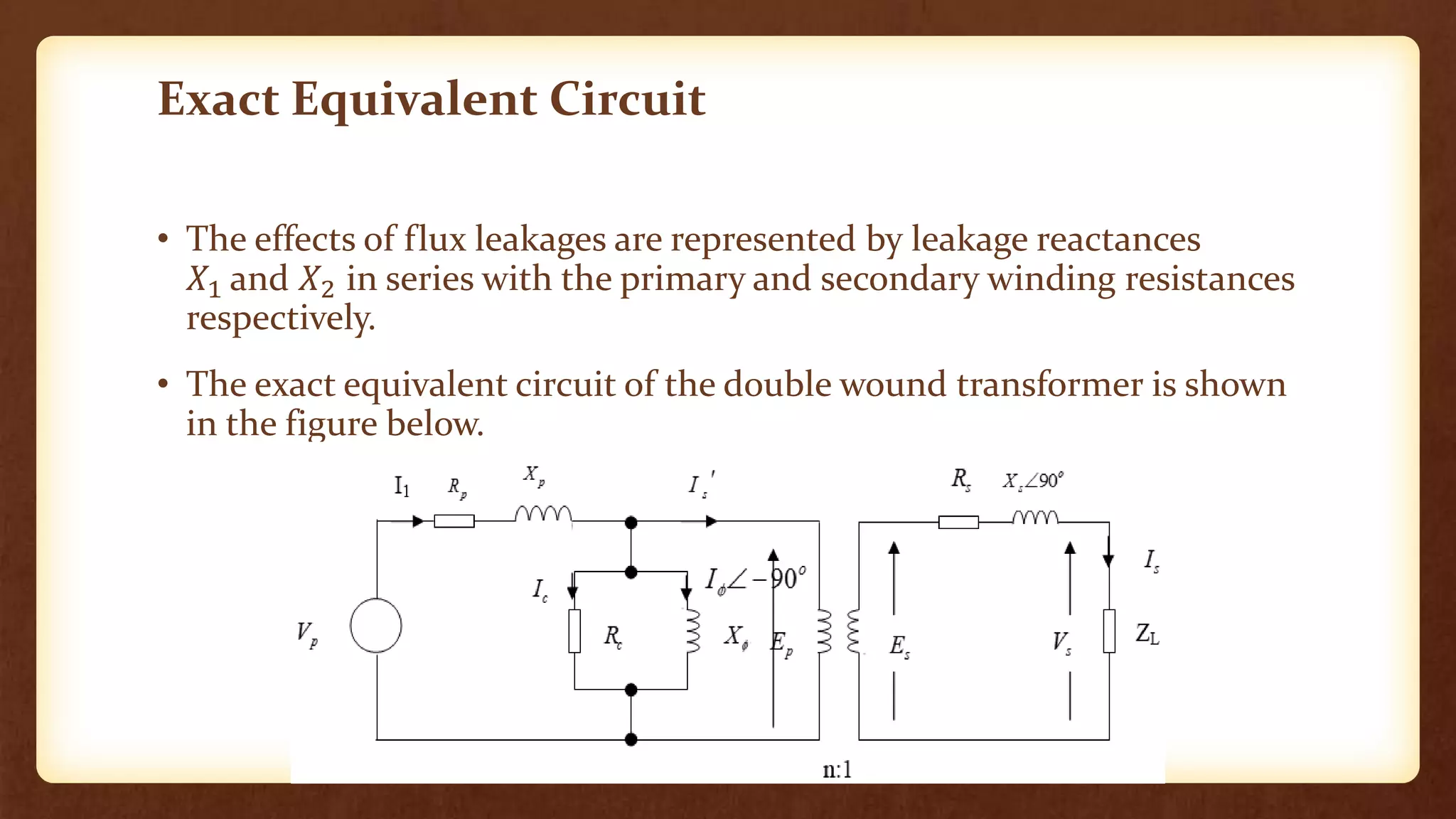
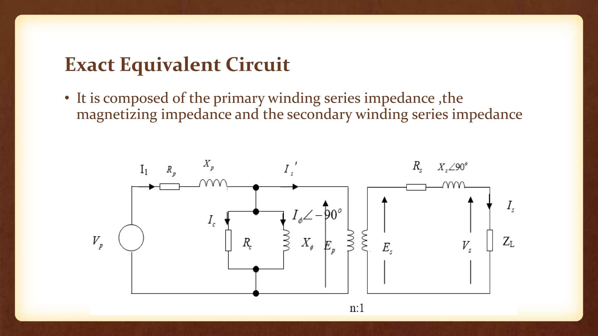
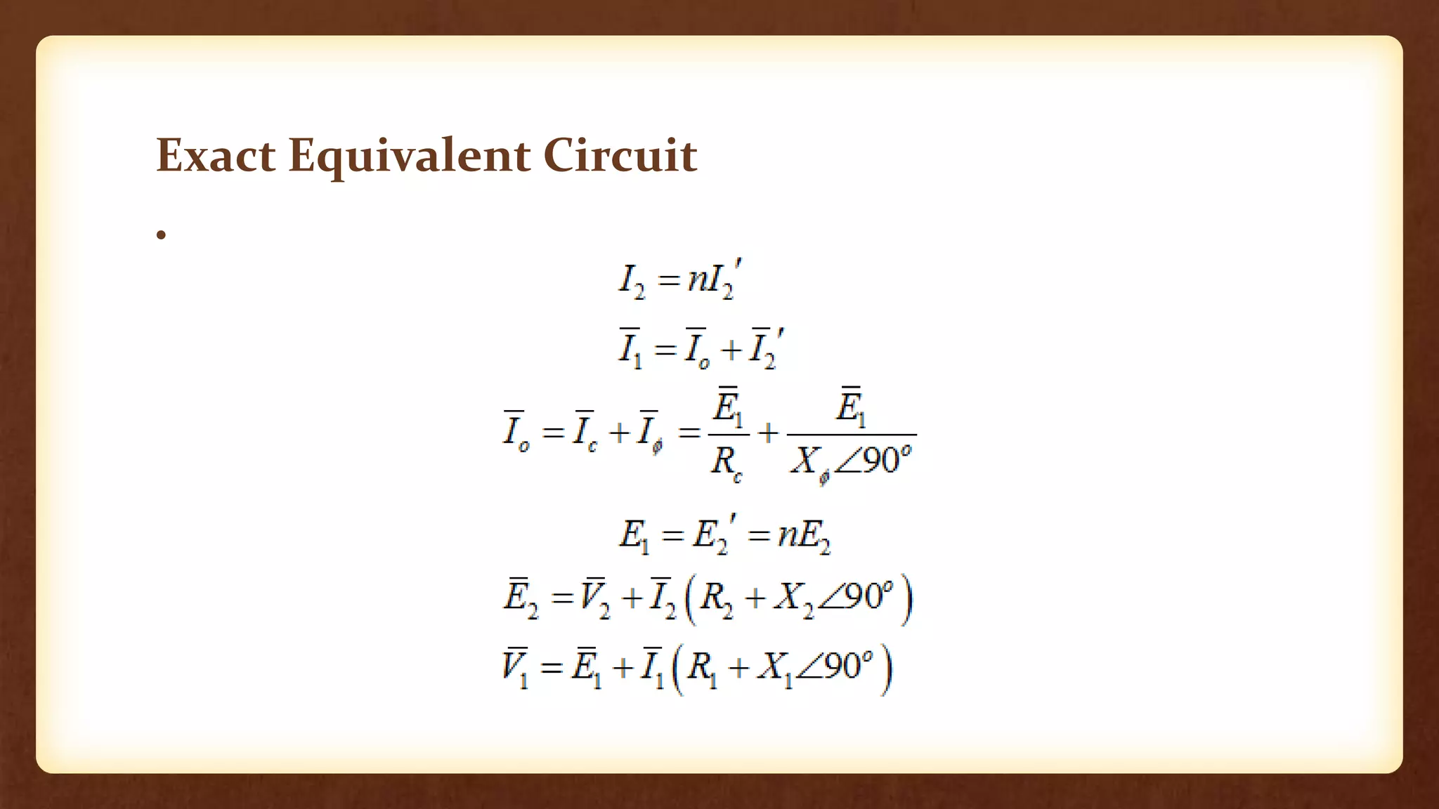
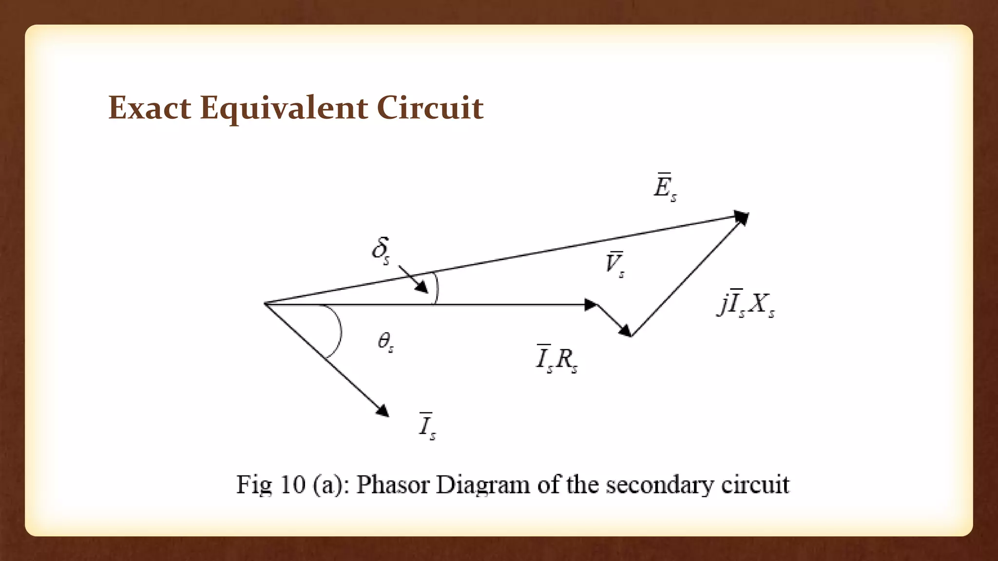
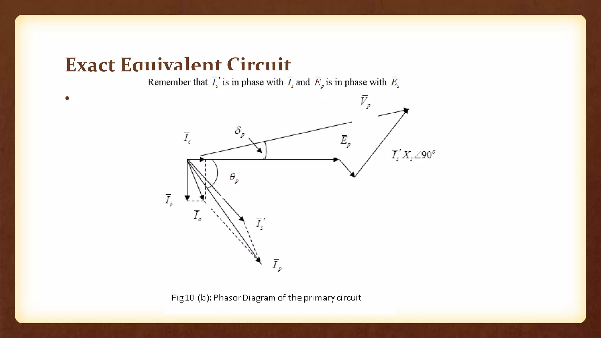
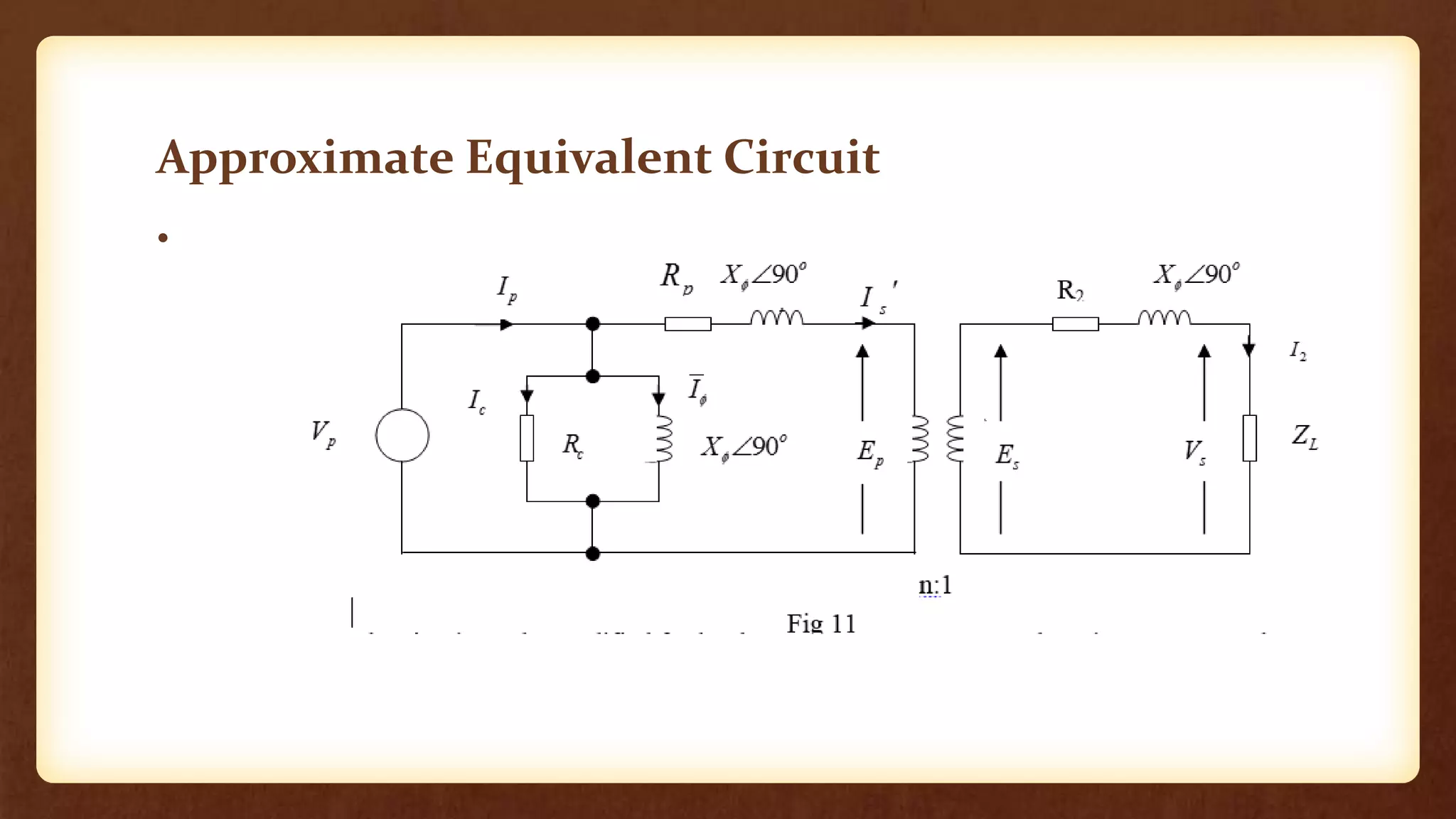
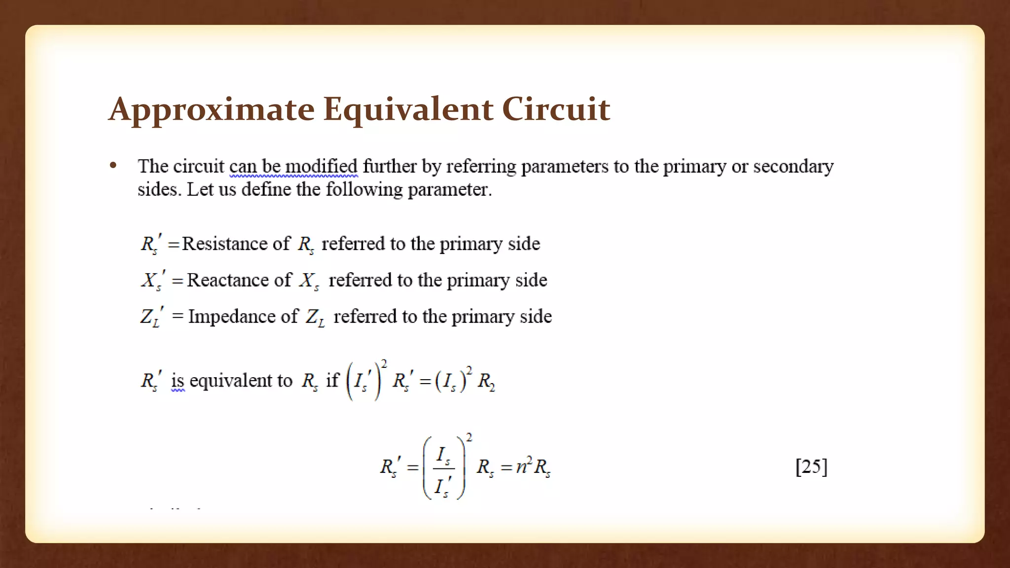
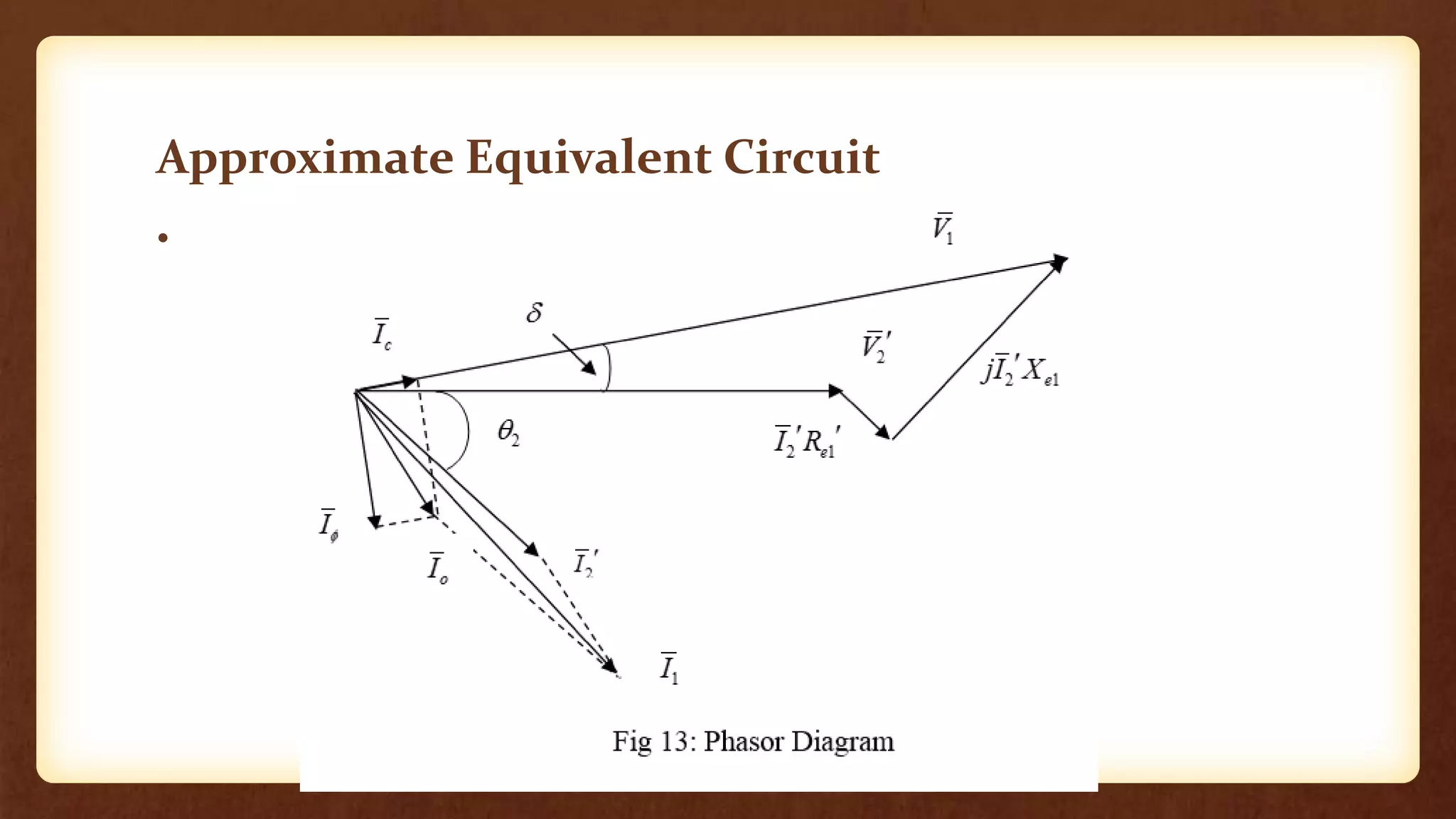
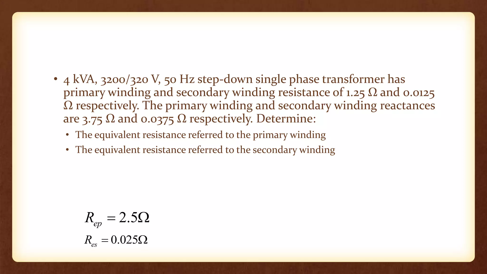
Transformers equivalent circuit
Outline
• Exact equivalent circuit
• Approximate Equivalent Circuit
Equivalent Circuit of a transformer
• The equivalent circuit enables us to analyze and predict the
performance of the transformer by using electric circuit theory.
Exact Equivalent Circuit
• At no-load the current is used to create the magnetic flux and to supply
the core losses.
• The magnetizing current lags the voltage E1 by 90o while the core loss
current is in phase with E1
• Thus the phasor diagram of the magnetizing branch is shown in Figure
Equivalent Circuit of a transformer
•
Exact Equivalent Circuit
• At no-load the effect of magnetizing the core is represented by a
fictitious inductive reactance called magnetizing reactance (𝑋Φ )
across the emf E1
𝐸1 = 𝑋Φ𝐼Φ
• Core losses are represented by a fictitious resistance called the core loss
resistance (𝑅𝑐)
Exact Equivalent Circuit
• When the transformer is on load, secondary current flows causing the
primary current to increase over the no-load current.
• In the equivalent circuit the primary and secondary winding
resistances are represented by 𝑅𝑝 and 𝑅𝑠 respectively. The
corresponding copper losses are
Exact Equivalent Circuit
• The effects of flux leakages are represented by leakage reactances
𝑋1 and 𝑋2 in series with the primary and secondary winding resistances
respectively.
• The exact equivalent circuit of the double wound transformer is shown
in the figure below.
Exact Equivalent Circuit
• It is composed of the primary winding series impedance ,the
magnetizing impedance and the secondary winding series impedance
Exact Equivalent Circuit
•
Exact Equivalent Circuit
•
Approximate Equivalent Circuit
• The circuit of Fig 9 can be simplified by connecting the magnetizing
branch across the supply to obtain the approximate equivalent circuit
shown in Fig 11.
• This increases the value of the no-load current and core losses slightly
while reducing the voltage drop across the series impedance ( ) and the
copper power loss in the primary winding slightly.
• Why?
Approximate Equivalent Circuit
•
Approximate Equivalent Circuit
•
Approximate Equivalent Circuit
•
Approximate Equivalent Circuit
•
• 4 kVA, 3200/320 V, 50 Hz step-down single phase transformer has
primary winding and secondary winding resistance of 1.25 Ω and 0.0125
Ω respectively. The primary winding and secondary winding reactances
are 3.75 Ω and 0.0375 Ω respectively. Determine:
• The equivalent resistance referred to the primary winding
• The equivalent resistance referred to the secondary winding
2.5
ep
R  
0.025
es
R  

4. Transformer equivalence circuit.pptx

  • 1.
  • 2.
    Outline • Exact equivalentcircuit • Approximate Equivalent Circuit
  • 3.
    Equivalent Circuit ofa transformer • The equivalent circuit enables us to analyze and predict the performance of the transformer by using electric circuit theory. Exact Equivalent Circuit • At no-load the current is used to create the magnetic flux and to supply the core losses. • The magnetizing current lags the voltage E1 by 90o while the core loss current is in phase with E1 • Thus the phasor diagram of the magnetizing branch is shown in Figure
  • 4.
    Equivalent Circuit ofa transformer •
  • 5.
    Exact Equivalent Circuit •At no-load the effect of magnetizing the core is represented by a fictitious inductive reactance called magnetizing reactance (𝑋Φ ) across the emf E1 𝐸1 = 𝑋Φ𝐼Φ • Core losses are represented by a fictitious resistance called the core loss resistance (𝑅𝑐)
  • 6.
    Exact Equivalent Circuit •When the transformer is on load, secondary current flows causing the primary current to increase over the no-load current. • In the equivalent circuit the primary and secondary winding resistances are represented by 𝑅𝑝 and 𝑅𝑠 respectively. The corresponding copper losses are
  • 7.
    Exact Equivalent Circuit •The effects of flux leakages are represented by leakage reactances 𝑋1 and 𝑋2 in series with the primary and secondary winding resistances respectively. • The exact equivalent circuit of the double wound transformer is shown in the figure below.
  • 8.
    Exact Equivalent Circuit •It is composed of the primary winding series impedance ,the magnetizing impedance and the secondary winding series impedance
  • 9.
  • 10.
  • 11.
  • 12.
    Approximate Equivalent Circuit •The circuit of Fig 9 can be simplified by connecting the magnetizing branch across the supply to obtain the approximate equivalent circuit shown in Fig 11. • This increases the value of the no-load current and core losses slightly while reducing the voltage drop across the series impedance ( ) and the copper power loss in the primary winding slightly. • Why?
  • 13.
  • 14.
  • 15.
  • 16.
  • 17.
  • 18.
  • 19.
  • 20.
    • 4 kVA,3200/320 V, 50 Hz step-down single phase transformer has primary winding and secondary winding resistance of 1.25 Ω and 0.0125 Ω respectively. The primary winding and secondary winding reactances are 3.75 Ω and 0.0375 Ω respectively. Determine: • The equivalent resistance referred to the primary winding • The equivalent resistance referred to the secondary winding 2.5 ep R   0.025 es R  