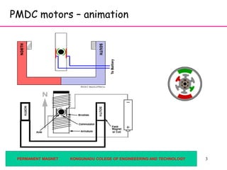
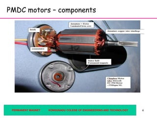
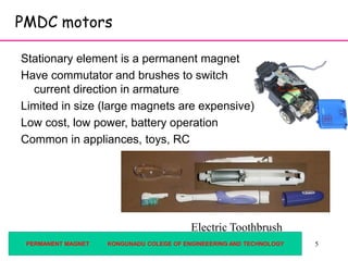
1PERMANENT MAGNET KONGUNADU COLEGE OF ENGINEEERING AND TECHNOLOGY
PMDC MOTORS
Content:
 Introduction to PMDC motors and types.
 Working principle
 Efficiency calculation with graph.
 References
22
Permanent magnet (PM) DC motors
Armature
Permanent Magnets
Brushes
Commutator Coils
PERMANENT MAGNET KONGUNADU COLEGE OF ENGINEEERING AND TECHNOLOGY
3
PMDC motors – animation
PERMANENT MAGNET KONGUNADU COLEGE OF ENGINEEERING AND TECHNOLOGY
44
PMDC motors – components
PERMANENT MAGNET KONGUNADU COLEGE OF ENGINEEERING AND TECHNOLOGY
5
PMDC motors
Stationary element is a permanent magnet
Have commutator and brushes to switch
current direction in armature
Limited in size (large magnets are expensive)
Low cost, low power, battery operation
Common in appliances, toys, RC
Electric Toothbrush
PERMANENT MAGNET KONGUNADU COLEGE OF ENGINEEERING AND TECHNOLOGY
6
Other types of DC motors
• Wound Stator
Stationary element is an electromagnet
Connected in series or parallel with armature
Commutator and brushes
Can run on DC or AC current (universal motor)
• Brushless
No brushes to wear out or cause electrical noise
More complicated to control
Used in computer disc drives, fans
shunt woundseries wound
PERMANENT MAGNET KONGUNADU COLEGE OF ENGINEEERING AND TECHNOLOGY
7
PMDC motors
• Typical Uses: Small appliances, RC,
often battery powered
• Often used with position or velocity
feedback (optical encoder or
tachometer)
• Reduction gear heads common
• Easy to control:
– Speed, Torque  Input voltage
• Size Range:
Micro 0.5” L x 0.2”D (pager vibrator) <$1
Big 13”L x 4”D 2 HP $1000 RPM
Torque
V1
V2 >V1
PERMANENT MAGNET KONGUNADU COLEGE OF ENGINEEERING AND TECHNOLOGY
8
Basic principle of operation – a wire in a
magnetic field will be feel a sidewise force
Conductor in a magnetic field:
(Fleming’s Rule)
N
S
B = magnetic flux density
I = current
Force = I L B
F = force
Permanent
Magnet
L = length of wire
in the magnetic field
)( BdLIdF 
PERMANENT MAGNET KONGUNADU COLEGE OF ENGINEEERING AND TECHNOLOGY
9
In a motor, we have coils of wires, so the
force becomes a moment
For each turn of the coil:
B
F
I
Torque = 2rBIL
r
PERMANENT MAGNET KONGUNADU COLEGE OF ENGINEEERING AND TECHNOLOGY
10
If you want to get more torque out of motor:
• Increase L – more coils, longer armature
• Stronger magnetic field (B) – use stronger
magnets (typical RC airplane motors use
“rare earth” magnets)
• Increase current (I) – increase input voltage
• Increase armature diameter, (r)
PERMANENT MAGNET KONGUNADU COLEGE OF ENGINEEERING AND TECHNOLOGY
11
Typical PMDC motor performance curves
(available from the manufacturer, or by test)
𝑢 = 𝜔/𝜔 𝑀𝐴𝑋
𝑇 = 𝑇𝑆𝑇𝐴𝐿𝐿 1 − 𝑢 𝑖 = 𝑖 𝑆𝑇𝐴𝐿𝐿 + 𝑢 𝑖@𝑀𝐴𝑋 − 𝑖 𝑆𝑇𝐴𝐿𝐿
𝑃𝐼𝑁 = 𝑖 𝑉𝑃𝑂𝑈𝑇 = 𝑇 𝜔 𝜂 = 𝑃𝑂𝑈𝑇/𝑃𝐼𝑁
Speed (rpm)
Efficiency
Torque
Current
Power OutPower In
0 wMAX
TSTALL
iSTALL
i@max
Constant V
PERMANENT MAGNET KONGUNADU COLEGE OF ENGINEEERING AND TECHNOLOGY
12
Manufacturer’s data sheet
PERMANENT MAGNET KONGUNADU COLEGE OF ENGINEEERING AND TECHNOLOGY
13
RPM
η
Torque
W
Operates with
max power at this speed
½ No Load Speed No Load Speed
Max Efficiency
@ this speed
What is your design objective - maximum
power or maximum efficiency?
PERMANENT MAGNET KONGUNADU COLEGE OF ENGINEEERING AND TECHNOLOGY
14
To size the motor, we need to know what it is
driving, i.e. the “load” curve
Rotational Speed
Torque
0.5 gpm
1 gpm
2 gpm
4 gpm
8 gpm
Typical load curve
for a pump and
plumbing system,
a fan load curve is
similar
PERMANENT MAGNET KONGUNADU COLEGE OF ENGINEEERING AND TECHNOLOGY
15
The intersection of the load curve and the motor curve will
determine the operating speed of the motor
Rotational Speed
Torque
Load
Larger Motor
Motor A
Motor A with
2:1 reduction
PERMANENT MAGNET KONGUNADU COLEGE OF ENGINEEERING AND TECHNOLOGY
16
Other concerns
Motor Life:
Internal losses (resulting in heat) ~ I2 This
determines the maximum steady state current
High temperature can demagnetize magnets, melt
insulation
Typical gear efficiency: 70-80% for each stage
PERMANENT MAGNET KONGUNADU COLEGE OF ENGINEEERING AND TECHNOLOGY
17
Conclusion:
• PMDC types, working principal, torque equation and applcation is explained
in detail with suitable diagrams..
• load curve and the motor curve will determine the operating speed of the
motor also discussed.
References:
1.P. C. Sen., ‘Principles of Electrical Machines and Power Electronics’, John
Wiley & Sons, 1997.
2.P.S. Bimbhra, ‘Electrical Machinery’, Khanna Publishers, 2003.
3.S.Sarma & K.Pathak “Electric Machines”, Cengage Learning India (P) Ltd.,
Delhi, 2011.
4.U.A.Bakshi&M.N.Bakshi “Electric Machines-I”,Technical Publications,2015.
5.Other Web Sources
PERMANENT MAGNET KONGUNADU COLEGE OF ENGINEEERING AND TECHNOLOGY

Pmdc motors

  • 1.
    1PERMANENT MAGNET KONGUNADUCOLEGE OF ENGINEEERING AND TECHNOLOGY PMDC MOTORS Content:  Introduction to PMDC motors and types.  Working principle  Efficiency calculation with graph.  References
  • 2.
    22 Permanent magnet (PM)DC motors Armature Permanent Magnets Brushes Commutator Coils PERMANENT MAGNET KONGUNADU COLEGE OF ENGINEEERING AND TECHNOLOGY
  • 3.
    3 PMDC motors –animation PERMANENT MAGNET KONGUNADU COLEGE OF ENGINEEERING AND TECHNOLOGY
  • 4.
    44 PMDC motors –components PERMANENT MAGNET KONGUNADU COLEGE OF ENGINEEERING AND TECHNOLOGY
  • 5.
    5 PMDC motors Stationary elementis a permanent magnet Have commutator and brushes to switch current direction in armature Limited in size (large magnets are expensive) Low cost, low power, battery operation Common in appliances, toys, RC Electric Toothbrush PERMANENT MAGNET KONGUNADU COLEGE OF ENGINEEERING AND TECHNOLOGY
  • 6.
    6 Other types ofDC motors • Wound Stator Stationary element is an electromagnet Connected in series or parallel with armature Commutator and brushes Can run on DC or AC current (universal motor) • Brushless No brushes to wear out or cause electrical noise More complicated to control Used in computer disc drives, fans shunt woundseries wound PERMANENT MAGNET KONGUNADU COLEGE OF ENGINEEERING AND TECHNOLOGY
  • 7.
    7 PMDC motors • TypicalUses: Small appliances, RC, often battery powered • Often used with position or velocity feedback (optical encoder or tachometer) • Reduction gear heads common • Easy to control: – Speed, Torque  Input voltage • Size Range: Micro 0.5” L x 0.2”D (pager vibrator) <$1 Big 13”L x 4”D 2 HP $1000 RPM Torque V1 V2 >V1 PERMANENT MAGNET KONGUNADU COLEGE OF ENGINEEERING AND TECHNOLOGY
  • 8.
    8 Basic principle ofoperation – a wire in a magnetic field will be feel a sidewise force Conductor in a magnetic field: (Fleming’s Rule) N S B = magnetic flux density I = current Force = I L B F = force Permanent Magnet L = length of wire in the magnetic field )( BdLIdF  PERMANENT MAGNET KONGUNADU COLEGE OF ENGINEEERING AND TECHNOLOGY
  • 9.
    9 In a motor,we have coils of wires, so the force becomes a moment For each turn of the coil: B F I Torque = 2rBIL r PERMANENT MAGNET KONGUNADU COLEGE OF ENGINEEERING AND TECHNOLOGY
  • 10.
    10 If you wantto get more torque out of motor: • Increase L – more coils, longer armature • Stronger magnetic field (B) – use stronger magnets (typical RC airplane motors use “rare earth” magnets) • Increase current (I) – increase input voltage • Increase armature diameter, (r) PERMANENT MAGNET KONGUNADU COLEGE OF ENGINEEERING AND TECHNOLOGY
  • 11.
    11 Typical PMDC motorperformance curves (available from the manufacturer, or by test) 𝑢 = 𝜔/𝜔 𝑀𝐴𝑋 𝑇 = 𝑇𝑆𝑇𝐴𝐿𝐿 1 − 𝑢 𝑖 = 𝑖 𝑆𝑇𝐴𝐿𝐿 + 𝑢 𝑖@𝑀𝐴𝑋 − 𝑖 𝑆𝑇𝐴𝐿𝐿 𝑃𝐼𝑁 = 𝑖 𝑉𝑃𝑂𝑈𝑇 = 𝑇 𝜔 𝜂 = 𝑃𝑂𝑈𝑇/𝑃𝐼𝑁 Speed (rpm) Efficiency Torque Current Power OutPower In 0 wMAX TSTALL iSTALL i@max Constant V PERMANENT MAGNET KONGUNADU COLEGE OF ENGINEEERING AND TECHNOLOGY
  • 12.
    12 Manufacturer’s data sheet PERMANENTMAGNET KONGUNADU COLEGE OF ENGINEEERING AND TECHNOLOGY
  • 13.
    13 RPM η Torque W Operates with max powerat this speed ½ No Load Speed No Load Speed Max Efficiency @ this speed What is your design objective - maximum power or maximum efficiency? PERMANENT MAGNET KONGUNADU COLEGE OF ENGINEEERING AND TECHNOLOGY
  • 14.
    14 To size themotor, we need to know what it is driving, i.e. the “load” curve Rotational Speed Torque 0.5 gpm 1 gpm 2 gpm 4 gpm 8 gpm Typical load curve for a pump and plumbing system, a fan load curve is similar PERMANENT MAGNET KONGUNADU COLEGE OF ENGINEEERING AND TECHNOLOGY
  • 15.
    15 The intersection ofthe load curve and the motor curve will determine the operating speed of the motor Rotational Speed Torque Load Larger Motor Motor A Motor A with 2:1 reduction PERMANENT MAGNET KONGUNADU COLEGE OF ENGINEEERING AND TECHNOLOGY
  • 16.
    16 Other concerns Motor Life: Internallosses (resulting in heat) ~ I2 This determines the maximum steady state current High temperature can demagnetize magnets, melt insulation Typical gear efficiency: 70-80% for each stage PERMANENT MAGNET KONGUNADU COLEGE OF ENGINEEERING AND TECHNOLOGY
  • 17.
    17 Conclusion: • PMDC types,working principal, torque equation and applcation is explained in detail with suitable diagrams.. • load curve and the motor curve will determine the operating speed of the motor also discussed. References: 1.P. C. Sen., ‘Principles of Electrical Machines and Power Electronics’, John Wiley & Sons, 1997. 2.P.S. Bimbhra, ‘Electrical Machinery’, Khanna Publishers, 2003. 3.S.Sarma & K.Pathak “Electric Machines”, Cengage Learning India (P) Ltd., Delhi, 2011. 4.U.A.Bakshi&M.N.Bakshi “Electric Machines-I”,Technical Publications,2015. 5.Other Web Sources PERMANENT MAGNET KONGUNADU COLEGE OF ENGINEEERING AND TECHNOLOGY