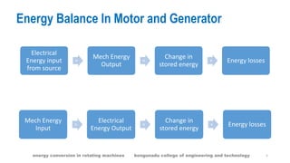
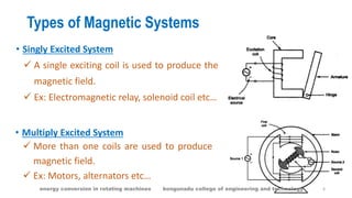
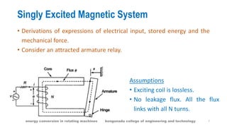
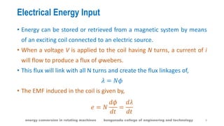
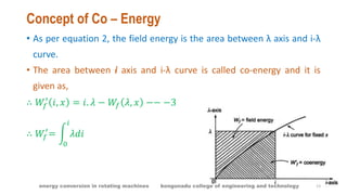
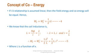
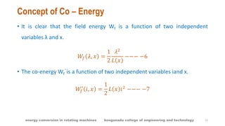
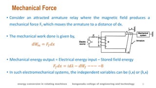
ELECTROMECHANICAL ENERGY CONVERSION AND CONCEPTS IN
ROTATING MACHINES
Content:
 Introduction to Electromechanical Energy Conversion .
 Energy balance equation.
 Singly excited system
 Concept of co-energy
 Magnetic Field Energy Stored
 References
energy conversion in rotating machines kongunadu college of engineering and technology 1
Introduction to ElectroMechanical Energy Conversion
• Electrical energy can be transmitted to long distances with ease and it
is highly efficient.
• It acts as a transmitting link for transporting other forms of energy.
• Devices for EMEC are,
 Transducers which are used for low energy conversion.
 Relays, solenoids and actuators which produce mechanical force
or torque.
 Motors and generators which are used for continuous energy
conversion.
2energy conversion in rotating machines kongunadu college of engineering and technology
ElectroMechanical Energy Conversion
• EMEC takes place via magnetic field because of its higher energy
storing capacity.
• The fields involved with such electromechanical devices must be
slowly varying due to inertia in the mechanical parts.
• Such fields are called quasi static fields.
3energy conversion in rotating machines kongunadu college of engineering and technology
Energy Balance
• Principle of conservation of energy – Energy can neither be created
nor destroyed. But it can be transformed from one form to other.
• Not the entire energy be transformed to other form.
• There are some energy loss.
• Some part of the energy is stored in the form of magnetic field.
• Thus the input energy has three parts.
 Transformed energy
 Energy loss
 Stored energy
4energy conversion in rotating machines kongunadu college of engineering and technology
Energy Balance In Motor and Generator
Electrical
Energy input
from source
=
Mech Energy
Output
+
Change in
stored energy
+ Energy losses
Mech Energy
Input
=
Electrical
Energy Output
+
Change in
stored energy
+ Energy losses
5energy conversion in rotating machines kongunadu college of engineering and technology
Types of Magnetic Systems
• Singly Excited System
 A single exciting coil is used to produce the
magnetic field.
 Ex: Electromagnetic relay, solenoid coil etc…
• Multiply Excited System
 More than one coils are used to produce
magnetic field.
 Ex: Motors, alternators etc…
6energy conversion in rotating machines kongunadu college of engineering and technology
Singly Excited Magnetic System
• Derivations of expressions of electrical input, stored energy and the
mechanical force.
• Consider an attracted armature relay.
Assumptions
• Exciting coil is lossless.
• No leakage flux. All the flux
links with all N turns.
7energy conversion in rotating machines kongunadu college of engineering and technology
Electrical Energy Input
• Energy can be stored or retrieved from a magnetic system by means
of an exciting coil connected to an electric source.
• When a voltage V is applied to the coil having N turns, a current of i
will flow to produce a flux of φwebers.
• This flux will link with all N turns and create the flux linkages of,
𝜆 = 𝑁𝜙
• The EMF induced in the coil is given by,
𝑒 = 𝑁
𝑑𝜙
𝑑𝑡
=
𝑑𝜆
𝑑𝑡
8energy conversion in rotating machines kongunadu college of engineering and technology
Electrical Energy Input
• Applying KVL to the coil circuit,
𝑉 − 𝑖. 𝑅 − 𝑒 = 0
𝑉 = 𝑖. 𝑅 + 𝑒
𝑉 = 𝑖. 𝑅 +
𝑑𝜆
𝑑𝑡
• The energy input to the coil due to the flow of current i in time dt is,
𝑑𝑊𝑒 = 𝑒. 𝑖 𝑑𝑡
𝑑𝑊𝑒 =
𝑑𝜆
𝑑𝑡
. 𝑖 𝑑𝑡 = 𝑖. 𝑑𝜆 = 𝑖. 𝑑 𝑁. 𝜙 = 𝑁. 𝑖. 𝑑𝜙 = ℱ. 𝑑𝜙 −−− −1
9energy conversion in rotating machines kongunadu college of engineering and technology
Magnetic Field Energy Stored
• Consider that the armature is fixed at position x. Hence mechanical
work done is zero.
• Hence the entire electrical energy input gets stored in the magnetic
field.
𝑑𝑊𝑓 = 𝑑𝑊𝑒 = 𝑖. 𝑑𝜆 = ℱ. 𝑑𝜙
• The energy stored when there is a change in flux or flux linkages can
be written as,
𝑊𝑓 = 𝑖 𝜆 𝑑𝜆 =
𝜆
0
ℱ 𝜙 𝑑𝜙
𝜙
0
−−− −2
10energy conversion in rotating machines kongunadu college of engineering and technology
Magnetic Field Energy Stored
i – λ Relationship
• It is similar to the magnetization curve which varies with x.
• The air-gap between armature and core varies with x.
• Total reluctance of the magnetic path decreases with increase in x.
𝑖 = 𝑖 𝜆, 𝑥
𝜆 = 𝜆 𝑖, 𝑥
11energy conversion in rotating machines kongunadu college of engineering and technology
Magnetic Field Energy Stored
• Depending upon the independent variable, the stored field energy is
also a function of i, x or λ, x.
∴ 𝑊𝑓 = 𝑊𝑓 𝜆, 𝑥 𝑜𝑟 𝑊𝑓 = 𝑊𝑓 𝑖, 𝑥
• If x is changed, then energy interchange takes place between the
magnetic field and mechanical system.
• If x is constant, then energy interchange takes place between electric
system and magnetic field.
12energy conversion in rotating machines kongunadu college of engineering and technology
Concept of Co – Energy
• As per equation 2, the field energy is the area between λ axis and i-λ
curve.
• The area between i axis and i-λ curve is called co-energy and it is
given as,
∴ 𝑊𝑓
′
𝑖, 𝑥 = 𝑖. 𝜆 − 𝑊𝑓 𝜆, 𝑥 −− −3
∴ 𝑊𝑓
′
= 𝜆𝑑𝑖
𝑖
0
13energy conversion in rotating machines kongunadu college of engineering and technology
Concept of Co – Energy
• If i-λ relationship is assumed linear, then the field energy and co-energy will
be equal. Hence,
𝑊𝑓 = 𝑊𝑓
′
=
1
2
𝑖𝜆 −−− −4
• We know that the coil inductance is,
𝐿 =
𝑁𝜙
𝑖
=
𝜆
𝑖
; ∴ 𝜆 = 𝐿. 𝑖 𝑎𝑛𝑑 𝑖 =
𝜆
𝐿
∴ 𝑊𝑓 = 𝑊𝑓
′
=
1
2
𝜆2
𝐿
=
1
2
𝐿. 𝑖2 −−− −5
• Where L is a function of x.
energy conversion in rotating machines kongunadu college
of engineering and technology
14
Concept of Co – Energy
• It is clear that the field energy Wf is a function of two independent
variables λ and x.
𝑊𝑓 𝜆, 𝑥 =
1
2
𝜆2
𝐿 𝑥
−−− −6
• The co-energy Wf
’ is a function of two independent variables iand x.
𝑊𝑓
′
𝑖, 𝑥 =
1
2
𝐿 𝑥 𝑖2
−−− −7
15energy conversion in rotating machines kongunadu college of engineering and technology
Mechanical Force
• Consider an attracted armature relay where the magnetic field produces a
mechanical force Ff which moves the armature to a distance of dx.
• The mechanical work done is given by,
𝑑𝑊𝑚 = 𝐹𝑓 𝑑𝑥
• Mechanical energy output = Electrical energy input – Stored field energy
𝐹𝑓 𝑑𝑥 = 𝑖𝑑𝜆 − 𝑑𝑊𝑓 −−− −8
• In such electromechanical systems, the independent variables can be (i,x) or (λ,x)
16energy conversion in rotating machines kongunadu college of engineering and technology
Mechanical Force
Case 1: Independent variables are (i,x). i.e current constant
• Thus λ changes as i and x changes. Hence,
𝜆 = 𝜆 𝑖, 𝑥
𝑑𝜆 =
𝜕𝜆
𝜕𝑖
𝑑𝑖 +
𝜕𝜆
𝜕𝑥
𝑑𝑥 −−− −9
𝑊𝑓 = 𝑊𝑓 𝑖, 𝑥
𝑑𝑊𝑓 =
𝜕𝑊𝑓
𝜕𝑖
𝑑𝑖 +
𝜕𝑊𝑓
𝜕𝑥
𝑑𝑥 −−− −10
Substituting eqn 9 and eqn 10 in eqn 8, we get,
𝐹𝑓 𝑑𝑥 = 𝑖
𝜕𝜆
𝜕𝑖
𝑑𝑖 + 𝑖
𝜕𝜆
𝜕𝑥
𝑑𝑥 −
𝜕𝑊𝑓
𝜕𝑖
𝑑𝑖 −
𝜕𝑊𝑓
𝜕𝑥
𝑑𝑥
17energy conversion in rotating machines kongunadu college of engineering and technology
Mechanical Force
𝐹𝑓 𝑑𝑥 = 𝑖
𝜕𝜆
𝜕𝑥
−
𝜕𝑊𝑓
𝜕𝑥
𝑑𝑥 + 𝑖
𝜕𝜆
𝜕𝑖
−
𝜕𝑊𝑓
𝜕𝑖
𝑑𝑖
𝐹𝑓 𝑑𝑥 = 𝑖
𝜕𝜆
𝜕𝑥
−
𝜕𝑊𝑓
𝜕𝑥
𝑑𝑥
𝐹𝑓 = 𝑖
𝜕𝜆
𝜕𝑥
−
𝜕𝑊𝑓
𝜕𝑥
𝐹𝑓 =
𝜕
𝜕𝑥
𝑖𝜆 − 𝑊𝑓
𝐹𝑓 =
𝜕𝑊𝑓
′
𝑖, 𝑥
𝜕𝑥
18energy conversion in rotating machines kongunadu college of engineering and technology
Mechanical Force
Case 2: Independent variables are (λ,x). i.e voltage constant
• Thus i changes as λ and x changes. Hence,
𝑖 = 𝑖 𝜆, 𝑥
𝑊𝑓 = 𝑊𝑓 𝜆, 𝑥
𝑑𝑊𝑓 =
𝜕𝑊𝑓
𝜕𝜆
𝑑𝜆 +
𝜕𝑊𝑓
𝜕𝑥
𝑑𝑥 −−− −11
Substituting eqn 10 in eqn 8, we get,
𝐹𝑓 𝑑𝑥 = 𝑖𝑑𝜆 −
𝜕𝑊𝑓
𝜕𝜆
𝑑𝜆 −
𝜕𝑊𝑓
𝜕𝑥
𝑑𝑥
𝐹𝑓 𝑑𝑥 = −
𝜕𝑊𝑓
𝜕𝑥
𝑑𝑥 + 𝑖 −
𝜕𝑊𝑓
𝜕𝜆
𝑑𝜆
𝐹𝑓 = −
𝜕𝑊𝑓 𝜆, 𝑥
𝜕𝑥
19energy conversion in rotating machines kongunadu college of engineering and technology
• Using fourier analysis, the equation for mmf wave is given by,
ℱ 𝑎1 =
4
𝜋
𝑇𝑝ℎ × 𝑖 𝑎
𝑃
cos 𝜃
• Because of short pitched and distributed winding, the mmf gets reduced by
a factor Kp and Kd. Hence the equation for mmf wave is given by,
ℱ 𝑎1 =
4
𝜋
𝐾 𝑝 𝐾 𝑑
𝑇𝑝ℎ × 𝑖 𝑎
𝑃
cos 𝜃 = 𝐹1𝑝 cos 𝜃
20energy conversion in rotating machines kongunadu college of engineering and technology
21
Conclusion:
Electromechanical energy conversion steps , energy balance equation, singly excited
system and concept of co-energy is explained in detail with suitable diagrams.
References:
1.P. C. Sen., ‘Principles of Electrical Machines and Power Electronics’, John Wiley
& Sons,1997.
2.P.S. Bimbhra, ‘Electrical Machinery’, Khanna Publishers, 2003.
3.S.Sarma & K.Pathak “Electric Machines”, Cengage Learning India (P) Ltd.,
Delhi, 2011.
4.U.A.Bakshi&M.N.Bakshi “Electric Machines-I”, Technical publications,2015.
5.Other Web Sources.
energy conversion in rotating machines kongunadu college of engineering and technology

Concept in rotating machines

  • 1.
    ELECTROMECHANICAL ENERGY CONVERSIONAND CONCEPTS IN ROTATING MACHINES Content:  Introduction to Electromechanical Energy Conversion .  Energy balance equation.  Singly excited system  Concept of co-energy  Magnetic Field Energy Stored  References energy conversion in rotating machines kongunadu college of engineering and technology 1
  • 2.
    Introduction to ElectroMechanicalEnergy Conversion • Electrical energy can be transmitted to long distances with ease and it is highly efficient. • It acts as a transmitting link for transporting other forms of energy. • Devices for EMEC are,  Transducers which are used for low energy conversion.  Relays, solenoids and actuators which produce mechanical force or torque.  Motors and generators which are used for continuous energy conversion. 2energy conversion in rotating machines kongunadu college of engineering and technology
  • 3.
    ElectroMechanical Energy Conversion •EMEC takes place via magnetic field because of its higher energy storing capacity. • The fields involved with such electromechanical devices must be slowly varying due to inertia in the mechanical parts. • Such fields are called quasi static fields. 3energy conversion in rotating machines kongunadu college of engineering and technology
  • 4.
    Energy Balance • Principleof conservation of energy – Energy can neither be created nor destroyed. But it can be transformed from one form to other. • Not the entire energy be transformed to other form. • There are some energy loss. • Some part of the energy is stored in the form of magnetic field. • Thus the input energy has three parts.  Transformed energy  Energy loss  Stored energy 4energy conversion in rotating machines kongunadu college of engineering and technology
  • 5.
    Energy Balance InMotor and Generator Electrical Energy input from source = Mech Energy Output + Change in stored energy + Energy losses Mech Energy Input = Electrical Energy Output + Change in stored energy + Energy losses 5energy conversion in rotating machines kongunadu college of engineering and technology
  • 6.
    Types of MagneticSystems • Singly Excited System  A single exciting coil is used to produce the magnetic field.  Ex: Electromagnetic relay, solenoid coil etc… • Multiply Excited System  More than one coils are used to produce magnetic field.  Ex: Motors, alternators etc… 6energy conversion in rotating machines kongunadu college of engineering and technology
  • 7.
    Singly Excited MagneticSystem • Derivations of expressions of electrical input, stored energy and the mechanical force. • Consider an attracted armature relay. Assumptions • Exciting coil is lossless. • No leakage flux. All the flux links with all N turns. 7energy conversion in rotating machines kongunadu college of engineering and technology
  • 8.
    Electrical Energy Input •Energy can be stored or retrieved from a magnetic system by means of an exciting coil connected to an electric source. • When a voltage V is applied to the coil having N turns, a current of i will flow to produce a flux of φwebers. • This flux will link with all N turns and create the flux linkages of, 𝜆 = 𝑁𝜙 • The EMF induced in the coil is given by, 𝑒 = 𝑁 𝑑𝜙 𝑑𝑡 = 𝑑𝜆 𝑑𝑡 8energy conversion in rotating machines kongunadu college of engineering and technology
  • 9.
    Electrical Energy Input •Applying KVL to the coil circuit, 𝑉 − 𝑖. 𝑅 − 𝑒 = 0 𝑉 = 𝑖. 𝑅 + 𝑒 𝑉 = 𝑖. 𝑅 + 𝑑𝜆 𝑑𝑡 • The energy input to the coil due to the flow of current i in time dt is, 𝑑𝑊𝑒 = 𝑒. 𝑖 𝑑𝑡 𝑑𝑊𝑒 = 𝑑𝜆 𝑑𝑡 . 𝑖 𝑑𝑡 = 𝑖. 𝑑𝜆 = 𝑖. 𝑑 𝑁. 𝜙 = 𝑁. 𝑖. 𝑑𝜙 = ℱ. 𝑑𝜙 −−− −1 9energy conversion in rotating machines kongunadu college of engineering and technology
  • 10.
    Magnetic Field EnergyStored • Consider that the armature is fixed at position x. Hence mechanical work done is zero. • Hence the entire electrical energy input gets stored in the magnetic field. 𝑑𝑊𝑓 = 𝑑𝑊𝑒 = 𝑖. 𝑑𝜆 = ℱ. 𝑑𝜙 • The energy stored when there is a change in flux or flux linkages can be written as, 𝑊𝑓 = 𝑖 𝜆 𝑑𝜆 = 𝜆 0 ℱ 𝜙 𝑑𝜙 𝜙 0 −−− −2 10energy conversion in rotating machines kongunadu college of engineering and technology
  • 11.
    Magnetic Field EnergyStored i – λ Relationship • It is similar to the magnetization curve which varies with x. • The air-gap between armature and core varies with x. • Total reluctance of the magnetic path decreases with increase in x. 𝑖 = 𝑖 𝜆, 𝑥 𝜆 = 𝜆 𝑖, 𝑥 11energy conversion in rotating machines kongunadu college of engineering and technology
  • 12.
    Magnetic Field EnergyStored • Depending upon the independent variable, the stored field energy is also a function of i, x or λ, x. ∴ 𝑊𝑓 = 𝑊𝑓 𝜆, 𝑥 𝑜𝑟 𝑊𝑓 = 𝑊𝑓 𝑖, 𝑥 • If x is changed, then energy interchange takes place between the magnetic field and mechanical system. • If x is constant, then energy interchange takes place between electric system and magnetic field. 12energy conversion in rotating machines kongunadu college of engineering and technology
  • 13.
    Concept of Co– Energy • As per equation 2, the field energy is the area between λ axis and i-λ curve. • The area between i axis and i-λ curve is called co-energy and it is given as, ∴ 𝑊𝑓 ′ 𝑖, 𝑥 = 𝑖. 𝜆 − 𝑊𝑓 𝜆, 𝑥 −− −3 ∴ 𝑊𝑓 ′ = 𝜆𝑑𝑖 𝑖 0 13energy conversion in rotating machines kongunadu college of engineering and technology
  • 14.
    Concept of Co– Energy • If i-λ relationship is assumed linear, then the field energy and co-energy will be equal. Hence, 𝑊𝑓 = 𝑊𝑓 ′ = 1 2 𝑖𝜆 −−− −4 • We know that the coil inductance is, 𝐿 = 𝑁𝜙 𝑖 = 𝜆 𝑖 ; ∴ 𝜆 = 𝐿. 𝑖 𝑎𝑛𝑑 𝑖 = 𝜆 𝐿 ∴ 𝑊𝑓 = 𝑊𝑓 ′ = 1 2 𝜆2 𝐿 = 1 2 𝐿. 𝑖2 −−− −5 • Where L is a function of x. energy conversion in rotating machines kongunadu college of engineering and technology 14
  • 15.
    Concept of Co– Energy • It is clear that the field energy Wf is a function of two independent variables λ and x. 𝑊𝑓 𝜆, 𝑥 = 1 2 𝜆2 𝐿 𝑥 −−− −6 • The co-energy Wf ’ is a function of two independent variables iand x. 𝑊𝑓 ′ 𝑖, 𝑥 = 1 2 𝐿 𝑥 𝑖2 −−− −7 15energy conversion in rotating machines kongunadu college of engineering and technology
  • 16.
    Mechanical Force • Consideran attracted armature relay where the magnetic field produces a mechanical force Ff which moves the armature to a distance of dx. • The mechanical work done is given by, 𝑑𝑊𝑚 = 𝐹𝑓 𝑑𝑥 • Mechanical energy output = Electrical energy input – Stored field energy 𝐹𝑓 𝑑𝑥 = 𝑖𝑑𝜆 − 𝑑𝑊𝑓 −−− −8 • In such electromechanical systems, the independent variables can be (i,x) or (λ,x) 16energy conversion in rotating machines kongunadu college of engineering and technology
  • 17.
    Mechanical Force Case 1:Independent variables are (i,x). i.e current constant • Thus λ changes as i and x changes. Hence, 𝜆 = 𝜆 𝑖, 𝑥 𝑑𝜆 = 𝜕𝜆 𝜕𝑖 𝑑𝑖 + 𝜕𝜆 𝜕𝑥 𝑑𝑥 −−− −9 𝑊𝑓 = 𝑊𝑓 𝑖, 𝑥 𝑑𝑊𝑓 = 𝜕𝑊𝑓 𝜕𝑖 𝑑𝑖 + 𝜕𝑊𝑓 𝜕𝑥 𝑑𝑥 −−− −10 Substituting eqn 9 and eqn 10 in eqn 8, we get, 𝐹𝑓 𝑑𝑥 = 𝑖 𝜕𝜆 𝜕𝑖 𝑑𝑖 + 𝑖 𝜕𝜆 𝜕𝑥 𝑑𝑥 − 𝜕𝑊𝑓 𝜕𝑖 𝑑𝑖 − 𝜕𝑊𝑓 𝜕𝑥 𝑑𝑥 17energy conversion in rotating machines kongunadu college of engineering and technology
  • 18.
    Mechanical Force 𝐹𝑓 𝑑𝑥= 𝑖 𝜕𝜆 𝜕𝑥 − 𝜕𝑊𝑓 𝜕𝑥 𝑑𝑥 + 𝑖 𝜕𝜆 𝜕𝑖 − 𝜕𝑊𝑓 𝜕𝑖 𝑑𝑖 𝐹𝑓 𝑑𝑥 = 𝑖 𝜕𝜆 𝜕𝑥 − 𝜕𝑊𝑓 𝜕𝑥 𝑑𝑥 𝐹𝑓 = 𝑖 𝜕𝜆 𝜕𝑥 − 𝜕𝑊𝑓 𝜕𝑥 𝐹𝑓 = 𝜕 𝜕𝑥 𝑖𝜆 − 𝑊𝑓 𝐹𝑓 = 𝜕𝑊𝑓 ′ 𝑖, 𝑥 𝜕𝑥 18energy conversion in rotating machines kongunadu college of engineering and technology
  • 19.
    Mechanical Force Case 2:Independent variables are (λ,x). i.e voltage constant • Thus i changes as λ and x changes. Hence, 𝑖 = 𝑖 𝜆, 𝑥 𝑊𝑓 = 𝑊𝑓 𝜆, 𝑥 𝑑𝑊𝑓 = 𝜕𝑊𝑓 𝜕𝜆 𝑑𝜆 + 𝜕𝑊𝑓 𝜕𝑥 𝑑𝑥 −−− −11 Substituting eqn 10 in eqn 8, we get, 𝐹𝑓 𝑑𝑥 = 𝑖𝑑𝜆 − 𝜕𝑊𝑓 𝜕𝜆 𝑑𝜆 − 𝜕𝑊𝑓 𝜕𝑥 𝑑𝑥 𝐹𝑓 𝑑𝑥 = − 𝜕𝑊𝑓 𝜕𝑥 𝑑𝑥 + 𝑖 − 𝜕𝑊𝑓 𝜕𝜆 𝑑𝜆 𝐹𝑓 = − 𝜕𝑊𝑓 𝜆, 𝑥 𝜕𝑥 19energy conversion in rotating machines kongunadu college of engineering and technology
  • 20.
    • Using fourieranalysis, the equation for mmf wave is given by, ℱ 𝑎1 = 4 𝜋 𝑇𝑝ℎ × 𝑖 𝑎 𝑃 cos 𝜃 • Because of short pitched and distributed winding, the mmf gets reduced by a factor Kp and Kd. Hence the equation for mmf wave is given by, ℱ 𝑎1 = 4 𝜋 𝐾 𝑝 𝐾 𝑑 𝑇𝑝ℎ × 𝑖 𝑎 𝑃 cos 𝜃 = 𝐹1𝑝 cos 𝜃 20energy conversion in rotating machines kongunadu college of engineering and technology
  • 21.
    21 Conclusion: Electromechanical energy conversionsteps , energy balance equation, singly excited system and concept of co-energy is explained in detail with suitable diagrams. References: 1.P. C. Sen., ‘Principles of Electrical Machines and Power Electronics’, John Wiley & Sons,1997. 2.P.S. Bimbhra, ‘Electrical Machinery’, Khanna Publishers, 2003. 3.S.Sarma & K.Pathak “Electric Machines”, Cengage Learning India (P) Ltd., Delhi, 2011. 4.U.A.Bakshi&M.N.Bakshi “Electric Machines-I”, Technical publications,2015. 5.Other Web Sources. energy conversion in rotating machines kongunadu college of engineering and technology