
Recommended
More Related Content
What's hot
What's hot (20)
Similar to Ppt 2
Similar to Ppt 2 (20)
More from ragulkncet
Recently uploaded
Recently uploaded (20)
Ppt 2
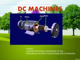
- 1. S.RAGUL, ASSISTANT PROFESSOR, DEPARTMENT OF EEE, KONGUNADU COLLEGE OF ENGINEERING AND TECHNOLOGY DC MACHINES 1
- 2. 2 Content: Introduction to LAW and rules Working principle , construction and important parts. References
- 3. Fleming’s left hand rule 3
- 4. Fleming’s left hand rule Used to determine the direction of force acting on a current carrying conductor placed in a magnetic field . The middle finger , the fore finger and thumb of the left hand are kept at right angles to one another . The middle finger represent the direction of current The fore finger represent the direction of magnetic field The thumb will indicate the direction of force acting on the conductor . This rule is used in motors.4
- 5. Fleming’s Right hand rule 5
- 6. Fleming’s Right hand rule Used to determine the direction of emf induced in a conductor The middle finger , the fore finger and thumb of the left hand are kept at right angles to one another. The fore finger represent the direction of magnetic field The thumb represent the direction of motion of the conductor The middle finger will indicate the direction of the inducted emf . This rule is used in DC Generators6
- 7. Len’s Law The direction of induced emf is given by Lenz’s law . According to this law, the induced emf will be acting in such a way so as to oppose the very cause of production of it . e = -N (dØ/dt) volts 7
- 8. DC Generator Mechanical energy is converted to electric energy Three requirements are essential 1. Conductors 2. Magnetic field 3. Mechanical energy 8
- 9. Working principle A generator works on the principles of Faraday’s law of electromagnetic induction Whenever a conductor is moved in the magnetic field , an emf is induced and the magnitude of the induced emf is directly proportional to the rate of change of flux linkage. This emf causes a current flow if the conductor circuit is closed . 9
- 11. Sectional view of a DC machine 11
- 12. Construction of DC Generator Field system Armature core Armature winding Commutator Brushes 12
- 13. Field winding 13
- 14. Rotor and rotor winding 14
- 15. Working principle of DC motor 15
- 16. Working principle of DC motor 16
- 17. Force in DC motor 17
- 18. Armature winding There are 2 types of winding Lap and Wave winding Lap winding A = P The armature windings are divided into no. of sections equal to the no of poles Wave winding A = 2 It is used in low current output and high voltage. 2 brushes 18
- 19. Field system It is for uniform magnetic field within which the armature rotates. Electromagnets are preferred in comparison with permanent magnets They are cheap , smaller in size , produce greater magnetic effect and Field strength can be varied 19
- 20. Field system consists of the following parts Yoke Pole cores Pole shoes Field coils 20
- 21. Armature core The armature core is cylindrical High permeability silicon steel stampings Impregnated Lamination is to reduce the eddy current loss 21
- 22. Commutator Connect with external circuit Converts ac into unidirectional current Cylindrical in shape Made of wedge shaped copper segments Segments are insulated from each other Each commutator segment is connected to armature conductors by means of a cu strip called riser. No of segments equal to no of coils 22
- 23. Carbon brush Carbon brushes are used in DC machines because they are soft materials It does not generate spikes when they contact commutator To deliver the current thro armature Carbon is used for brushes because it has negative temperature coefficient of resistance Self lubricating , takes its shape , improving area of contact 23
- 24. Brush rock and holder 24
- 25. Carbon brush Brush leads (pig tails) Brush rocker ( brush gear ) Front end cover Rear end cover Cooling fan Bearing Terminal box 25
- 26. 26 Conclusion: The DC machines working principle, construction and different parts of machine is explained in detail with suitable diagrams. References: • 1.P. C. Sen., ‘Principles of Electrical Machines and Power Electronics’, John Wiley & Sons, 1997. • 2.Deshpande M. V., “Electrical Machines” PHI Learning Pvt. Ltd., New Delhi, 2011. • 3.P.S. Bimbhra, ‘Electrical Machinery’, Khanna Publishers, 2003. • 4.S.Sarma & K.Pathak “Electric Machines”, Cengage Learning India (P) Ltd., Delhi, 2011. • 5.U.A.Bakshi&M.N.Bakshi “Electric Machines-I”,Technical publications, 2015. • 6.Other Web Sources