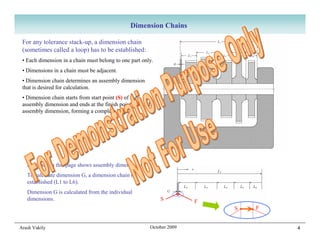
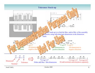
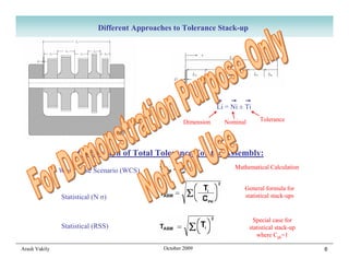
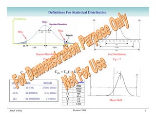
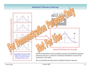
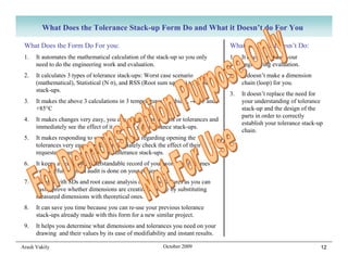
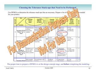
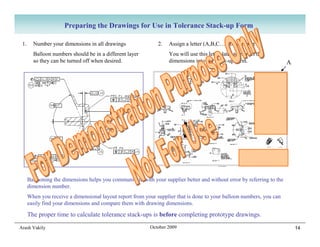
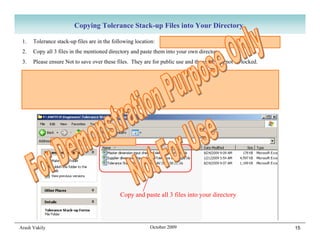
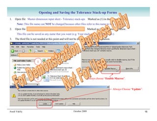
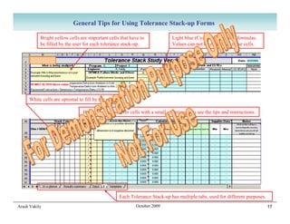
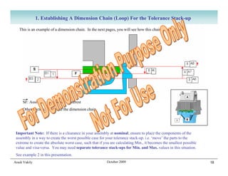
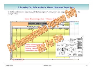
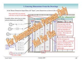
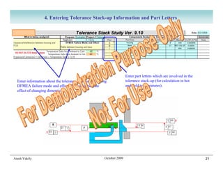
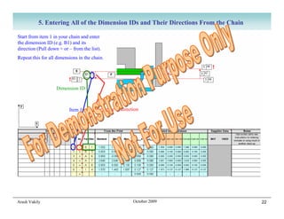
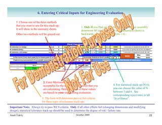
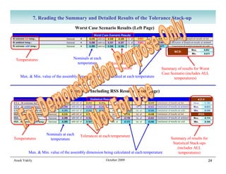
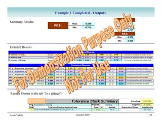
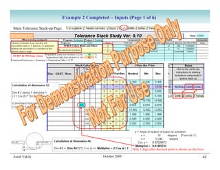
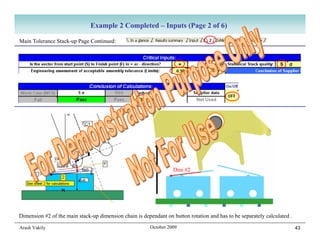
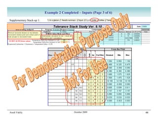
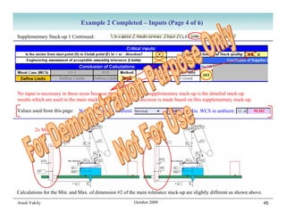
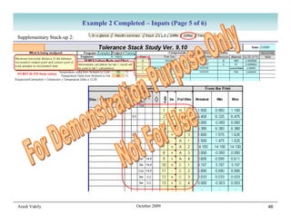
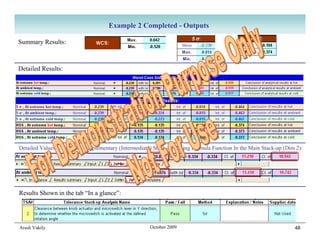
Performing Tolerance
     Stack-ups Using
  Automated Excel Form

Arash Vakily   October 2009   1
Why do we Have to Perform Tolerance Stack-ups
You will know which dimensions to show on your drawings:
Only dimensions that are used in a tolerance stack-up are necessary to be shown on the drawing; plus a few extra dimensions
for clarification, total part size, etc. Also, if the dimensions necessary for tolerance stack-ups are not on the drawing, it will
create problems for you later.

Your time during an 8D / Root Cause Analysis will not be consumed to prove your design’s fit & function:
During DV and PV, no failures related to interference, clearance, or travel should occur if your stack-ups are correct. If there
are failures, it is easy to prove they are not related to design when the tolerance stack-up is ready.

No need for repetitive tool changes between DV and production (no trial and error):
When the product works first time all the time, no dimension related tool changes are necessary. Tool changes are expensive
and time consuming.

Your product will work without a glitch during the entire life of the program:
No need for very costly tool changes after production started, or calls from customer for expensive warranty claims.

Audits are not an issue:
To keep our company’s TS16949 certification, auditors come to check our design procedure on an annual basis. To be ready
for audits, we have to have our documents in order, including tolerance stack-ups.

It is easy to answer requests from suppliers regarding tolerances and dimensions of their tools:
When the suppliers ask if they can open a tolerance or change a nominal dimension, all you need to do is to put their
requested dimension or tolerance into your already prepared stack-up.

Arash Vakily                                                October 2009                                                        2
Introduction to Tolerance Stack-up
             Concepts and Formulas


Arash Vakily          October 2009          3
Dimension Chains

 For any tolerance stack-up, a dimension chain
 (sometimes called a loop) has to be established:
 • Each dimension in a chain must belong to one part only.
 • Dimensions in a chain must be adjacent.
 • Dimension chain determines an assembly dimension
 that is desired for calculation.
 • Dimension chain starts from start point (S) of the
 assembly dimension and ends at the finish point (F) of the
 assembly dimension, forming a complete loop.


   Example on this page shows assembly dimension G.
   To calculate dimension G, a dimension chain is
   established (L1 to L6).
   Dimension G is calculated from the individual
   dimensions.                                                S         F
                                                                            S   F


Arash Vakily                                             October 2009               4
Tolerance Stack-up


                                                                           G = L1+L2+… = Σ Li

                                                       Tolerance stack-up is to find the Max. and/or Min. of the assembly
                                                       dimension, using individual part dimensions in the dimension
                                                       chain.


           G Max = L1 Max +L2       Min   +…                             G Min = L1 Min +L2      Max   +…
         All dimensions in        All dimensions in                     All dimensions in      All dimensions in
         positive direction       negative direction                    positive direction     negative direction


               Li = Ni ± Ti                    G = L1+L2+… = (N1+T1) + (N2+T2) + … = (N1+N2+…) + (T1+T2+…)
Dimension
                      Tolerance           Either add Max / Min dimensions          Or add nominals and tolerances separately
        Nominal

Arash Vakily                                             October 2009                                                       5
Different Approaches to Tolerance Stack-up


                                                                  Li = Ni ± Ti

                                                      Dimension     Nominal       Tolerance


                     Calculation of Total Tolerance For the Assembly:
                                                                        Mathematical Calculation
               Worst Case Scenario (WCS)

                                                                           General formula for
               Statistical (N σ)                                           statistical stack-ups


                                                                                Special case for
               Statistical (RSS)                                              statistical stack-up
                                                                                 where Cpk=1

Arash Vakily                                  October 2009                                           6
Definitions For Statistical Distribution
    Probability


        Min.                            Max.


                                                  Dim. value

                      Normal Distribution                                  6 σ Distribution
                            Cp = 1                                             Cp = 2


                  UL − LL            C pk = C p (1 − k )
          Cp =
                    6σ


                                                                            Mean Shift


Arash Vakily                                        October 2009                              7
Statistical Tolerance Stack-up
       Statistical Distribution For Each Dimension in the Chain


                                                                                                                            Statistical Distribution For Assembly

                                                                  Assembly Processes That        Statistical distribution of the assembly dimension calculated by statistical
                                                                   Affect Fit and Function       tolerance stack-up is a function of statistical distribution of each of the
                                                                    (Using Fixtures, etc.)       dimensions in the chain.
                                                                                                 We can calculate the reject rate by statistical tolerance stack-up.

Arash Vakily                                                                                               October 2009                                                         8
Quick Review of Other Approaches to Statistical Tolerance Stack-ups

               Bender Factor (RSS x 1.5)                        Arithmetic (worst case) stack of mean shifts
                                                                 + RSS stack of distributions with inflation
                                                                  factors for each dimension’s distribution


                                                                      Various Inflation Factors (c1,c2,…)

 Since these alternative approaches are based on
 assumptions in lieu of data, or need actual data to
 be useful, we do not explore them further for our
 theoretical tolerance stack-up.
 Once we have enough data of actual parts, we
 can perform a stack-up using the measured
 dimensional data and general statistical tolerance
 stack-up formulas for confirmation (if necessary).


Arash Vakily                                           October 2009                                            9
Accounting for GD&T in Dimension Chains
       Straight Dimensions                                          GD&Ts Referenced to Datum(s)


                                                                                        Envelope

                             Envelope                                    0.2         0.2
                                                     Always half-half (unless specifically specified otherwise)
                                                          Direction does not matter for tolerance stack-ups
           0.1             0.2                            (Nominal value equivalent is zero for all GD&T)

         GD&Ts With No Datum Reference – Present Special Case For Tolerance Stack-ups


                            Envelope


               0.1 total

                                                          All of the GD&T tolerance falls on one side
                                                         Direction is important for tolerance stack-ups
Arash Vakily                                        October 2009                                                  10
Performing Tolerance Stack-ups
            Using Automated Excel Form


Arash Vakily            October 2009        11
What Does the Tolerance Stack-up Form Do and What it Doesn’t do For You

 What Does the Form Do For you:                                                    What the Form Doesn’t Do:
 1.   It automates the mathematical calculation of the stack-up so you only        1.   It doesn’t replace your
      need to do the engineering work and evaluation.                                   engineering evaluation.
 2.   It calculates 3 types of tolerance stack-ups: Worst case scenario            2.   It doesn’t make a dimension
      (mathematical), Statistical (N σ), and RSS (Root sum square) tolerance            chain (loop) for you.
      stack-ups.
                                                                                   3.   It doesn’t replace the need for
 3.   It makes the above 3 calculations in 3 temperatures: Ambient, -40°C and           your understanding of tolerance
      +85°C                                                                             stack-up and the design of the
                                                                                        parts in order to correctly
 4.   It makes changes very easy, you can change dimensions or tolerances and
                                                                                        establish your tolerance stack-up
      immediately see the effect of it on all of your tolerance stack-ups.
                                                                                        chain.
 5.   It makes responding to supplier’s requests regarding opening the
      tolerances very easy, you can immediately check the effect of their
      requested change on all of your tolerance stack-ups.
 6.   It keeps a verifiable, understandable record of your work that becomes
      very useful when an audit is done on your project.
 7.   It helps with 8Ds and root cause analysis of the test failures as you can
      easily prove whether dimensions are creating an issue by substituting
      measured dimensions with theoretical ones.
 8.   It can save you time because you can re-use your previous tolerance
      stack-ups already made with this form for a new similar project.
 9.   It helps you determine what dimensions and tolerances you need on your
      drawing and their values by its ease of modifiability and instant results.

Arash Vakily                                               October 2009                                                 12
Choosing the Tolerance Stack-ups that Need to be Performed

   Use DFMEA to determine the tolerance stack-ups that are necessary. Prepare a list of tolerance stack-ups needed
   for your product.


  The proper time to prepare a DFMEA is at the design concept stage, and before completing the modeling.

Arash Vakily                                            October 2009                                                 13
Preparing the Drawings for Use in Tolerance Stack-up Form

 1.     Number your dimensions in all drawings                2.   Assign a letter (A,B,C…) to each part
        Balloon numbers should be in a different layer             You will use this letter later to extract the
        so they can be turned off when desired.                    dimensions into the stack-up form.                   A


      Ballooning the dimensions helps you communicate with your supplier better and without error by referring to the
      dimension number.
      When you receive a dimensional layout report from your supplier that is done to your balloon numbers, you can
      easily find your dimensions and compare them with drawing dimensions.

      The proper time to calculate tolerance stack-ups is before completing prototype drawings.
Arash Vakily                                               October 2009                                                     14
Copying Tolerance Stack-up Files into Your Directory

 1.   Tolerance stack-up files are in the following location:   F:SWITCHEngineersTolerance Stack-up Forms
 2.   Copy all 3 files in the mentioned directory and paste them into your own directory.
 3.   Please ensure Not to save over these files. They are for public use and therefore can not be locked.

 Very Important Note: After you start using your tolerance stack-up files, moving the files can create issues
 with file dependencies and give you incorrect results. Try not to move them at all.
 The only way to move the files is to have ALL of your stack-up files open and use “Save As” while all of them
 are open. CAD users (UG and CATIA) will appreciate that the same issue exists with moving CAD files.


                                             Copy and paste all 3 files into your directory


Arash Vakily                                              October 2009                                           15
Opening and Saving the Tolerance Stack-up Forms
1.   Open file Master dimension input sheet - Tolerance stack-ups Marked as (1) in the picture below.
      Note: This file name can NOT be changed because other files refer to this name to link to this file.
2.   Open file Tolerance Stack Study Form Vx-x AV xxxx xx xx               Marked as (2) in the picture below.
      This file can be saved as any name that you want (e.g. Your stack-up name or number.)
3.   The third file is not needed at this point and will not be discussed in this presentation.


                                Your Directory

                         1


                         2                                              Always choose “Enable Macros”.


                                                                                                  Always Choose “Update”.


Arash Vakily                                                October 2009                                                    16
General Tips for Using Tolerance Stack-up Forms

           Bright yellow cells are important cells that have to               Light blue (Cyan) cells contain formulas.
           be filled by the user for each tolerance stack-up.                 Values can not be entered in these cells.


     White cells are optional to fill by the user.

                                Hold your mouse over cells with a small red triangle to see the tips and instructions.


                                                     Each Tolerance Stack-up has multiple tabs, used for different purposes.
Arash Vakily                                                 October 2009                                                      17
1. Establishing A Dimension Chain (Loop) For the Tolerance Stack-up

   This is an example of a dimension chain. In the next pages, you will see how this chain is established.


     SF: Assembly dimension of Interest
     Other vectors: Comprise the dimension chain


 Important Note: If there is a clearance in your assembly at nominal, ensure to place the components of the
 assembly in a way to create the worst possible case for your tolerance stack-up. i.e. ‘move’ the parts to the
 extreme to create the absolute worst case, such that if you are calculating Min., it becomes the smallest possible
 value and visa-versa. You may need separate tolerance stack-ups for Min. and Max. values in this situation.
 See example 2 in this presentation.
Arash Vakily                                              October 2009                                                18
2. Entering Part Information in Master Dimension Input Sheet

   In the Master Dimension Input Sheet, tab “Part descriptions”, enter project data and part data as shown in the
   example below.


                            Master dimension input sheet - Tolerance stack-ups.xls


                             Fill the information for the
                             parts needed for your first
                             stack-up. More information
                             can be added later.


Arash Vakily                                             October 2009                                               19
3. Entering Dimensions From the Drawings

   In the Master Dimension Input Sheet, tab “Input”, enter dimensions as shown in the example below.

        Part names that you entered
        will show on top of each table

Examples below show how to enter
various dimensions and GD&T.


            1                                                                         You can enter only the
                                                                                      dimensions that are used
                                                                                      in your current tolerance
        3                                                                             stack-up regardless of
                                                                                      their order or dimension
                                                                                      number. More data can
    6                                                                                 be added later.


    9                                                                                 All the tolerances in
                                                                                      column –tol are considered
                                                                                      negative (multiplied by -1).
            12                                                                        Therefore, in most cases
GD&T not
                                                                                      there is no need to input a
referenced to a
                                                                                      minus sign.
datum


            19
              All other GD&T

Arash Vakily                                           October 2009                                                  20
4. Entering Tolerance Stack-up Information and Part Letters


                                                                       Enter part letters which are involved in the
  Enter information about the tolerance stack-up including             tolerance stack-up (for calculation in hot
  DFMEA failure mode and effect (To see immediate                      and cold temperatures).
  effect of changing dimensions).


Arash Vakily                                            October 2009                                                  21
5. Entering All of the Dimension IDs and Their Directions From the Chain

Start from item 1 in your chain and enter
the dimension ID (e.g. B1) and its
direction (Pull down + or – from the list).
Repeat this for all dimensions in the chain.


                    Dimension ID


                          Item 1        Negative Y direction


Arash Vakily                                             October 2009                 22
6. Entering Critical Inputs for Engineering Evaluation

     5. Choose one of the three methods
     that you want to use for this stack-up.
                                                               1. Only if you find out that the direction of your assembly
     It will show in the summary sheets.
                                                               dimension SF (and as a result your dimension chain) is
     Other two methods will be grayed out.                     backwards, change this sign from + to -


                             2. Enter Minimum and Maximum values
                             acceptable for the assembly dimension that you                4. For statistical stack-up (N σ),
                             are calculating. Determination of these values                you can choose the value of N
                             are based on your engineering evaluation.                     between 3 and 6. See
                                                                                           corresponding reject rates in tab
                            3. The form will determine pass or fail criteria               “In a Glance”.
                            for three types of tolerance stack-ups
Important Note: Always try to pass WCS criteria. Only if all other efforts fail (changing dimensions and modifying
design), statistical tolerance stack-up should be used to determine the degree of risk / failure rate.
Arash Vakily                                              October 2009                                                       23
7. Reading the Summary and Detailed Results of the Tolerance Stack-up
                                       Worst Case Scenario Results (Left Page)


 Temperatures                      Nominals at each
                                     temperature         Tolerances at each
                                                            temperature                 Summary of results for Worst
                                                                                        Case Scenario (includes ALL
    Max. & Min. value of the assembly dimension being calculated at each temperature           temperatures)


                                 Statistical Including RSS Results (Right Page)


                    Nominals at each     Tolerances at each temperature
Temperatures          temperature                                                            Summary of results for
                                                                                              Statistical Stack-ups
                                                                                                 (includes ALL
         Max. & Min. value of the assembly dimension being calculated at each temperature         temperatures)
Arash Vakily                                            October 2009                                                  24
8. Reviewing & Updating All Your Tolerance Stack-ups in a Glance


           All of the Tolerance Stack-up final results are shown in the tab “In a glance”

           You can review the impact of changing a dimension or tolerance
           immediately by having your stack-up and “Master dimension input
           sheet” open. If you change a dimension or tolerance in the Master
           dimension input sheet, the result of all stack-ups will automatically
           update in real time. Therefore, you can immediately determine which
           stack-up result changes to “fail” and find out its related failure mode.


Arash Vakily                                               October 2009                     25
9. Printing A Summary of All of the Tolerance Stack-ups


               Go to tab “Results Summary”. You can print all of the important values of the tolerance stack-ups
                         (up to 20 tolerance stack-ups in one file) including detailed results in one page


Arash Vakily                                             October 2009                                              26
10. Adding More Tolerance Stack-ups to a File


     First tab for stack-up is called “1”
     The first stack-up is done in sheet 1

          To add a new tolerance stack-up sheet, right click on tab “Template”
                                                                                      NOTE: Always leave the
          Choose “Move or Copy”                                                       tab “Template” empty and
          Check the box “Create a copy”                                               ready for making a copy
          Choose a location for your new tab (you can drag it to any location later
          Press “OK”
Arash Vakily                                              October 2009                                           27
11. Advanced Features of the Tolerance Stack-up Form in a Glance
                    Hold your mouse on the red triangles to see full instructions for each column


                                If the dimension in your drawing has a critical characteristic, you can enter
                                C in this column. This will ONLY affect statistical stack-up (N σ).

                              To project a dimension that is on an angle to the axis of tolerance stack-up,
                              use Sin, Cos, Tan, Cot and related angle in degrees in these columns

                   To multiply (or divide) a dimension, use this column. Best example of using this column is
                   when the dimension is a diameter and you need the radius. Use a multiplier of 0.5 and the
                   dimension and tolerances are multiplied by 0.5 (same as dividing by 2).


  To use a formula of your own, or to use the results of another tolerance stack-up, or even to use Min and Max
  results from two different stack-ups, enter F in the left column. Enter appropriate command in the right column
  (“Notes”).
  Note: In order to calculate the stack-up in Max./Min. temperatures, the form needs to know which part is used for
  the formula. Enter the part letter plus a zero (H0 in example above) to enable the form to calculate the temperature
  stack-ups.


                Hold your mouse over this cell to see full instructions and examples for using various types of formulas

Arash Vakily                                              October 2009                                                     28
12. More Advanced Features of the Tolerance Stack-up Form in a Glance
                     Hold your mouse on the red triangles to see full instructions for each column


   ONLY if you are certain that the distribution type for your
   dimension is not a Normal distribution, you can choose Uniform
   distribution. Exercise caution when using this feature. Also, it has
   to be used as a per-dimension basis only, not for all dimensions.
        If necessary, you can define specific values for Process capability (Cp) and Mean shift (k) which calculate a
        specific Cpk. Exercise extreme caution when using these columns and ensure Supplier Quality and Supplier are
        in agreement with you. ( Cpk = Cp . k )
        It should not become necessary to use these columns, as Omron Supplier Quality has specific rules which are
        embedded in the critical characteristic explained previously.
        Note: If a dimension is marked as a critical characteristic (See last page), the value for Cpk will be determined
        automatically. Therefore any values that you enter for Cp and k will not be considered. ( Cpk = Cp . k )


Arash Vakily                                               October 2009                                                     29
13. Turning Supplier Data On and Off
                                                   ON                                                  OFF


               Unless that you are entering supplier measured data, in order to avoid clutter, click
               on the button shown and choose “OFF” to hide all supplier data.


Arash Vakily                                          October 2009                                           30
14. Using Multiple Files for Larger Projects

Excel program and your computer have limitation on the amount of data that can be stored in a file. Also, the form is
designed for up to 20 tolerance stack-ups. If you exceed the memory or 20 tolerance stack-ups, use another Tolerance
Stack-up Study Form in the same directory for your tolerance stack-ups. Do not use another Master dimension input sheet.
ALL Tolerance Stack-up Study Forms (you can change their name) in one directory read their values from the same Master
input dimension sheet.

                                                             You can also open multiple files including Master
                                                             dimension input sheet, change a dimension or
 You can open multiple files including Master                tolerance value while monitoring all the tolerance
 dimension input sheet at the same time and work on          stack-up results to see if changing a dimension or
 them simultaneously to save time.                           tolerance has an adverse affect on any of the stack-ups.


Arash Vakily                                           October 2009                                                     31
Examples of Tolerance Stack-ups
          Preformed Using Excel Form


Arash Vakily           October 2009        32
Example 1: Interference Between Housing and Base For Rattle Prevention

                                                 In this example, we examine the interference (or clearance,
                                                 if exists) between housing and base of a switch. The PCB is
                                                 ‘sandwiched’ between the housing and the base. The base
                 Housing                         has flexible features that interfere with PCB (shown in red
                                                 in the picture across).


                                                     It is necessary to have an interference at all times to
                                                     prevent rattle between housing and base. This is the
                                                     DFMEA failure effect.

                  PCB


                                      Interference

                     Base
                                                       This tolerance stack-up is simple and straight-forward.
                                                       Its principle can be used for e-pads between housing and
                                                       base as well.


Arash Vakily                                 October 2009                                                         33
Established Dimension Chain (Loop) For Example 1


               A


    I          B


Y
                                                                                                5    A8
                            S                                            6   I4
                                 B1   1    F                                       4   A7

                   B3   2                                                                   3   A6


                                  X
Arash Vakily                                         October 2009                                    34
Example 1 Completed - Overview


Example 1 is explained and completed live during the presentation.

Arash Vakily                                            October 2009   35
Example 1 Completed - Inputs


Arash Vakily              October 2009        36
Example 1 Completed - Outputs

Summary Results:


Detailed Results:


Results Shown in the tab “In a glance”:


Arash Vakily                                October 2009         37
Example 2: Switch Cell Activation
  Button is always pushed fully                          Actual direction of the
  up by spring and follower.                               gap/interference               Button
                                                                                                             Housing Pins
                                                                                         Rotation


                                                        Y


                                                                                            Hole                            Slot
                                                       There is a clearance in X direction between PCB assembly hole and housing pin

                                                        In this example, we need to ensure that the micro-switch is activated at a
                                                        certain angle (in this case 14°).
                                                        For this purpose, we position the button at 14° and position the micro-switch
                                                        at its worst case (lowest point) of activation. Then we calculate the
          Micro switches shown in 3 positions           gap/interference between button actuator and micro-switch lever in Y
                                                        direction. This value must be zero or less (interference). If this value is
                                                        positive (gap), it means that the button actuator will not reach the micro-
                                                        switch lever.
                                                        Although the gap/interference is at an angle to Y axis, since we only need a
Micro switches are self-centering in the PCB holes      zero clearance or less (we are not interested in the value itself), we can project
                                                        the vector on Y axis to make the calculations less complicated.
Arash Vakily                                                           October 2009                                                          38
Example 2 Completed – Overview (Main Page)


Example 2 is explained and completed live during the presentation.

Arash Vakily                                            October 2009     39
Example 2 Completed – Overview (Supplementary Stack-up 1)


Supplementary Stack-up 1 calculates Min. value of dimension #2 of the main stack-up dimension chain in X direction .

Arash Vakily                                            October 2009                                                   40
Example 2 Completed – Overview (Supplementary Stack-up 2)


Supplementary Stack-up 2 calculates Max. value of dimension #2 of the main stack-up dimension chain in X direction .

Arash Vakily                                            October 2009                                                   41
Example 2 Completed – Inputs (Page 1 of 6)

Main Tolerance Stack-up Page:


               α

                                                             Only 1 digit after decimal point is shown on the form

Arash Vakily                                  October 2009                                                       42
Example 2 Completed – Inputs (Page 2 of 6)

Main Tolerance Stack-up Page Continued:


                                                                   Dim #2


Dimension #2 of the main stack-up dimension chain is dependant on button rotation and has to be separately calculated .

Arash Vakily                                             October 2009                                                     43
Example 2 Completed – Inputs (Page 3 of 6)

Supplementary Stack-up 1:


Arash Vakily                                  October 2009               44
Example 2 Completed – Inputs (Page 4 of 6)

Supplementary Stack-up 1 Continued:


No input is necessary in these areas because the only use of this supplementary stack-up is the detailed stack-up
results which are used in the main stack-up. No pass or fail decision is made based on this supplementary stack-up.

Values used from this page:   Nominal WCS in ambient:                               Min. WCS in ambient:


         2x Min                                                 2x Max


Calculations for the Min. and Max. of dimension #2 of the main tolerance stack-up are slightly different as shown above.

Arash Vakily                                             October 2009                                                      45
Example 2 Completed – Inputs (Page 5 of 6)

Supplementary Stack-up 2:


Arash Vakily                                  October 2009               46
Example 2 Completed – Inputs (Page 6 of 6)

Supplementary Stack-up 2 Continued:


No input is necessary in these areas because the only use of this supplementary stack-up is the detailed stack-up
results which are used in the main stack-up. No pass or fail decision is made based on this supplementary stack-up.

Values used from this page:   Nominal WCS in ambient:                               Min. WCS in ambient:


         2x Min                                                 2x Max


Calculations for the Min. and Max. of dimension #2 of the main tolerance stack-up are slightly different as shown above.

Arash Vakily                                             October 2009                                                      47
Example 2 Completed - Outputs

Summary Results:


Detailed Results:


Detailed Values Used From Supplementary (Intermediate) Stack-ups Using Formula Function In the Main Stack-up (Dim 2):


Results Shown in the tab “In a glance”:


Arash Vakily                                          October 2009                                               48
Thank You For Your
           Participation


Arash Vakily    October 2009   49

Performing Tolerance Stack Ups Using Automated Excel Calculator By Arash Vakily

  • 1.
    Performing Tolerance Stack-ups Using Automated Excel Form Arash Vakily October 2009 1
  • 2.
    Why do weHave to Perform Tolerance Stack-ups You will know which dimensions to show on your drawings: Only dimensions that are used in a tolerance stack-up are necessary to be shown on the drawing; plus a few extra dimensions for clarification, total part size, etc. Also, if the dimensions necessary for tolerance stack-ups are not on the drawing, it will create problems for you later. Your time during an 8D / Root Cause Analysis will not be consumed to prove your design’s fit & function: During DV and PV, no failures related to interference, clearance, or travel should occur if your stack-ups are correct. If there are failures, it is easy to prove they are not related to design when the tolerance stack-up is ready. No need for repetitive tool changes between DV and production (no trial and error): When the product works first time all the time, no dimension related tool changes are necessary. Tool changes are expensive and time consuming. Your product will work without a glitch during the entire life of the program: No need for very costly tool changes after production started, or calls from customer for expensive warranty claims. Audits are not an issue: To keep our company’s TS16949 certification, auditors come to check our design procedure on an annual basis. To be ready for audits, we have to have our documents in order, including tolerance stack-ups. It is easy to answer requests from suppliers regarding tolerances and dimensions of their tools: When the suppliers ask if they can open a tolerance or change a nominal dimension, all you need to do is to put their requested dimension or tolerance into your already prepared stack-up. Arash Vakily October 2009 2
  • 3.
    Introduction to ToleranceStack-up Concepts and Formulas Arash Vakily October 2009 3
  • 4.
    Dimension Chains Forany tolerance stack-up, a dimension chain (sometimes called a loop) has to be established: • Each dimension in a chain must belong to one part only. • Dimensions in a chain must be adjacent. • Dimension chain determines an assembly dimension that is desired for calculation. • Dimension chain starts from start point (S) of the assembly dimension and ends at the finish point (F) of the assembly dimension, forming a complete loop. Example on this page shows assembly dimension G. To calculate dimension G, a dimension chain is established (L1 to L6). Dimension G is calculated from the individual dimensions. S F S F Arash Vakily October 2009 4
  • 5.
    Tolerance Stack-up G = L1+L2+… = Σ Li Tolerance stack-up is to find the Max. and/or Min. of the assembly dimension, using individual part dimensions in the dimension chain. G Max = L1 Max +L2 Min +… G Min = L1 Min +L2 Max +… All dimensions in All dimensions in All dimensions in All dimensions in positive direction negative direction positive direction negative direction Li = Ni ± Ti G = L1+L2+… = (N1+T1) + (N2+T2) + … = (N1+N2+…) + (T1+T2+…) Dimension Tolerance Either add Max / Min dimensions Or add nominals and tolerances separately Nominal Arash Vakily October 2009 5
  • 6.
    Different Approaches toTolerance Stack-up Li = Ni ± Ti Dimension Nominal Tolerance Calculation of Total Tolerance For the Assembly: Mathematical Calculation Worst Case Scenario (WCS) General formula for Statistical (N σ) statistical stack-ups Special case for Statistical (RSS) statistical stack-up where Cpk=1 Arash Vakily October 2009 6
  • 7.
    Definitions For StatisticalDistribution Probability Min. Max. Dim. value Normal Distribution 6 σ Distribution Cp = 1 Cp = 2 UL − LL C pk = C p (1 − k ) Cp = 6σ Mean Shift Arash Vakily October 2009 7
  • 8.
    Statistical Tolerance Stack-up Statistical Distribution For Each Dimension in the Chain Statistical Distribution For Assembly Assembly Processes That Statistical distribution of the assembly dimension calculated by statistical Affect Fit and Function tolerance stack-up is a function of statistical distribution of each of the (Using Fixtures, etc.) dimensions in the chain. We can calculate the reject rate by statistical tolerance stack-up. Arash Vakily October 2009 8
  • 9.
    Quick Review ofOther Approaches to Statistical Tolerance Stack-ups Bender Factor (RSS x 1.5) Arithmetic (worst case) stack of mean shifts + RSS stack of distributions with inflation factors for each dimension’s distribution Various Inflation Factors (c1,c2,…) Since these alternative approaches are based on assumptions in lieu of data, or need actual data to be useful, we do not explore them further for our theoretical tolerance stack-up. Once we have enough data of actual parts, we can perform a stack-up using the measured dimensional data and general statistical tolerance stack-up formulas for confirmation (if necessary). Arash Vakily October 2009 9
  • 10.
    Accounting for GD&Tin Dimension Chains Straight Dimensions GD&Ts Referenced to Datum(s) Envelope Envelope 0.2 0.2 Always half-half (unless specifically specified otherwise) Direction does not matter for tolerance stack-ups 0.1 0.2 (Nominal value equivalent is zero for all GD&T) GD&Ts With No Datum Reference – Present Special Case For Tolerance Stack-ups Envelope 0.1 total All of the GD&T tolerance falls on one side Direction is important for tolerance stack-ups Arash Vakily October 2009 10
  • 11.
    Performing Tolerance Stack-ups Using Automated Excel Form Arash Vakily October 2009 11
  • 12.
    What Does theTolerance Stack-up Form Do and What it Doesn’t do For You What Does the Form Do For you: What the Form Doesn’t Do: 1. It automates the mathematical calculation of the stack-up so you only 1. It doesn’t replace your need to do the engineering work and evaluation. engineering evaluation. 2. It calculates 3 types of tolerance stack-ups: Worst case scenario 2. It doesn’t make a dimension (mathematical), Statistical (N σ), and RSS (Root sum square) tolerance chain (loop) for you. stack-ups. 3. It doesn’t replace the need for 3. It makes the above 3 calculations in 3 temperatures: Ambient, -40°C and your understanding of tolerance +85°C stack-up and the design of the parts in order to correctly 4. It makes changes very easy, you can change dimensions or tolerances and establish your tolerance stack-up immediately see the effect of it on all of your tolerance stack-ups. chain. 5. It makes responding to supplier’s requests regarding opening the tolerances very easy, you can immediately check the effect of their requested change on all of your tolerance stack-ups. 6. It keeps a verifiable, understandable record of your work that becomes very useful when an audit is done on your project. 7. It helps with 8Ds and root cause analysis of the test failures as you can easily prove whether dimensions are creating an issue by substituting measured dimensions with theoretical ones. 8. It can save you time because you can re-use your previous tolerance stack-ups already made with this form for a new similar project. 9. It helps you determine what dimensions and tolerances you need on your drawing and their values by its ease of modifiability and instant results. Arash Vakily October 2009 12
  • 13.
    Choosing the ToleranceStack-ups that Need to be Performed Use DFMEA to determine the tolerance stack-ups that are necessary. Prepare a list of tolerance stack-ups needed for your product. The proper time to prepare a DFMEA is at the design concept stage, and before completing the modeling. Arash Vakily October 2009 13
  • 14.
    Preparing the Drawingsfor Use in Tolerance Stack-up Form 1. Number your dimensions in all drawings 2. Assign a letter (A,B,C…) to each part Balloon numbers should be in a different layer You will use this letter later to extract the so they can be turned off when desired. dimensions into the stack-up form. A Ballooning the dimensions helps you communicate with your supplier better and without error by referring to the dimension number. When you receive a dimensional layout report from your supplier that is done to your balloon numbers, you can easily find your dimensions and compare them with drawing dimensions. The proper time to calculate tolerance stack-ups is before completing prototype drawings. Arash Vakily October 2009 14
  • 15.
    Copying Tolerance Stack-upFiles into Your Directory 1. Tolerance stack-up files are in the following location: F:SWITCHEngineersTolerance Stack-up Forms 2. Copy all 3 files in the mentioned directory and paste them into your own directory. 3. Please ensure Not to save over these files. They are for public use and therefore can not be locked. Very Important Note: After you start using your tolerance stack-up files, moving the files can create issues with file dependencies and give you incorrect results. Try not to move them at all. The only way to move the files is to have ALL of your stack-up files open and use “Save As” while all of them are open. CAD users (UG and CATIA) will appreciate that the same issue exists with moving CAD files. Copy and paste all 3 files into your directory Arash Vakily October 2009 15
  • 16.
    Opening and Savingthe Tolerance Stack-up Forms 1. Open file Master dimension input sheet - Tolerance stack-ups Marked as (1) in the picture below. Note: This file name can NOT be changed because other files refer to this name to link to this file. 2. Open file Tolerance Stack Study Form Vx-x AV xxxx xx xx Marked as (2) in the picture below. This file can be saved as any name that you want (e.g. Your stack-up name or number.) 3. The third file is not needed at this point and will not be discussed in this presentation. Your Directory 1 2 Always choose “Enable Macros”. Always Choose “Update”. Arash Vakily October 2009 16
  • 17.
    General Tips forUsing Tolerance Stack-up Forms Bright yellow cells are important cells that have to Light blue (Cyan) cells contain formulas. be filled by the user for each tolerance stack-up. Values can not be entered in these cells. White cells are optional to fill by the user. Hold your mouse over cells with a small red triangle to see the tips and instructions. Each Tolerance Stack-up has multiple tabs, used for different purposes. Arash Vakily October 2009 17
  • 18.
    1. Establishing ADimension Chain (Loop) For the Tolerance Stack-up This is an example of a dimension chain. In the next pages, you will see how this chain is established. SF: Assembly dimension of Interest Other vectors: Comprise the dimension chain Important Note: If there is a clearance in your assembly at nominal, ensure to place the components of the assembly in a way to create the worst possible case for your tolerance stack-up. i.e. ‘move’ the parts to the extreme to create the absolute worst case, such that if you are calculating Min., it becomes the smallest possible value and visa-versa. You may need separate tolerance stack-ups for Min. and Max. values in this situation. See example 2 in this presentation. Arash Vakily October 2009 18
  • 19.
    2. Entering PartInformation in Master Dimension Input Sheet In the Master Dimension Input Sheet, tab “Part descriptions”, enter project data and part data as shown in the example below. Master dimension input sheet - Tolerance stack-ups.xls Fill the information for the parts needed for your first stack-up. More information can be added later. Arash Vakily October 2009 19
  • 20.
    3. Entering DimensionsFrom the Drawings In the Master Dimension Input Sheet, tab “Input”, enter dimensions as shown in the example below. Part names that you entered will show on top of each table Examples below show how to enter various dimensions and GD&T. 1 You can enter only the dimensions that are used in your current tolerance 3 stack-up regardless of their order or dimension number. More data can 6 be added later. 9 All the tolerances in column –tol are considered negative (multiplied by -1). 12 Therefore, in most cases GD&T not there is no need to input a referenced to a minus sign. datum 19 All other GD&T Arash Vakily October 2009 20
  • 21.
    4. Entering ToleranceStack-up Information and Part Letters Enter part letters which are involved in the Enter information about the tolerance stack-up including tolerance stack-up (for calculation in hot DFMEA failure mode and effect (To see immediate and cold temperatures). effect of changing dimensions). Arash Vakily October 2009 21
  • 22.
    5. Entering Allof the Dimension IDs and Their Directions From the Chain Start from item 1 in your chain and enter the dimension ID (e.g. B1) and its direction (Pull down + or – from the list). Repeat this for all dimensions in the chain. Dimension ID Item 1 Negative Y direction Arash Vakily October 2009 22
  • 23.
    6. Entering CriticalInputs for Engineering Evaluation 5. Choose one of the three methods that you want to use for this stack-up. 1. Only if you find out that the direction of your assembly It will show in the summary sheets. dimension SF (and as a result your dimension chain) is Other two methods will be grayed out. backwards, change this sign from + to - 2. Enter Minimum and Maximum values acceptable for the assembly dimension that you 4. For statistical stack-up (N σ), are calculating. Determination of these values you can choose the value of N are based on your engineering evaluation. between 3 and 6. See corresponding reject rates in tab 3. The form will determine pass or fail criteria “In a Glance”. for three types of tolerance stack-ups Important Note: Always try to pass WCS criteria. Only if all other efforts fail (changing dimensions and modifying design), statistical tolerance stack-up should be used to determine the degree of risk / failure rate. Arash Vakily October 2009 23
  • 24.
    7. Reading theSummary and Detailed Results of the Tolerance Stack-up Worst Case Scenario Results (Left Page) Temperatures Nominals at each temperature Tolerances at each temperature Summary of results for Worst Case Scenario (includes ALL Max. & Min. value of the assembly dimension being calculated at each temperature temperatures) Statistical Including RSS Results (Right Page) Nominals at each Tolerances at each temperature Temperatures temperature Summary of results for Statistical Stack-ups (includes ALL Max. & Min. value of the assembly dimension being calculated at each temperature temperatures) Arash Vakily October 2009 24
  • 25.
    8. Reviewing &Updating All Your Tolerance Stack-ups in a Glance All of the Tolerance Stack-up final results are shown in the tab “In a glance” You can review the impact of changing a dimension or tolerance immediately by having your stack-up and “Master dimension input sheet” open. If you change a dimension or tolerance in the Master dimension input sheet, the result of all stack-ups will automatically update in real time. Therefore, you can immediately determine which stack-up result changes to “fail” and find out its related failure mode. Arash Vakily October 2009 25
  • 26.
    9. Printing ASummary of All of the Tolerance Stack-ups Go to tab “Results Summary”. You can print all of the important values of the tolerance stack-ups (up to 20 tolerance stack-ups in one file) including detailed results in one page Arash Vakily October 2009 26
  • 27.
    10. Adding MoreTolerance Stack-ups to a File First tab for stack-up is called “1” The first stack-up is done in sheet 1 To add a new tolerance stack-up sheet, right click on tab “Template” NOTE: Always leave the Choose “Move or Copy” tab “Template” empty and Check the box “Create a copy” ready for making a copy Choose a location for your new tab (you can drag it to any location later Press “OK” Arash Vakily October 2009 27
  • 28.
    11. Advanced Featuresof the Tolerance Stack-up Form in a Glance Hold your mouse on the red triangles to see full instructions for each column If the dimension in your drawing has a critical characteristic, you can enter C in this column. This will ONLY affect statistical stack-up (N σ). To project a dimension that is on an angle to the axis of tolerance stack-up, use Sin, Cos, Tan, Cot and related angle in degrees in these columns To multiply (or divide) a dimension, use this column. Best example of using this column is when the dimension is a diameter and you need the radius. Use a multiplier of 0.5 and the dimension and tolerances are multiplied by 0.5 (same as dividing by 2). To use a formula of your own, or to use the results of another tolerance stack-up, or even to use Min and Max results from two different stack-ups, enter F in the left column. Enter appropriate command in the right column (“Notes”). Note: In order to calculate the stack-up in Max./Min. temperatures, the form needs to know which part is used for the formula. Enter the part letter plus a zero (H0 in example above) to enable the form to calculate the temperature stack-ups. Hold your mouse over this cell to see full instructions and examples for using various types of formulas Arash Vakily October 2009 28
  • 29.
    12. More AdvancedFeatures of the Tolerance Stack-up Form in a Glance Hold your mouse on the red triangles to see full instructions for each column ONLY if you are certain that the distribution type for your dimension is not a Normal distribution, you can choose Uniform distribution. Exercise caution when using this feature. Also, it has to be used as a per-dimension basis only, not for all dimensions. If necessary, you can define specific values for Process capability (Cp) and Mean shift (k) which calculate a specific Cpk. Exercise extreme caution when using these columns and ensure Supplier Quality and Supplier are in agreement with you. ( Cpk = Cp . k ) It should not become necessary to use these columns, as Omron Supplier Quality has specific rules which are embedded in the critical characteristic explained previously. Note: If a dimension is marked as a critical characteristic (See last page), the value for Cpk will be determined automatically. Therefore any values that you enter for Cp and k will not be considered. ( Cpk = Cp . k ) Arash Vakily October 2009 29
  • 30.
    13. Turning SupplierData On and Off ON OFF Unless that you are entering supplier measured data, in order to avoid clutter, click on the button shown and choose “OFF” to hide all supplier data. Arash Vakily October 2009 30
  • 31.
    14. Using MultipleFiles for Larger Projects Excel program and your computer have limitation on the amount of data that can be stored in a file. Also, the form is designed for up to 20 tolerance stack-ups. If you exceed the memory or 20 tolerance stack-ups, use another Tolerance Stack-up Study Form in the same directory for your tolerance stack-ups. Do not use another Master dimension input sheet. ALL Tolerance Stack-up Study Forms (you can change their name) in one directory read their values from the same Master input dimension sheet. You can also open multiple files including Master dimension input sheet, change a dimension or You can open multiple files including Master tolerance value while monitoring all the tolerance dimension input sheet at the same time and work on stack-up results to see if changing a dimension or them simultaneously to save time. tolerance has an adverse affect on any of the stack-ups. Arash Vakily October 2009 31
  • 32.
    Examples of ToleranceStack-ups Preformed Using Excel Form Arash Vakily October 2009 32
  • 33.
    Example 1: InterferenceBetween Housing and Base For Rattle Prevention In this example, we examine the interference (or clearance, if exists) between housing and base of a switch. The PCB is ‘sandwiched’ between the housing and the base. The base Housing has flexible features that interfere with PCB (shown in red in the picture across). It is necessary to have an interference at all times to prevent rattle between housing and base. This is the DFMEA failure effect. PCB Interference Base This tolerance stack-up is simple and straight-forward. Its principle can be used for e-pads between housing and base as well. Arash Vakily October 2009 33
  • 34.
    Established Dimension Chain(Loop) For Example 1 A I B Y 5 A8 S 6 I4 B1 1 F 4 A7 B3 2 3 A6 X Arash Vakily October 2009 34
  • 35.
    Example 1 Completed- Overview Example 1 is explained and completed live during the presentation. Arash Vakily October 2009 35
  • 36.
    Example 1 Completed- Inputs Arash Vakily October 2009 36
  • 37.
    Example 1 Completed- Outputs Summary Results: Detailed Results: Results Shown in the tab “In a glance”: Arash Vakily October 2009 37
  • 38.
    Example 2: SwitchCell Activation Button is always pushed fully Actual direction of the up by spring and follower. gap/interference Button Housing Pins Rotation Y Hole Slot There is a clearance in X direction between PCB assembly hole and housing pin In this example, we need to ensure that the micro-switch is activated at a certain angle (in this case 14°). For this purpose, we position the button at 14° and position the micro-switch at its worst case (lowest point) of activation. Then we calculate the Micro switches shown in 3 positions gap/interference between button actuator and micro-switch lever in Y direction. This value must be zero or less (interference). If this value is positive (gap), it means that the button actuator will not reach the micro- switch lever. Although the gap/interference is at an angle to Y axis, since we only need a Micro switches are self-centering in the PCB holes zero clearance or less (we are not interested in the value itself), we can project the vector on Y axis to make the calculations less complicated. Arash Vakily October 2009 38
  • 39.
    Example 2 Completed– Overview (Main Page) Example 2 is explained and completed live during the presentation. Arash Vakily October 2009 39
  • 40.
    Example 2 Completed– Overview (Supplementary Stack-up 1) Supplementary Stack-up 1 calculates Min. value of dimension #2 of the main stack-up dimension chain in X direction . Arash Vakily October 2009 40
  • 41.
    Example 2 Completed– Overview (Supplementary Stack-up 2) Supplementary Stack-up 2 calculates Max. value of dimension #2 of the main stack-up dimension chain in X direction . Arash Vakily October 2009 41
  • 42.
    Example 2 Completed– Inputs (Page 1 of 6) Main Tolerance Stack-up Page: α Only 1 digit after decimal point is shown on the form Arash Vakily October 2009 42
  • 43.
    Example 2 Completed– Inputs (Page 2 of 6) Main Tolerance Stack-up Page Continued: Dim #2 Dimension #2 of the main stack-up dimension chain is dependant on button rotation and has to be separately calculated . Arash Vakily October 2009 43
  • 44.
    Example 2 Completed– Inputs (Page 3 of 6) Supplementary Stack-up 1: Arash Vakily October 2009 44
  • 45.
    Example 2 Completed– Inputs (Page 4 of 6) Supplementary Stack-up 1 Continued: No input is necessary in these areas because the only use of this supplementary stack-up is the detailed stack-up results which are used in the main stack-up. No pass or fail decision is made based on this supplementary stack-up. Values used from this page: Nominal WCS in ambient: Min. WCS in ambient: 2x Min 2x Max Calculations for the Min. and Max. of dimension #2 of the main tolerance stack-up are slightly different as shown above. Arash Vakily October 2009 45
  • 46.
    Example 2 Completed– Inputs (Page 5 of 6) Supplementary Stack-up 2: Arash Vakily October 2009 46
  • 47.
    Example 2 Completed– Inputs (Page 6 of 6) Supplementary Stack-up 2 Continued: No input is necessary in these areas because the only use of this supplementary stack-up is the detailed stack-up results which are used in the main stack-up. No pass or fail decision is made based on this supplementary stack-up. Values used from this page: Nominal WCS in ambient: Min. WCS in ambient: 2x Min 2x Max Calculations for the Min. and Max. of dimension #2 of the main tolerance stack-up are slightly different as shown above. Arash Vakily October 2009 47
  • 48.
    Example 2 Completed- Outputs Summary Results: Detailed Results: Detailed Values Used From Supplementary (Intermediate) Stack-ups Using Formula Function In the Main Stack-up (Dim 2): Results Shown in the tab “In a glance”: Arash Vakily October 2009 48
  • 49.
    Thank You ForYour Participation Arash Vakily October 2009 49