Downloaded 111 times
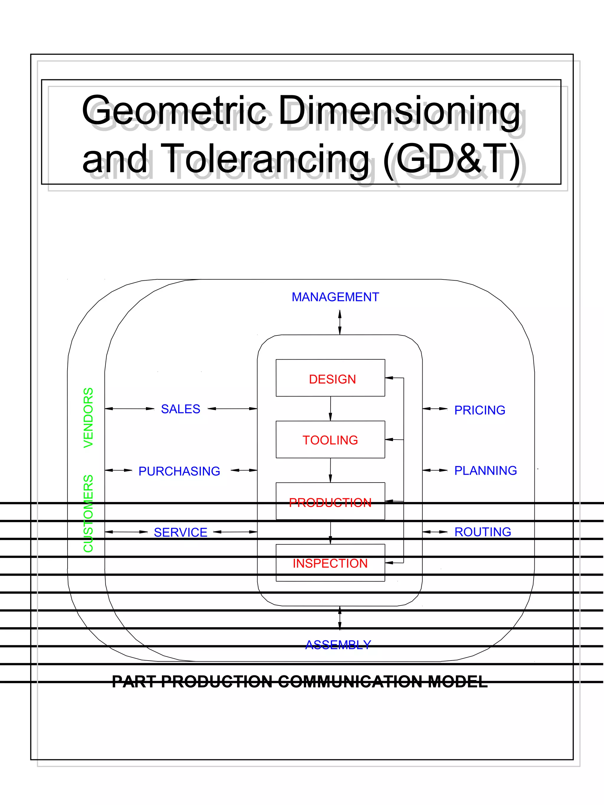
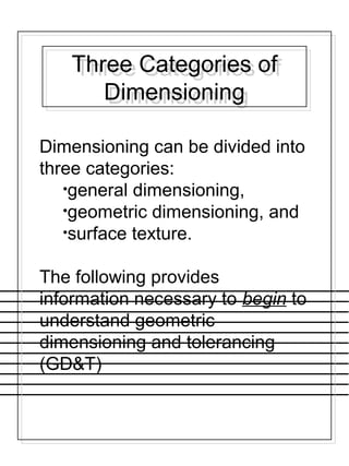
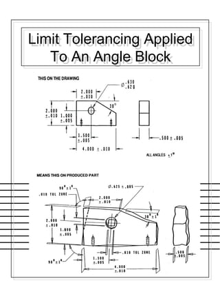
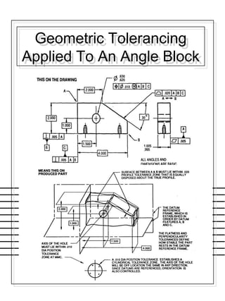
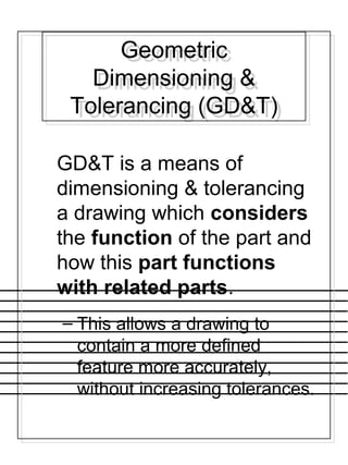
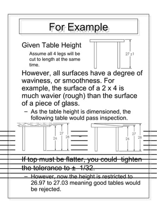
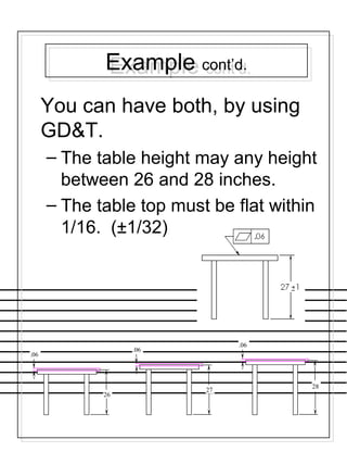
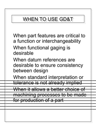
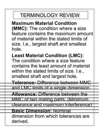
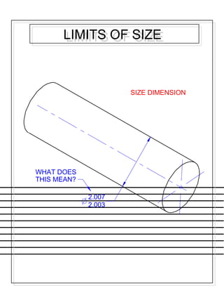
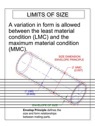
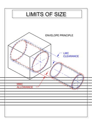
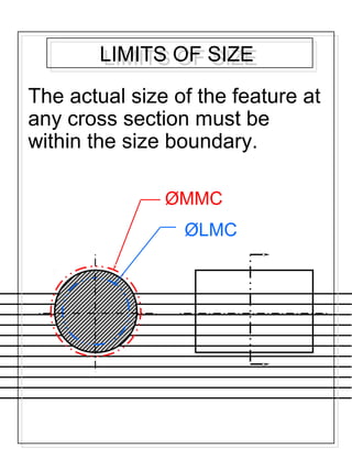
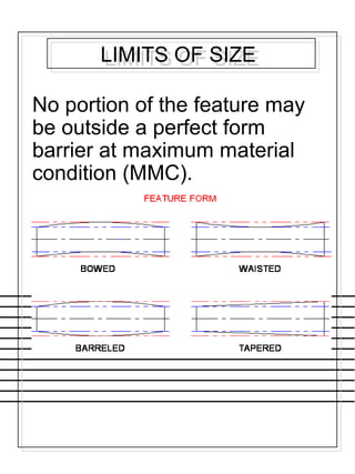
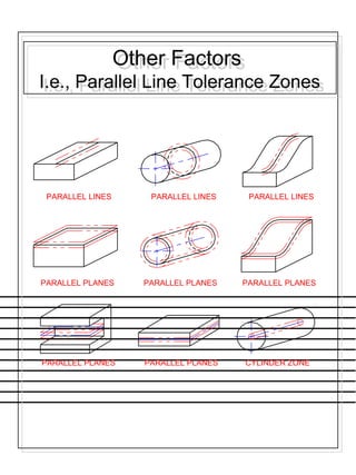
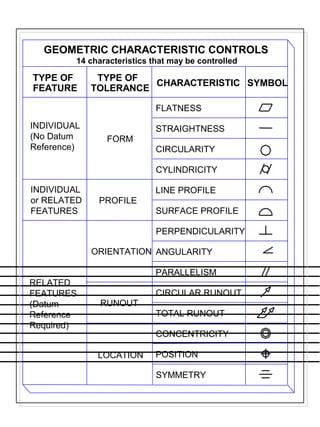
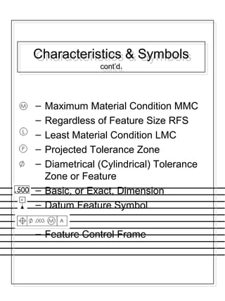
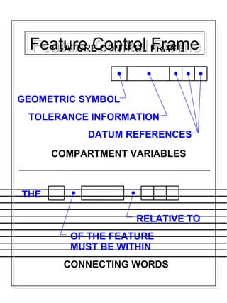
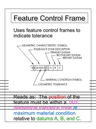
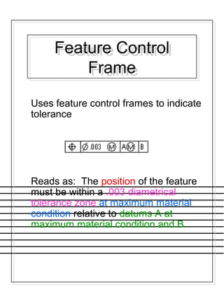
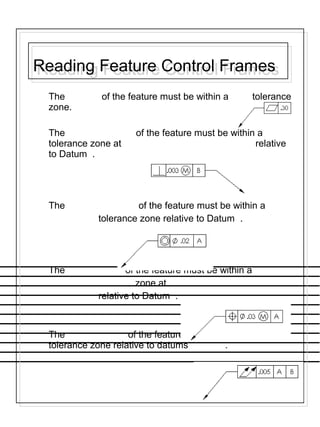
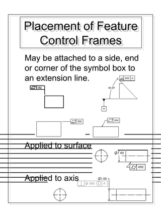
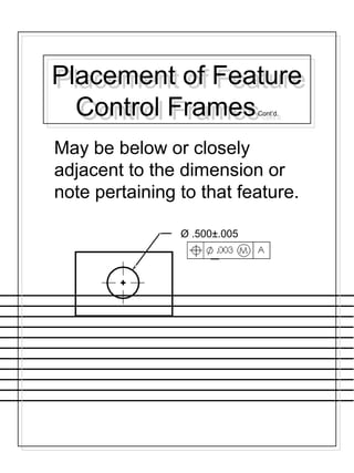
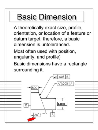
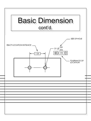
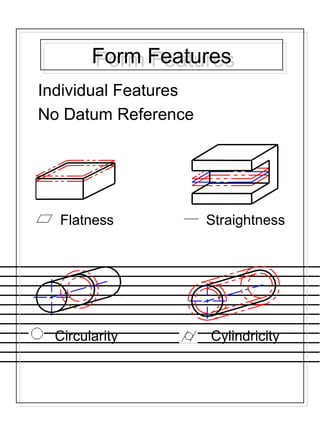
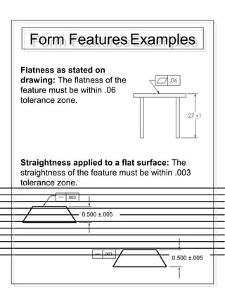
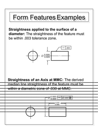
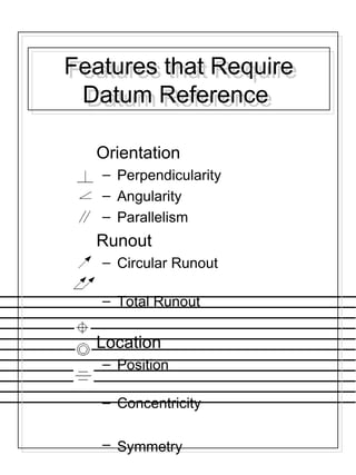
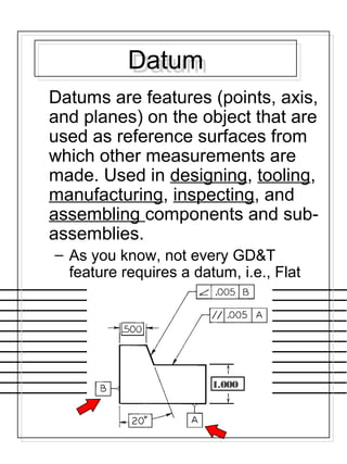
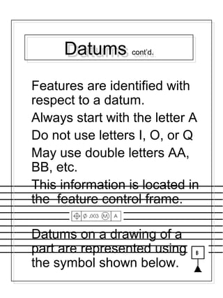
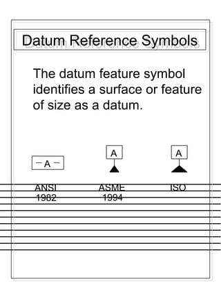
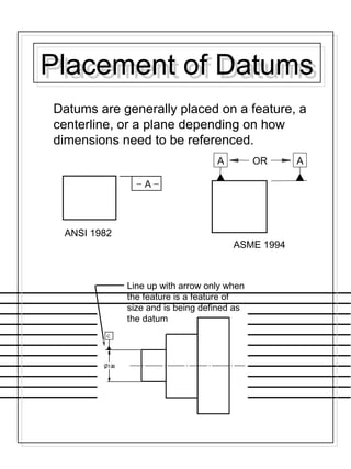
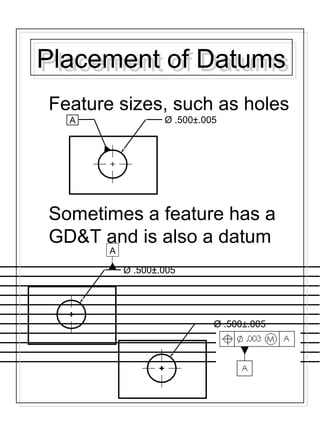
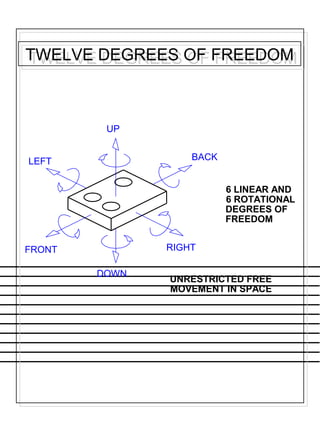
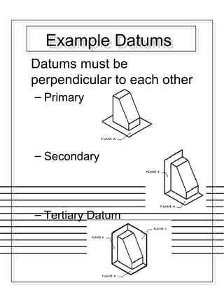
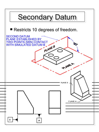
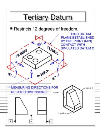
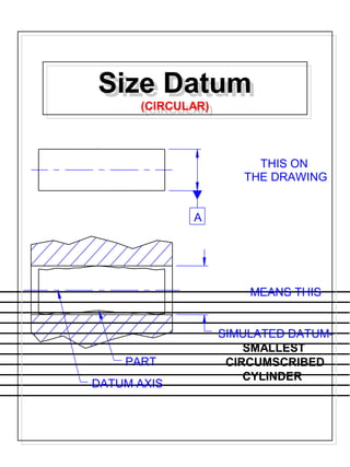
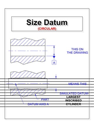
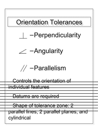
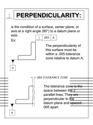
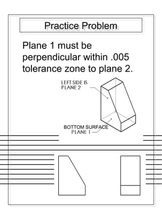
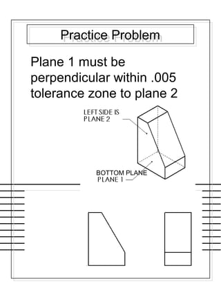
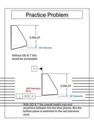
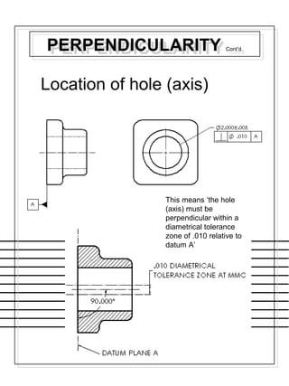
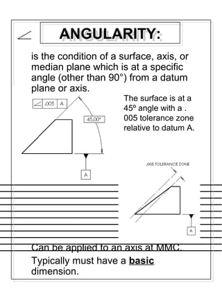
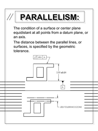
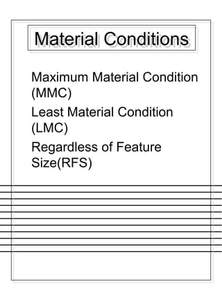
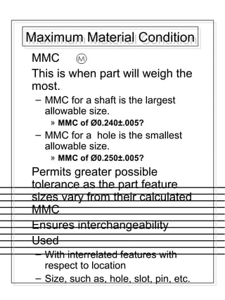
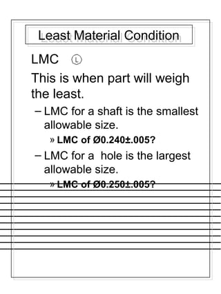
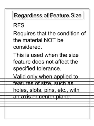
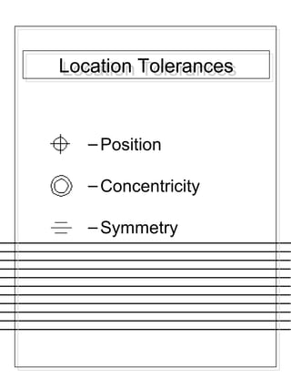
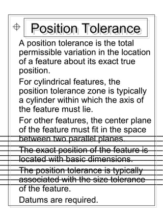
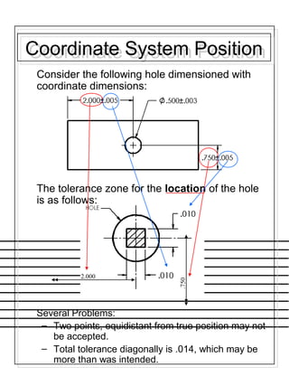
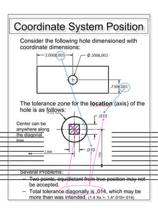
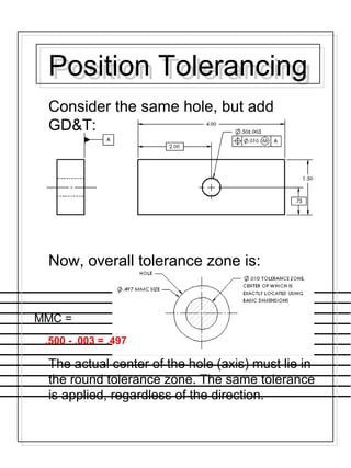
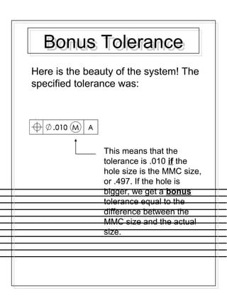
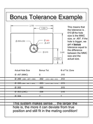
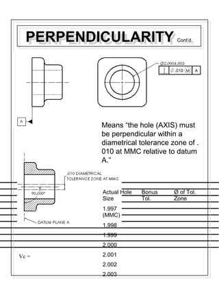

This document provides information on geometric dimensioning and tolerancing (GD&T). It discusses the three categories of dimensioning, including general, geometric, and surface texture. GD&T considers the function of a part and how parts interact. GD&T uses standard symbols to indicate tolerances based on a feature's geometry. GD&T aims to more precisely define features without increasing tolerances. Key aspects of GD&T covered include datums, maximum and least material conditions, tolerance zones, and feature control frames. Specific GD&T controls like perpendicularity, angularity, parallelism, and their symbols are explained. The importance of GD&T for functions like interchangeability is emphasized.