A basic 2 day training on understanding of GDnT,Geometrical Dimensioning & Tolerancing to Technical & Egineering Group as a common language in understanding Drawings.
Trainer & Speaker
Timothy Wooi,
20C,Taman Bahagia,06000,Jitra, Kedah. Malaysia
email: timothywooi2@gmail.com
Geometric dimensioning and tolerancing is the new way of describing the dimensions and tolerances. It developed by engineers and used by engineers in engineering drawings or drafting. It plays a very important role in engineering design.
This presentation contains all the basic information about GD&T.
GD&T is a means of dimensioning & tolerancing a drawing which considers the function of the part and how this part functions with related parts.
GD&T has increased in practice in last 15 years because of ISO 9000.
ISO 9000 requires not only that something be required, but how it is to be controlled. For example, how round does a round feature have to be?
GD&T is a system that uses standard symbols to indicate tolerances that are based on the feature’s geometry.
Sometimes called feature based dimensioning & tolerancing or true position dimensioning & tolerancing
GD&T practices are specified in ANSI Y14.5M-1994.
There are many problems associated with tolerances that can be solved by the application of Monte Carlo Simulation techniques. Other common methods for evaluating statistical tolerances are Taylor series approximation, experimental design techniques attributed to G. Taguchi. The method described herein is a simplified expansion of Taguchi 3 level factorial experiment, which takes each component center, high and low level, together with other components at their 3 levels. (A full factorial design). The method is illustrated and it will serve as an Excel template for 2, 3, 4 and 5 components. To achieve the objective of error propagation, the examples provided herein are limited to statistically normally distributed independent random variables.
Synthesis of Tolerances for Spacecraft MechanismIJSRD
Tolerance have a great impact on the quality and cost of the mechanism. Proper tolerance design enables complex mechanical assemblies consisting of numerous parts to assemble and work together in a proper manner so that they fulfill their design objectives. In this paper the tolerance of a spacecraft mechanism is analyzed using worst case and root sum square method. The tolerance synthesis of the spacecraft mechanism is done by direct linearization method.
Presentation complied by Drug Regulations – a not for profit organization from publicly available material form FDA , EMA, EDQM . WHO and similar organizations.
Visit www.drugregulations.org for the latest in Pharmaceuticals
ABOUT THE TRAINING PROGRAM :-
Failure Mode and Effects Analysis or FMEA is a structured technique to analyze a process to determine shortcomings and opportunities for improvement. By assessing the severity of a potential failure, the likelihood that the failure will occur, and the chance of detecting the failure, dozens or even hundreds of potential issues can be prioritized for improvement.
DESIGNED FOR :-
Sr. Engineer, Engineer, Supervisor and Foreman engaged in maintenance, operation, Store, Supply chain, Quality, Safety and Engineering activities.
OBJECTIVE :-
Employees completing this training will be able to effectively participate on an FMEA team and can make immediate contributions to quality and productivity improvement efforts.
This topic provides an understanding on the purposes of materials testing and deformities in certain materials. It also explains on the definition and principle on mechanical properties of materials, destructive and non-destructive tests.
Effect Of Bonus And Shift Tolerances On Stack Up Analysis By Arash Vakily
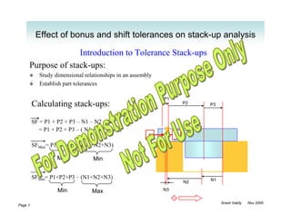
1. Effect of bonus and shift tolerances on stack-up analysis
Introduction to Tolerance Stack-ups
Purpose of stack-ups:
Study dimensional relationships in an assembly
Establish part tolerances
P1
Calculating stack-ups: P2 P3
SF = P1 + P2 + P3 – N1 – N2 – N3
= P1 + P2 + P3 – ( N1 + N2 + N3 )
S F
SFMax= P1+P2+P3 – (N1+N2+N3)
Max Min
SFMin= P1+P2+P3 – (N1+N2+N3) N1
N2
Min Max N3
Arash Vakily Nov 2005
Page 1
2. Effect of bonus and shift tolerances on stack-up analysis
Advantages of using a stack-up study form:
First step towards automation (using excel or other computer programs)
Organized, verifiable, easy to review (especially for bonus and shift calculations)
Arash Vakily Nov 2005
Page 2
3. Effect of bonus and shift tolerances on stack-up analysis
Stack-up Study Example Using the Form:
To find Min. distance between points S and F:
1
2 7
S F
5
6 4
3
X- 389
Arash Vakily Nov 2005
Page 3
4. Effect of bonus and shift tolerances on stack-up analysis
Virtual Condition
Virtual condition is used to evaluate mating and assembly of the parts
All types of GD&T affect virtual condition as shown in the above example
Arash Vakily Nov 2005
Page 4
5. Effect of bonus and shift tolerances on stack-up analysis
Example of Virtual Condition With Positional Tolerance
Note radial versus diametrical values when calculating tolerance stack-ups
/ 10 ± 0.2
VC = 10 + 0.2 + 0.3 VC
+ / 0.3 A
= 10.5
MM
C
R 0.15
VCRad = 5 + 0.1 + 0.15
Nominal
= 5.25
C
LM
0.1 0.1
0.15
Arash Vakily Nov 2005
Page 5
6. Effect of bonus and shift tolerances on stack-up analysis
Bonus Tolerance
/ 10 ± 0.2
.)
ad
+ / 0.3 M A
(R
s
nu
VC
Bo
At Bonus Value
MMC
MMC No Bonus 0
LMC MMC – LMC = 0.4
Total size tolerance
Any MMC - D 0 < B < 0.4
Diameter
D
Radial values are half of the values in the
above table +
Arash Vakily Nov 2005
Page 6
7. Effect of bonus and shift tolerances on stack-up analysis
Shift Tolerance
MMC = 5 + 0.4 = 5.4 / 10 ± 0.2
+ / 0.3 M
M
LMC = 5 – 0.4 = 4.6 A M
M
C
VC = 5.4 + 0.5 = 5.9
or
LM
C
At Shift Value
MMC MMC – VC 0.5
(Min Shift)
VC
Sh
LMC LMC – VC 1.3
ift
(R
(Max Shift)
ad
.)
Shift for the feature is calculated from
values of the Datum / 5 ± 0.4
Absolute values are used (no sign) + / 0.5 M B C D
A
Radial values are half of the values in the
above table Arash Vakily Nov 2005
Page 7
8. Effect of bonus and shift tolerances on stack-up analysis
Example of Bonus and Shift Tolerances
Max. Bonus = 8.6 – 8.3 = 0.3
Max. Radial Bonus = 0.3 / 2 = 0.15
Max. Shift = 12.6 – 12.4 = 0.2
Max. Radial Shift = 0.2 / 2 = 0.1
For calculations using stack-up study form, always Radial bonus and shift are used
Arash Vakily Nov 2005
Page 8
9. Effect of bonus and shift tolerances on stack-up analysis
How To Calculate Bonus and Shift Using Stack-up Study Form
Arash Vakily Nov 2005
Page 9
10. Effect of bonus and shift tolerances on stack-up analysis
Stack-up Study Example With Bonus and Shift:
To find Min. distance between points S and F:
2
2b 1
7
2s
S F
5
6 6b 6s 4
3
X- 389
Page Arash Vakily Nov 2005
10
11. Effect of bonus and shift tolerances on stack-up analysis
Examples of Special Considerations for Shift Tolerance
Radial Shift 1
2
Max.: 0.25
Min.: 0
3
Radial Shift
Max.: (LMC-VC) / 2 = 0.4
4 Min.: (MMC-VC) / 2 = 0.15
1. Shift (and bonus) calculations are valid for non-circular features that are symmetrical, such as slots and
grooves
2. When there is no MMC for the datum(s) used in stack-up, shift is zero. In this example, datums are planar.
For round datums that are regardless of feature size, same applies.
3. For features that are gauged simultaneously, such as two holes from the same pattern, shift is zero.
4. Example of shift tolerance where datum D itself has a positional tolerance.
Arash Vakily Nov 2005
Page 11